Table of Contents
Advertisement
Quick Links
OPERATION MANUAL
MODEL T802
PARAMAGNETIC OXYGEN ANALYZER
© TELEDYNE ADVANCED POLLUTION INSTRUMENTATION
9480 CARROLL PARK DRIVE
SAN DIEGO, CA 92121-5201
USA
Toll-free Phone: 800-324-5190
Phone: 858-657-9800
Fax: 858-657-9816
Email: api-sales@teledyne.com
Website: http://www.teledyne-api.com/
Copyright 2011
07275A DCN6005
Teledyne Advanced Pollution Instrumentation
18 February 2011
Advertisement
Table of Contents
Troubleshooting

Subscribe to Our Youtube Channel
Related Manuals for Teledyne T802


Summary of Contents for Teledyne T802
- Page 1 OPERATION MANUAL MODEL T802 PARAMAGNETIC OXYGEN ANALYZER © TELEDYNE ADVANCED POLLUTION INSTRUMENTATION 9480 CARROLL PARK DRIVE SAN DIEGO, CA 92121-5201 Toll-free Phone: 800-324-5190 Phone: 858-657-9800 Fax: 858-657-9816 Email: api-sales@teledyne.com Website: http://www.teledyne-api.com/ Copyright 2011 07275A DCN6005 Teledyne Advanced Pollution Instrumentation 18 February 2011...
-
Page 3: About Teledyne Advanced Pollution Instrumentation (Tapi
OLLUTION NSTRUMENTATION Teledyne Advanced Pollution Instrumentation, Inc. (TAPI) is a worldwide market leader in the design and manufacture of precision analytical instrumentation used for air quality monitoring, continuous emissions monitoring, and specialty process monitoring applications. Founded in San Diego, California,... - Page 4 Teledyne API T802 Paramagnetic O2 Analyzer Operation Manual This page intentionally left blank. 07275A DCN6005...
-
Page 5: Safety Messages
For Technical Assistance regarding the use and maintenance of this instrument or any other Teledyne API product, contact Teledyne API’s Customer Service Department: Telephone: 800-324-5190 Email: api-customerservice@teledyne.com or access any of the service options on our website at http://www.teledyne-api.com/ 07275A DCN6005... - Page 6 Teledyne API T802 Paramagnetic O2 Analyzer Operation Manual CONSIGNES DE SÉCURITÉ Des consignes de sécurité importantes sont fournies tout au long du présent manuel dans le but d’éviter des blessures corporelles ou d’endommager les instruments. Veuillez lire attentivement ces consignes.
-
Page 7: Warranty
AGREEMENT OF T-API'S PERFORMANCE HEREUNDER, WHETHER FOR BREACH OF WARRANTY OR OTHERWISE. Terms and Conditions All units or components returned to Teledyne API should be properly packed for handling and returned freight prepaid to the nearest designated Service Center. After the repair, the equipment will be returned, freight prepaid. - Page 8 Teledyne API T802 Paramagnetic O2 Analyzer Operation Manual This page intentionally left blank. 07275A DCN6005...
-
Page 9: About This Manual
SCH, LVDS TRANSMITTER BOARD 06731 SCH, AUXILLIARY-I/O BOARD NOTE Please read this manual in its entirety before making any attempt made to operate the instrument. REVISION HISTORY 2011 February 18 T802 Operation Manual, PN07275 Document Change Summary T802 Operation Manual 07275 6005... - Page 10 Teledyne API T802 Paramagnetic O2 Analyzer Operation Manual This page intentionally left blank. 07275A DCN6005...
-
Page 11: Table Of Contents
3.5.4. Functional Check........................... 37 3.6. Initial Calibration of the T802........................37 3.6.1. Interferents for O Paramagnetic Measurements.................. 37 3.6.2. Initial Calibration Procedure for T802 Analyzers without Options............37 3.6.3. CO Sensor Calibration Procedure ....................... 43 4. FREQUENTLY ASKED QUESTIONS.................45 4.1. FAQ’s................................45 4.2. - Page 12 6.5.1. SETUP CFG: Configuration Information................... 68 6.5.2. SETUP PASS: Password Feature ....................69 6.5.3. SETUP CLK: Setting the T802 Analyzer’s Internal Clock..............71 6.6. SETUP RNGE: Analog Output Reporting Range Configuration.............. 73 6.6.1. Physical Range versus Analog Output Reporting Ranges..............73 6.6.2.
- Page 13 9.1.2. Calibration Gases ..........................156 9.1.3. Data Recording Devices........................157 9.2. Manual Calibration Checks and Calibration of the T802 Analyzer in its Base Configuration..... 157 9.2.1. Setup for Basic Calibration Checks and Calibration ................158 9.2.2. Performing a Basic Manual Calibration Check..................159 9.2.3.
- Page 14 12.3.3. Performing Leak Checks ........................195 12.3.4. Performing a Sample Flow Check..................... 196 12.3.5. Cleaning the Optical Bench....................... 197 12.3.6. Cleaning Exterior Surfaces of the T802 .................... 197 13. TROUBLESHOOTING & REPAIR PROCEDURES ............198 13.1. General Troubleshooting .......................... 199 13.1.1. Fault Diagnosis with WARNING Messages ..................199 13.1.2.
- Page 15 Teledyne API T802 Paramagnetic O2 Analyzer Operation Manual Table of Contents LIST OF FIGURES Figure 3-1: Front Panel Layout ......................19 Figure 3-2. Display Screen and Touch Control................. 19 Figure 3-3.: Display/Touch Control Screen Mapped to Menu Charts..........21 Figure 3-4: Rear Panel Layout......................
- Page 16 Voltage Tolerances for the TEST CHANNEL Calibration ..........110 Table 7-9: Current Loop Output Check ..................114 Table 7-10: Test Channels Functions available on the T802’s Analog Output ....... 118 Table 7-11: Concentration Alarm Default Settings ..............122 Table 8-1: COM Port Communication Modes................
- Page 17 APPENDIX A - VERSION SPECIFIC SOFTWARE DOCUMENTATION A-1 - T802 Software Menu Trees, Software Version A.1 A-2 - T802 Setup Variables for Serial I/O, Software Version A.1 A-3 - T802 Warnings and Test Functions, Software Version A.1 A-4 - T802 Signal I/O Definitions, Software Version A.1 A-5 - T802 DAS Functions, Software Version A.1...
- Page 18 Table of Contents Teledyne API T802 Paramagnetic O2 Analyzer Operation Manual This page intentionally left blank. 07275A DCN6005...
- Page 19 SECTION I – GENERAL INFORMATION 07275A DCN6005...
- Page 20 Section 1 General Information Teledyne API T802 Paramagnetic O2 Analyzer Operation Manual This page intentionally left blank. 07275A DCN6005...
-
Page 21: Introduction
The Model T802 analyzer’s multi-tasking software gives the ability to track and report a large number of operational parameters in real time. These readings are compared to diagnostic limits kept in the analyzer’s memory where, should any fall outside of those limits, the analyzer issues automatic warnings. -
Page 22: Using This Manual
Also listed are Figures, Tables, and Appendices. SECTION I – GENERAL INFORMATION INTRODUCTION A brief description of the T802 analyzer architecture as well as a description of the layout of the manual and what information is located in its various sections. SPECIFICATIONS AND APPROVALS A list of the analyzer’s specifications, and if applicable, a description of the conditions and... - Page 23 Information and instructions for interacting with the T802 analyzer via its several remote interface options (e.g. via RS-232, its built-in digital control inputs/outputs, etc.) T802 VALIDATION AND VERIFICATION Methods and procedures for verifying the correct operation of your T802 Analyzer as well as step by step instructions for calibrating it. EPA PROTOCOL CALIBRATION Specific information regarding calibration requirements for analyzers used in EPA monitoring.
- Page 24 Introduction Teledyne API T802 Paramagnetic O2 Analyzer Operation Manual This page intentionally left blank. 07275A DCN6005...
-
Page 25: Specifications And Approvals
SPECIFICATIONS AND APPROVALS 2.1. SPECIFICATIONS Table 2-1: T802 Basic Unit Specifications PARAMETER SPECIFICATION Ranges 0-1% to 0-100.00% O by weight (User adjustable) Accuracy (intrinsic error) < ±0.1 % O Repeatability < ±0.01 % O Lower Detectable Limit < ±0.1 % O Zero Drift (24 hours) <... -
Page 26: Ce Mark Compliance
Specifications and Approvals Teledyne API T802 Paramagnetic O2 Analyzer Operation Manual 2.2. CE MARK COMPLIANCE 2.2.1. EMISSIONS COMPLIANCE The Teledyne API’s T802 O Analyzer was designed to be fully compliant with: EN61326 (1997 w/A1: 98 and A2: 01) Class A, EN61326-1 (2006) Class A device, FCC Part 15 Subpart B section 15.107 Class A, ICES-003 Class A (ANSI C63.4 1992) &... -
Page 27: Getting Started
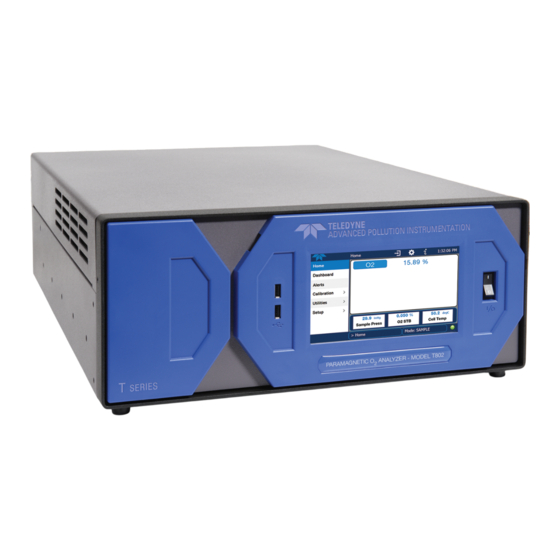
GETTING STARTED 3.1. T802 ANALYZER LAYOUT Figure 3-1: Front Panel Layout Figure 3-2. Display Screen and Touch Control 07275A DCN6005... -
Page 28: Table 3-1. Display Screen And Touch Control Description
Getting Started Teledyne API T802 Paramagnetic O2 Analyzer Operation Manual CAUTION – Avoid Damaging Touchscreen Do not use hard-surfaced instruments such as pens to operate the touchscreen. The front panel liquid crystal display screen includes touch control. Upon analyzer start-up, the screen shows a splash screen and other initialization indicators before the main display appears, similar to Figure 3-2 above (may or may not display a Fault alarm). -
Page 29: Figure 3-3.: Display/Touch Control Screen Mapped To Menu Charts
Teledyne API T802 Paramagnetic O2 Analyzer Operation Manual Getting Started Figure 3-3.: Display/Touch Control Screen Mapped to Menu Charts 07275A DCN6005... -
Page 30: Figure 3-4: Rear Panel Layout
Getting Started Teledyne API T802 Paramagnetic O2 Analyzer Operation Manual Figure 3-4: Rear Panel Layout 07275A DCN6005... -
Page 31: Table 3-2. Rear Panel Component Descriptions
Teledyne API T802 Paramagnetic O2 Analyzer Operation Manual Getting Started Table 3-2. Rear Panel Component Descriptions Component Function cooling fan Pulls ambient air into chassis through side vents and exhausts through rear. Connector for three-prong cord to apply AC power to the analyzer. -
Page 32: Figure 3-5: Internal Layout
Getting Started Teledyne API T802 Paramagnetic O2 Analyzer Operation Manual Figure 3-5: Internal Layout 07275A DCN6005... -
Page 33: Unpacking The T802 Analyzer
Teledyne API T802 Paramagnetic O2 Analyzer Operation Manual Getting Started Figure 3-6: T802 Internal Gas Flow (Basic Configuration) 3.2. UNPACKING THE T802 ANALYZER CAUTION ENERAL AFETY AZARD To avoid personal injury, always use two persons to lift and carry the T802. 07275A DCN6005... - Page 34 Getting Started Teledyne API T802 Paramagnetic O2 Analyzer Operation Manual CAUTION – AVOID WARRANTY INVALIDATION Printed circuit assemblies (PCAs) are sensitive to electro-static discharges too small to be felt by the human nervous system. Damage resulting from failure to use ESD protection when working with electronic assemblies will void the instrument warranty.
-
Page 35: Ventilation Clearance
Teledyne API T802 Paramagnetic O2 Analyzer Operation Manual Getting Started 3.2.1. VENTILATION CLEARANCE Whether the analyzer is set up on a bench or installed into an instrument rack, be sure to leave sufficient ventilation clearance. Table 3-3: Ventilation Clearance AREA... -
Page 36: Analog Inputs (Option 64) Connections
ENERAL AFETY AZARD The T802 analyzer can be configured for both 100-130 V and 210-240 V at either 47 or 63 Hz. To avoid damage to your analyzer, make sure that the AC power voltage matches the voltage indicated on the Analyzer’s serial number label tag (See Figure 3-4) before plugging the T802 into line power. -
Page 37: Analog Output Connections
Getting Started 3.3.3. ANALOG OUTPUT CONNECTIONS The T802 is equipped with several analog output channels accessible through the ANALOG OUT connector on the rear panel of the instrument. The standard configuration for these outputs is VDC. An optional current loop output is available for each (Section 5.4). -
Page 38: Connecting The Status Outputs
Getting Started Teledyne API T802 Paramagnetic O2 Analyzer Operation Manual 3.3.4. CONNECTING THE STATUS OUTPUTS The status outputs report analyzer conditions via optically isolated NPN transistors, which sink up to 50 mA of DC current. These outputs can be used to interface with devices that accept logic-level digital inputs, such as programmable logic controllers (PLCs). -
Page 39: Connecting The Control Inputs
Teledyne API T802 Paramagnetic O2 Analyzer Operation Manual Getting Started 3.3.5. CONNECTING THE CONTROL INPUTS If you wish to use the analyzer to remotely activate the zero and span calibration modes, several digital control inputs are provided through a 10-pin connector labeled CONTROL IN on the analyzer’s rear panel. -
Page 40: Communication Connections
If your network does not support DHCP, see Section 8.5.2 for instructions on manually configuring the LAN connection. 3.3.7. CONNECTING TO A MULTIDROP NETWORK If your unit has the optional Teledyne API RS-232 multidrop card, see Section 8.2 for instructions on setting it up. 07275A DCN6005... -
Page 41: Pneumatic Connections
AFETY AZARD While O is itself not toxic, the sample gas measured by, and in some cases the calibration gases used with the T802 can contain other components that are hazardous (e.g. NO, NO , SO , CO, etc). Obtain a Material Safety Data Sheet (MSDS) for each such gas. Read and rigorously follow the safety guidelines described there. -
Page 42: Pneumatic Connections To T802 Basic Configuration
Teledyne API T802 Paramagnetic O2 Analyzer Operation Manual 3.4.1.3. Other Parametric Gases It should be noted that other gases also react to magnetic influences and will be detected by the T802’s paramagnetic sensor. Usually this influence is extremely minor and can be disregarded; however,... - Page 43 Teledyne API T802 Paramagnetic O2 Analyzer Operation Manual Getting Started 3.4.2.1. Sample Gas Source Attach a sample inlet line to the SAMPLE inlet port. The SAMPLE input line should not be more than two (2) meters long. Maximum pressure of any gas at the SAMPLE inlet should not exceed 1.5 in-Hg above ambient pressure and ideally should equal ambient atmospheric pressure.
-
Page 44: Initial Operation
3.5.2. WARM UP The T802 requires about 60 minutes warm-up time before reliable measurements can be taken. During that time, various portions of the instrument’s front panel will behave as described in Table 3-10. Table 3-10: Front Panel Display during System Warm-Up... -
Page 45: Functional Check
Teledyne API T802 Paramagnetic O2 Analyzer Operation Manual Getting Started 3.5.4. FUNCTIONAL CHECK After the analyzer’s components have warmed up for at least 60 minutes, verify that the software properly supports any hardware options that were installed. For information on navigating through the analyzer’s software menus, see the menu trees described in Appendix A.1. - Page 46 Getting Started Teledyne API T802 Paramagnetic O2 Analyzer Operation Manual Cal gas will be supplied through the SAMPLE gas inlet on the back of the analyzer (see Figure 3-4), and; The pneumatic setup matches that described in Section 3.4.2.
- Page 47 Teledyne API T802 Paramagnetic O2 Analyzer Operation Manual Getting Started 3.6.2.1. Verifying the T802 Reporting Range Settings While it is possible to perform the following procedure with any range setting we recommend that you perform this initial checkout using the following reporting range settings: ...
- Page 48 Teledyne API T802 Paramagnetic O2 Analyzer Operation Manual 3.6.2.2. Dilution Ratio (Option) Set Up If the dilution ratio option is enabled on your T802 and your application involves diluting the sample gas before it enters the analyzer, set the dilution ratio as follows: SAMPLE RANGE=100.00 %...
- Page 49 Teledyne API T802 Paramagnetic O2 Analyzer Operation Manual Getting Started 3.6.2.3. Set O Span Gas Concentration Set the expected O span gas concentration. This should be 80% of concentration range for which the analyzer’s analog output range is set. SAMPLE RANGE=100.00 %...
- Page 50 Getting Started Teledyne API T802 Paramagnetic O2 Analyzer Operation Manual 3.6.2.4. Zero/Span Calibration To perform the zero/span calibration procedure, press: SAMPLE RANGE=100.00 % O2=XXX.XX Set the Display to show < TST TST > SETUP the STABIL test function. This function calculates...
-
Page 51: Co Sensor Calibration Procedure
Once you have completed the above set-up procedures, please fill out the Quality Questionnaire that was shipped with your unit and return it to Teledyne API. This information is vital to our efforts in continuously improving our service and our products. - Page 52 Getting Started Teledyne API T802 Paramagnetic O2 Analyzer Operation Manual This page intentionally left blank. 07275A DCN6005...
-
Page 53: Frequently Asked Questions
Q: Why is the ZERO or SPAN key not displayed during calibration? A: The T802 disables these keys when the expected span or zero value entered by the users is too different from the gas concentration actual measured value. This is to prevent the accidental recalibration of the analyzer to an out-of-range response curve. -
Page 54: Glossary
10 megabits per second (Mbps) 100BaseT same as 10BaseT except ten times faster (100 Mbps) APICOM name of a remote control program offered by Teledyne-API to its customers ASSY Assembly Code-Activated Switch Converter Efficiency, the percentage of light energy that is actually converted into... - Page 55 Teledyne API T802 Paramagnetic O2 Analyzer Operation Manual Frequently Asked Questions Term Description/Definition molecular oxygen ozone sulfur dioxide metric abbreviation for cubic centimeter (replaces the obsolete abbreviation “cc”) Central Processing Unit Digital-to-Analog Converter Data Acquisition System Data Communication Equipment DHCP Dynamic Host Configuration Protocol.
- Page 56 Frequently Asked Questions Teledyne API T802 Paramagnetic O2 Analyzer Operation Manual Term Description/Definition package used in electronic assemblies Internet Protocol Internal Zero Span Local Area Network Liquid Crystal Display Light Emitting Diode Liters Per Minute MOLAR MASS the mass, expressed in grams, of 1 mole of a specific substance. Conversely, one mole is the amount of the substance needed for the molar mass to be the same number in grams as the atomic mass of that substance.
- Page 57 Teledyne API T802 Paramagnetic O2 Analyzer Operation Manual Frequently Asked Questions Term Description/Definition Poly Vinyl Chloride, a polymer used for downstream tubing Reading RS-232 specification and standard describing a serial communication method between DTE (Data Terminal Equipment) and DCE (Data Circuit-terminating Equipment)
- Page 58 Frequently Asked Questions Teledyne API T802 Paramagnetic O2 Analyzer Operation Manual This page intentionally left blank. 07275A DCN6005...
-
Page 59: Optional Hardware And Software
5.3. CARRYING STRAP/HANDLE (OPT 29) The chassis of the T802 analyzer allows the user to attach a strap handle for carrying the instrument. The handle is located on the right side and pulls out to accommodate a hand for transport. When pushed in, the handle is nearly flush with the chassis, only protruding out about 9 mm (3/8”). -
Page 60: Current Loop Analog Outputs (Option 41)
Optional Hardware and Software Teledyne API T802 Paramagnetic O2 Analyzer Operation Manual Installing the strap handle prevents the use of the rack mount slides; however, the rack mount brackets, Option 21, can still be used. CAUTION ENERAL AFETY AZARD AVOID PERSONAL INJURY: We recommend two persons lift and carry the analyzer which weighs about 12.7 kg... -
Page 61: Converting Current Loop Analog Outputs To Standard Voltage Outputs
Teledyne API T802 Paramagnetic O2 Analyzer Operation Manual Optional Hardware and Software The Current Loop Option can be configured for any output range between 0 and 20mA DC. Most current loop applications require either 2-20 mA or 4-20 mA spans. Information on calibrating or adjusting these outputs can be found in 7.4.3.5. -
Page 62: Communication Options
5.6.2. CONCENTRATION ALARM RELAY (OPTION 61) The Teledyne API “E” series analyzers have an option for four (4) “dry contact” relays on the rear panel of the instrument. This relay option is different from and in addition to the “Contact Closures”... -
Page 63: Multidrop (Option 62)
Logic PCA that conditions the probe output and issues a 0-5 VDC signal to the analyzer’s CPU that is used to compute the CO concentration. The T802 receives this input, scales it based on the values of the CO2_SLOPE and CO2_OFFSET Recorded during calibration (see Section 9.5). The CO sensor assembly itself does not have any serviceable parts and is enclosed in an insulated canister. -
Page 64: Co Sensor Ranges And Specifications
Optional Hardware and Software Teledyne API T802 Paramagnetic O2 Analyzer Operation Manual 5.7.1. CO SENSOR RANGES AND SPECIFICATIONS The CO sensor in the T802 has a range of 0-20%. Table 5-2: CO Sensor Specifications Accuracy at 25˚C <±0.02%CO + 2% of reading Linearity 0.5 % of full scale... -
Page 65: Figure 5-4: T802 - Internal Pneumatics With Co
Teledyne API T802 Paramagnetic O2 Analyzer Operation Manual Optional Hardware and Software The sensor computes the ratio between the reference signal and the measurement signal to determine the degree of light absorbed by CO present in the sensor chamber. This dual wavelength method of... -
Page 66: Figure 5-5: Co 2 Sensor Option Pca Layout And Electronic Connections
Optional Hardware and Software Teledyne API T802 Paramagnetic O2 Analyzer Operation Manual 5.7.2.4. Electronic Operation of the CO Sensor The CO PCA is powered by 12 VDC from the analyzer via the relay card, which outputs a 0-5 VDC analog signal to the analyzer’s CPU via the motherboard that corresponds to the concentration of CO measured by the probe. - Page 67 SECTION II – OPERATING INSTRUCTIONS 07275A DCN6005...
- Page 68 Section II Operating Instructions Teledyne API T802 Paramagnetic O2 Analyzer Operation Manual This page intentionally left blank. 07275A DCN6005...
-
Page 69: Basic Operation
6.1. OVERVIEW OF OPERATING MODES The T802 software has a variety of operating modes. Most commonly, the analyzer will be operating in Sample Mode. In this mode a continuous read-out of the gas concentration is displayed on the front panel. -
Page 70: Table 6-1: Analyzer Operating Modes
This is the basic calibration mode of the instrument and is activated by pressing the CAL key. SETUP mode is being used to configure the analyzer. The gas measurement will continue during this SETUP [X.X process. The revision of the T802 firmware being run will appear after the word “SETUP” 2 & 3 CAL O2 Z[type] Unit is performing O ZERO calibration procedure. -
Page 71: Sample Mode
Teledyne API T802 Paramagnetic O2 Analyzer Operation Manual Basic Operation 6.2. SAMPLE MODE This is the analyzer’s standard operating mode. In this mode the instrument is analyzing the gas in the sample chamber, calculating O concentration and reporting this information to the user via the front panel display, the analog outputs and, if set up properly, the RS-232/485/Ethernet ports. -
Page 72: Table 6-2: Test Functions Defined
Basic Operation Teledyne API T802 Paramagnetic O2 Analyzer Operation Manual Table 6-2: Test Functions Defined PARAMETER DISPLAY TITLE UNITS MEANING RANGE The full scale limit at which the reporting range of the analyzer is currently set. THIS IS NOT the Physical Range of the instrument. -
Page 73: Warning Messages
Teledyne API T802 Paramagnetic O2 Analyzer Operation Manual Basic Operation 6.3. WARNING MESSAGES The most common instrument failures will be reported as a warning on the analyzer’s front panel and through the COM ports. Section 13.1.1 explains how to use these messages to troubleshoot problems. -
Page 74: Calibration Mode
6.4. CALIBRATION MODE The T802 will switch into calibration mode when the user presses the CAL key. In this mode the user can, in conjunction with introducing zero or span gases of known concentrations into the analyzer, cause it to adjust and recalculate the slope (gain) and offset of the its measurement range. -
Page 75: Setup Mode
Teledyne API T802 Paramagnetic O2 Analyzer Operation Manual Basic Operation 6.5. SETUP MODE The SETUP mode contains a variety of choices that are used to configure the analyzer’s hardware and software features, perform diagnostic procedures, gather information on the instrument’s performance and configure or access data from the internal data acquisition system (DAS). -
Page 76: Setup Cfg: Configuration Information
Special instrument or software features or installed options may also be listed here. Use this information to identify the software and hardware installed in your T802 analyzer when contacting customer service. To access the configuration table, press: SAMPLE RANGE=100.00 %... -
Page 77: Setup Pass: Password Feature
6.5.2. SETUP PASS: PASSWORD FEATURE When the T802’s SETUP mode is activated, the instrument will prompt the user to enter a security password. The default password is 818. This allows access to all of the instruments basic functions and operating modes as well as some of its more powerful diagnostic tools and variables. - Page 78 Basic Operation Teledyne API T802 Paramagnetic O2 Analyzer Operation Manual Example: If all passwords are enabled, the following keypad sequence would be required to enter the SETUP menu: SAMPLE RANGE=100.00 % O2=XXX.XX <TST TST> CAL SETUP SYSTEM ENTER SETUP PASS:0...
-
Page 79: Setup Clk: Setting The T802 Analyzer's Internal Clock
CLOCK 6.5.3.1. Setting the Internal Clock’s Time and Day The T802 has a time of day clock that supports the time of day TEST function, the time stamps for the DAS feature and most COM port messages. To set the clock’s time and day, press: (The ACAL submenu in the Primary Setup Menu is a special configuration;... - Page 80 Basic Operation Teledyne API T802 Paramagnetic O2 Analyzer Operation Manual The CLOCK_ADJUST variable is accessed via the VARS submenu: To change the value of this variable, press: (The ACAL submenu in the Primary Setup Menu is a special configuration; consult factory).
-
Page 81: Setup Rnge: Analog Output Reporting Range Configuration
21% of the range of the recording device. The T802 analyzers solve this problem by allowing the user to select a scaled reporting range for the analog outputs that only includes that portion of the physical range relevant to the specific application. - Page 82 Basic Operation Teledyne API T802 Paramagnetic O2 Analyzer Operation Manual All three outputs can be configured either at the factory or by the user for full scale outputs of 0.1 VDC, 1VDC, 5VDC or 10VDC. Additionally A1 and A2 may be equipped with optional 0-20 mA current loop drivers and configured for any current output within that range (e.g.
-
Page 83: Reporting Range Modes
Teledyne API T802 Paramagnetic O2 Analyzer Operation Manual Basic Operation 6.6.3. REPORTING RANGE MODES The T802 provides three analog output range modes to choose from. Single range (SNGL) mode sets a single maximum range for the analog output. If single range is selected both outputs are slaved together and will represent the same measurement span (e.g. - Page 84 Basic Operation Teledyne API T802 Paramagnetic O2 Analyzer Operation Manual 6.6.3.1. RNGE MODE SNGL: Configuring the T802 Analyzer for Single Range Mode NOTE This is the default reporting range mode for the analyzer. When the single range mode is selected (SNGL), all analog O concentration outputs (A1 and A2) are slaved together and set to the same reporting range limits (e.g.
- Page 85 Teledyne API T802 Paramagnetic O2 Analyzer Operation Manual Basic Operation 6.6.3.2. RNGE MODE DUAL: Configuring the T802 Analyzer for DUAL Range Mode Selecting the DUAL range mode allows the A1 and A2 outputs to be configured with different reporting ranges.
- Page 86 Basic Operation Teledyne API T802 Paramagnetic O2 Analyzer Operation Manual To set the upper range limit for each independent reporting range, press: (The ACAL submenu in the Primary Setup Menu is a special configuration; consult factory). 07275A DCN6005...
- Page 87 Teledyne API T802 Paramagnetic O2 Analyzer Operation Manual Basic Operation 6.6.3.3. RNGE MODE AUTO: Configuring the T802 Analyzer for AUTO Range Mode In AUTO range mode, the analyzer automatically switches the reporting range between two user-defined ranges (low and high).
-
Page 88: Setup Rnge Dil: Using The Optional Dilution Ratio Feature
Basic Operation Teledyne API T802 Paramagnetic O2 Analyzer Operation Manual 6.6.4. SETUP RNGE DIL: USING THE OPTIONAL DILUTION RATIO FEATURE This feature is a optional software utility that allows the user to compensate for any dilution of the sample gas that may occur before it enters the sample inlet. -
Page 89: Advanced Features
The DAS of the T802 can store up to about one million data points, which can, depending on individual configurations, cover days, weeks or months of valuable measurements. The data are stored in non- volatile memory and are retained even when the instrument is powered off. -
Page 90: Das Status
Advanced Features Teledyne API T802 Paramagnetic O2 Analyzer Operation Manual 7.1.1. DAS STATUS The green SAMPLE LED on the instrument front panel, which indicates the analyzer status, also indicates certain aspects of the DAS status: Table 7-1: Front Panel LED Status Indicators for DAS... -
Page 91: Default Das Channels
More with APICOM, but only the first six are displayed on the front panel). For information regarding the maximum number of channels, parameters, and records and how to calculate the file size for each data channel, refer to the DAS manual downloadable from the T-API website at http://www.teledyne-api.com/manuals/ under Special Manuals. - Page 92 Advanced Features Teledyne API T802 Paramagnetic O2 Analyzer Operation Manual DETAIL: Samples six different parameters related to the operating status of the analyzer’s optical sensors. For each parameter: A value is logged once every minute; An average of the last 60 readings is calculated once every minute (60 seconds).
-
Page 93: Figure 7-1: Default Das Channel Setup
Teledyne API T802 Paramagnetic O2 Analyzer Operation Manual Advanced Features Triggering Events and Data Parameters/Functions for these default channels are: Figure 7-1: Default DAS Channel Setup 07275A DCN6005... -
Page 94: Setup Das View: Viewing Das Channels And Individual Records
Advanced Features Teledyne API T802 Paramagnetic O2 Analyzer Operation Manual 7.1.4. SETUP DAS VIEW: VIEWING DAS CHANNELS AND INDIVIDUAL RECORDS DAS data and settings can be viewed on the front panel through the following keystroke sequence. SAMPLE SAMPLE RANGE=100.00 % RANGE=500.0 PPB... -
Page 95: Setup Das Edit: Accessing The Das Edit Mode
Teledyne API T802 Paramagnetic O2 Analyzer Operation Manual Advanced Features 7.1.5. SETUP DAS EDIT: ACCESSING THE DAS EDIT MODE DAS configuration is most conveniently done through the APICOM remote control program. The following list of key strokes shows how to edit using the front panel. - Page 96 Advanced Features Teledyne API T802 Paramagnetic O2 Analyzer Operation Manual 7.1.5.1. Editing DAS Data Channel Names To edit the name of a DAS data channel, follow the instruction shown in Section 7.1.5 then press: Starting at the EDIT CHANNEL MENU SETUP X.X...
- Page 97 Teledyne API T802 Paramagnetic O2 Analyzer Operation Manual Advanced Features 7.1.5.2. Editing DAS Triggering Events Triggering events define when and how the DAS records a measurement of any given data channel. The most commonly used triggering events are: ATIMER: Sampling at regular intervals specified by an automatic timer. Most trending information is usually stored at such regular intervals, which can be instantaneous or averaged.
-
Page 98: Table 7-3: Das Data Parameter Functions
Appendix A-5. 7.1.5.3. Editing DAS Parameters Data parameters are types of data that may be measured and stored by the DAS. For each Teledyne API analyzer model, the list of available data parameters is different, fully defined and not customizable. - Page 99 Teledyne API T802 Paramagnetic O2 Analyzer Operation Manual Advanced Features To modify, add or delete a parameter, follow the instruction shown in Section 7.1.5 then press: 07275A DCN6005...
- Page 100 Advanced Features Teledyne API T802 Paramagnetic O2 Analyzer Operation Manual NOTE When the STOR NUM SAMPLE feature is turned on, the instrument will store the number of measurements used to compute the AVG, SDEV, MIN or MAX value but not the actual measurements themselves.
- Page 101 Teledyne API T802 Paramagnetic O2 Analyzer Operation Manual Advanced Features To define the REPORT PERIOD, follow the instruction shown in Section 7.1.5 then press: The SAMPLE PERIOD and REPORT PERIOD intervals are synchronized to the beginning and end of the appropriate interval of the instrument’s internal clock.
- Page 102 Advanced Features Teledyne API T802 Paramagnetic O2 Analyzer Operation Manual NOTE In AVG, SDEV, MIN or MAX sample modes (see Section 7.1.5.3), the settings for the Sample Period and the Report Period determine the number of data points used each time the parameter is calculated, stored and reported to the COM ports.
- Page 103 Teledyne API T802 Paramagnetic O2 Analyzer Operation Manual Advanced Features To set the NUMBER OF RECORDS, follow the instruction shown in Section 7.1.5 then press: 7.1.5.7. RS-232 Report Function The DAS can automatically report data to the communications ports, where they can be captured with a terminal emulation program or simply viewed by the user using the APICOM software.
- Page 104 Advanced Features Teledyne API T802 Paramagnetic O2 Analyzer Operation Manual To enable automatic COM port reporting, follow the instruction shown in Section 7.1.5 then press: Starting at the EDIT CHANNEL MENU SETUP X.X 0) CONC: ATIMER 2, 4032, RS232 PREV NEXT...
- Page 105 Teledyne API T802 Paramagnetic O2 Analyzer Operation Manual Advanced Features 7.1.5.8. Enabling / Disabling the HOLD OFF Feature The DAS HOLD OFF feature prevents data collection during calibration operations. To enable or disable the HOLD OFF, follow the instruction shown in Section 7.1.5 then press: Starting at the EDIT CHANNEL MENU SETUP X.X...
-
Page 106: Disabling/Enabling Data Channels
Advanced Features Teledyne API T802 Paramagnetic O2 Analyzer Operation Manual 7.1.5.10. The Starting Date Feature This option allows specifying a starting date for any given channel when the user wants to start data acquisition only after a certain time and date. If the STARTING DATE is in the past (the default condition), the DAS ignores this setting and begins recording data as defined by the REPORT PERIOD setting. -
Page 107: Remote Das Configuration
Back up data and the original DAS configuration before attempting any DAS changes. Refer to Section 8 for details on remote access to and from the T802 analyzer via the instrument’s COM ports. 07275A DCN6005... -
Page 108: Setup More Vars: Internal Variables (Vars)
VARS menu. The following table lists all variables that are available within the 818 password protected level. See Appendix A2 for a detailed listing of all of the T802 variables that are accessible through the remote interface. Table 7-4: Variable Names (VARS) - Page 109 Teledyne API T802 Paramagnetic O2 Analyzer Operation Manual Advanced Features To access and navigate the VARS menu, use the following key sequence. SAMPLE RANGE=100.00 % O2=XXX.XX <TST TST> CAL SETUP SETUP X.X PRIMARY SETUP MENU CFG ACAL DAS RNGE PASS CLK...
-
Page 110: Setup More Diag: Using The Diagnostics Functions
Advanced Features Teledyne API T802 Paramagnetic O2 Analyzer Operation Manual 7.3. SETUP MORE DIAG: USING THE DIAGNOSTICS FUNCTIONS A series of diagnostic tools is grouped together under the SETUPMOREDIAG menu. These tools can be used in a variety of troubleshooting and diagnostic procedures and are referred to in many places of the maintenance and trouble-shooting sections of this manual. -
Page 111: Accessing The Diagnostic Features
Teledyne API T802 Paramagnetic O2 Analyzer Operation Manual Advanced Features 7.3.1. ACCESSING THE DIAGNOSTIC FEATURES To access the DIAG functions press the following keys: SAMPLE RANGE=100.00 % O2=XXX.XX <TST TST> CAL SETUP SETUP X.X PRIMARY SETUP MENU CFG DAS ACAL RNGE PASS CLK... -
Page 112: Using The T802 Analyzer's Analog Outputs
The fourth output (A4) outputs a signal that can be set to represent the current value of one of several test functions (see Table 7-10). 7.4.1. ACCESSING THE ANALOG OUTPUT SIGNAL CONFIGURATION SUBMENU The following lists the analog I/O functions that are available in the T802 analyzer. Table 7-6: DIAG - Analog I/O Functions SUB MENU FUNCTION Initiates a calibration of the A1, A2, A3 and A4 analog output channels that determines the slope and offset inherent in the circuitry of each output. - Page 113 Teledyne API T802 Paramagnetic O2 Analyzer Operation Manual Advanced Features To access the ANALOG I/O CONFIGURATION sub menu, press: SAMPLE RANGE=100.00 % O2=XXX.XX <TST TST> CAL SETUP SETUP X.X PRIMARY SETUP MENU CFG ACAL DAS RNGE PASS CLK MORE EXIT SETUP X.X...
-
Page 114: Analog Output Voltage / Current Range Selection
Advanced Features Teledyne API T802 Paramagnetic O2 Analyzer Operation Manual 7.4.2. ANALOG OUTPUT VOLTAGE / CURRENT RANGE SELECTION In its standard configuration the analog outputs are set to output a 0 – 5 VDC signals. Several other output ranges are available. Each range is usable from -5% to + 5% of the rated span. -
Page 115: Calibration Of The Analog Outputs
Teledyne API T802 Paramagnetic O2 Analyzer Operation Manual Advanced Features 7.4.3. CALIBRATION OF THE ANALOG OUTPUTS Analog output calibration should to be carried out on first startup of the analyzer (performed in the factory as part of the configuration process) or whenever recalibration is required. The analog outputs can be calibrated automatically, either as a group or individually, or adjusted manually. - Page 116 Advanced Features Teledyne API T802 Paramagnetic O2 Analyzer Operation Manual 7.4.3.2. Automatic Group Calibration of the Analog Outputs NOTE Before performing this procedure, make sure that the AUTO CAL for each analog output is enabled. (See Section 7.4.3.1) To calibrate the outputs as a group with the AOUTS CALIBRATION command, select the ANALOG I/O CONFIGURATION submenu (see Section 7.4.1) then press:...
- Page 117 Teledyne API T802 Paramagnetic O2 Analyzer Operation Manual Advanced Features 07275A DCN6005...
-
Page 118: Figure 7-3: Setup For Checking / Calibrating Dcv Analog Output Signal Levels
Advanced Features Teledyne API T802 Paramagnetic O2 Analyzer Operation Manual 7.4.3.4. Manual Calibration of the Analog Outputs Configured for Voltage Ranges For highest accuracy, the voltages of the analog outputs can be manually calibrated. NOTE: The menu for manually adjusting the analog output signal level will only appear if the AUTO-CAL feature is turned off for the channel being adjusted (See Section 7.4.3.1). - Page 119 Teledyne API T802 Paramagnetic O2 Analyzer Operation Manual Advanced Features To adjust the signal levels of an analog output channel manually, select the ANALOG I/O CONFIGURATION submenu (see Section 7.4.1) then press: 07275A DCN6005...
-
Page 120: Figure 7-4: Setup For Checking / Calibration Current Output Signal Levels Using An Ammeter
Advanced Features Teledyne API T802 Paramagnetic O2 Analyzer Operation Manual 7.4.3.5. Manual Adjustment of Current Loop Option Output Span and Offset A current loop option may be purchased for the A1, A2 and A3 analog outputs of the analyzer. This option places circuitry in series with the output of the A-to-D converter on the motherboard that changes the normal DC voltage output to a 0-20 milliamp signal (See Section 5.4). - Page 121 Teledyne API T802 Paramagnetic O2 Analyzer Operation Manual Advanced Features To adjust the zero and span signal levels of the current outputs, select the ANALOG I/O CONFIGURATION submenu (see Section 7.4.1) then press: 07275A DCN6005...
-
Page 122: Figure 7-5: Alternative Setup Using 250Ω Resistor For Checking Current Output Signal Levels
Advanced Features Teledyne API T802 Paramagnetic O2 Analyzer Operation Manual An alternative method for measuring the output of the Current Loop converter is to connect a 250 ohm 1% resistor across the current loop output in lieu of the current meter (see Figure 3-8 for pin assignments and diagram of the analog output connector). -
Page 123: Turning An Analog Output Over-Range Feature On/Off
7.4.4. TURNING AN ANALOG OUTPUT OVER-RANGE FEATURE ON/OFF In its default configuration, a ± 5% over-range is available on each of the T802’s analog outputs. This over-range can be disabled if your recording device is sensitive to excess voltage or current. - Page 124 Advanced Features Teledyne API T802 Paramagnetic O2 Analyzer Operation Manual 07275A DCN6005...
-
Page 125: Adding A Recorder Offset To An Analog Output
This can be achieved in the T802 by defining a zero offset, a small voltage (e.g., 10% of span). To add a zero offset to a specific analog output channel, select the ANALOG I/O CONFIGURATION submenu (see Section 7.4.1) then press:... -
Page 126: Selecting A Test Channel Function For Output A4
Teledyne API T802 Paramagnetic O2 Analyzer Operation Manual 7.4.6. SELECTING A TEST CHANNEL FUNCTION FOR OUTPUT A4 The test functions available to be reported are: Table 7-10: Test Channels Functions available on the T802’s Analog Output TEST CHANNEL DESCRIPTION ZERO... - Page 127 Teledyne API T802 Paramagnetic O2 Analyzer Operation Manual Advanced Features To activate the TEST Channel and select a function (in this example SAMPLE PRESSURE), press: SAMPLE RANGE=100.00 % O2=XXX.XX <TST TST> CAL SETUP SETUP X.X PRIMARY SETUP MENU CFG ACAL DAS...
-
Page 128: Ain Calibration
Teledyne API T802 Paramagnetic O2 Analyzer Operation Manual 7.4.7. AIN CALIBRATION This is the sub-menu to conduct a calibration of the T802 analyzer’s analog inputs. This calibration should only be necessary after major repair such as a replacement of CPU, motherboard or power supplies. -
Page 129: Analog Inputs (Xin1
Teledyne API T802 Paramagnetic O2 Analyzer Operation Manual Advanced Features 7.4.8. ANALOG INPUTS (XIN1…XIN8) OPTION CONFIGURATION To configure the analyzer’s optional analog inputs, define for each channel: gain (number of units represented by 1 volt) offset (volts) ... -
Page 130: Setup More Alrm: Using The Gas Concentration Alarms (Option 61)
Advanced Features Teledyne API T802 Paramagnetic O2 Analyzer Operation Manual 7.5. SETUP MORE ALRM: USING THE GAS CONCENTRATION ALARMS (OPTION 61) The T802 includes two O concentration alarms. Each alarm has a user settable limit, and is associated with an opto-isolated TTL relay accessible via the status output connector on the instrument’s back panel (See Section 3.3.4). -
Page 131: Remote Operation
8.1. SETUP MORE COM: USING THE ANALYZER’S COMMUNICATION PORTS The T802 is equipped with an Ethernet port, a USB port and two serial communication (COM) ports (RS232 and COM2) located on the rear panel (see Figure 3-2). Both COM ports operate similarly and give the user the ability to communicate with, issue commands to, and receive data from the analyzer through an external computer system or terminal. -
Page 132: Com Port Baud Rate
Remote Operation Teledyne API T802 Paramagnetic O2 Analyzer Operation Manual Data Bits: 8 data bits with 1 stop bit. Parity: None. 8.1.3. COM PORT BAUD RATE To select the baud rate of either one of the COM Ports, press:... -
Page 133: Com Port Communication Modes
Modes are listed in the order in which they appear in the SETUP MORE COM COM[1 OR 2] MODE menu The default setting for this feature is ON. Do not disable unless instructed to by Teledyne API Customer Service personnel. - Page 134 Remote Operation Teledyne API T802 Paramagnetic O2 Analyzer Operation Manual Press the following keys to select communication modes for one of the COM Ports, such as the following example where RS-485 mode is enabled: (The ACAL submenu in the Primary Setup Menu is a special configuration; consult factory).
-
Page 135: Com Port Testing
Teledyne API T802 Paramagnetic O2 Analyzer Operation Manual Remote Operation 8.1.5. COM PORT TESTING The serial ports can be tested for correct connection and output in the COM menu. This test sends a string of 256 ‘w’ characters to the selected COM port. While the test is running, the red LED on the rear panel of the analyzer should flicker. -
Page 136: Machine Id
Teledyne API T802 Paramagnetic O2 Analyzer Operation Manual 8.1.6. MACHINE ID Each type of Teledyne API’s analyzer is configured with a default ID code. The default ID code for the T802 analyzers is 802. The ID number is only important if more than one analyzer is connected to the same communications channel such as when several analyzers are: ... -
Page 137: Terminal Operating Modes
Remote Operation 8.1.7. TERMINAL OPERATING MODES The T802 can be remotely configured, calibrated or queried for stored data through the serial ports. As terminals and computers use different communication schemes, the analyzer supports two communication modes specifically designed to interface with these two types of devices. -
Page 138: Table 8-3: Teledyne Api Serial I/O Command Types
Remote Operation Teledyne API T802 Paramagnetic O2 Analyzer Operation Manual 8.1.7.2. Command Syntax Commands are not case-sensitive and all arguments within one command (i.e. ID numbers, keywords, data values, etc.) must be separated with a space character. All Commands follow the syntax: X [ID] COMMAND <CR>... - Page 139 8.1.7.5. COM Port Password Security In order to provide security for remote access of the T802, a LOGON feature can be enabled to require a password before the instrument will accept commands. This is done by turning on the SECURITY MODE (Mode 4, Section 8.1.4).
-
Page 140: Remote Access By Modem
8.1.8. REMOTE ACCESS BY MODEM The T802 can be connected to a modem for remote access. This requires a cable between the analyzer’s COM port and the modem, typically a DB-9F to DB-25M cable (available from Teledyne API with PN WR0000024). - Page 141 Teledyne API T802 Paramagnetic O2 Analyzer Operation Manual Remote Operation To change this setting press: (The ACAL submenu in the Primary Setup Menu is a special configuration; consult factory). 07275A (DCN6005) 07275A DCN6005...
- Page 142 Remote Operation Teledyne API T802 Paramagnetic O2 Analyzer Operation Manual To initialize the modem press: SAMPLE RANGE=100.00 % O2=XXX.XX <TST TST> CAL SETUP SETUP X.X PRIMARY SETUP MENU CFG ACAL DAS RNGE PASS CLK MORE EXIT SETUP X.X SECONDARY SETUP MENU...
-
Page 143: Multidrop Rs-232 Set Up
Teledyne API T802 Paramagnetic O2 Analyzer Operation Manual Remote Operation 8.2. MULTIDROP RS-232 SET UP When the RS-232 Multidrop option is installed, the instrument designated as last in the chain must be terminated. This requires installing a shunt between two pins on the multidrop printed circuit assembly (PCA) inside the instrument. -
Page 144: Configuration Of Com2
4-digit identification number, press the button of the digit to be changed). Note Teledyne API recommends setting up the first link between the Host and the first analyzer and testing it before setting up the rest of the chain. -
Page 145: Modbus Setup
The following set of instructions assumes that the user is familiar with MODBUS communications, and provides minimal information to get started. For additional instruction, please refer to the Teledyne API MODBUS manual, PN 06276. Also refer to www.modbus.org for MODBUS communication protocols. - Page 146 Remote Operation Teledyne API T802 Paramagnetic O2 Analyzer Operation Manual Example Read/Write Definition window: Example Connection Setup window: Example MODBUS Poll window: 07275A (DCN6005) 07275A DCN6005...
-
Page 147: Remote Access Via The Ethernet
IP address. 8.5.1. CONFIGURING THE ETHERNET INTERFACE USING DHCP The Ethernet for your T802 uses Dynamic Host Configuration Protocol (DHCP) to configure its interface with your LAN automatically. This requires that your network servers also be running DHCP. The analyzer will do this the first time you turn the instrument on after it has been physically connected to your network. -
Page 148: Table 8-5: Lan/Internet Configuration Properties
HOST NAME addressed from other computers on the LAN or via the Internet. To change, see Section 8.5.3. Do not change the setting for this property unless instructed to by Teledyne API’s Customer Service personnel. NOTE If the gateway IP, instrument IP and the subnet mask are all zeroes (e.g. “0.0.0.0”), the DCHP was not successful in which case you may have to configure the analyzer’s Ethernet properties... - Page 149 Teledyne API T802 Paramagnetic O2 Analyzer Operation Manual Remote Operation To view the above properties listed in Table 8-5, press: (The ACAL submenu in the Primary Setup Menu is a special configuration; consult factory). 07275A (DCN6005) 07275A DCN6005...
-
Page 150: Manually Configuring The Network Ip Addresses
Remote Operation Teledyne API T802 Paramagnetic O2 Analyzer Operation Manual 8.5.2. MANUALLY CONFIGURING THE NETWORK IP ADDRESSES There are several circumstances when you may need to configure the interface settings of the analyzer’s Ethernet card manually: your LAN is not running a DHCP software package ... - Page 151 Teledyne API T802 Paramagnetic O2 Analyzer Operation Manual Remote Operation Internet Configuration Touchscreen Functions (Continued from preceding illustration) BUTTON FUNCTION Press this key to cycle through the range of numerals and available characters (“0 – 9” & “ . ”) <CH CH>...
-
Page 152: Changing The Analyzer's Hostname
The HOSTNAME is the name by which the analyzer appears on your network. The default name for all Teledyne API T802 analyzers is T802. To change this name (particularly if you have more than one T802 analyzer on your network), press: BUTTON FUNCTION <CH... -
Page 153: Using The T802 With A Hessen Protocol Network
Teledyne API web site: http://www.teledyne-api.com/manuals/ 8.6.2. HESSEN COM PORT CONFIGURATION Hessen protocol requires the communication parameters of the T802’s COM ports to be set differently than the standard configuration as shown in the table below. Table 8-6: RS-232 Communication Parameters for Hessen Protocol... -
Page 154: Activating Hessen Protocol
Teledyne API T802 Paramagnetic O2 Analyzer Operation Manual 8.6.3. ACTIVATING HESSEN PROTOCOL Once the COM port has been properly configured, the next step in configuring the T802 to operate over a Hessen protocol network is to activate the Hessen mode for COM ports and configure the communication parameters for the port(s) appropriately. -
Page 155: Selecting A Hessen Protocol Type
For more specific information about the difference between TYPE 1and TYPE 2 download the Manual Addendum for Hessen Protocol from the Teledyne API web site: http://www.teledyne-api.com/manuals/. To select a Hessen Protocol Type press:... -
Page 156: Setting The Hessen Protocol Response Mode
Teledyne API T802 Paramagnetic O2 Analyzer Operation Manual 8.6.5. SETTING THE HESSEN PROTOCOL RESPONSE MODE The Teledyne API implementation of Hessen Protocol allows the user to choose one of several different modes of response for the analyzer. Table 8-7: Teledyne API Hessen Protocol Response Modes... -
Page 157: Hessen Protocol Gas List Entries
Remote Operation 8.6.6. HESSEN PROTOCOL GAS LIST ENTRIES 8.6.6.1. Gas List Entry Format and Definitions The T802 analyzer keeps a list of available gas types. Each entry in this list is of the following format. [GAS TYPE],[RANGE],[GAS ID],[REPORTED] WHERE: GAS TYPE = The type of gas being reported (e.g. - Page 158 Remote Operation Teledyne API T802 Paramagnetic O2 Analyzer Operation Manual 8.6.6.2. Editing or Adding Hessen Gas List Entries To add or edit an entry to the Hessen Gas List, press: (The ACAL submenu in the Primary Setup Menu is a special configuration; consult factory).
- Page 159 Teledyne API T802 Paramagnetic O2 Analyzer Operation Manual Remote Operation 8.6.6.3. Deleting Hessen Gas List Entries To delete an entry from the Hessen Gas list, press: (The ACAL submenu in the Primary Setup Menu is a special configuration; consult factory).
-
Page 160: Setting Hessen Protocol Status Flags
Teledyne API T802 Paramagnetic O2 Analyzer Operation Manual 8.6.7. SETTING HESSEN PROTOCOL STATUS FLAGS Teledyne API’s implementation of Hessen protocols includes a set of status bits that the instrument includes in responses to inform the host computer of its condition. Each bit can be assigned to one operational and warning message flag. -
Page 161: Instrument Id Code
Each instrument on a Hessen Protocol network must have a unique ID code. If more than one T802 analyzer is on the Hessen network, you will have to change this code for all but one of the T802 analyzer’s on the Hessen network (see Section 8.1.6). -
Page 162: Apicom Remote Control Program
Teledyne API’s main line of ambient and stack-gas instruments from a remote connection through direct cable, modem or Ethernet. Running APICOM, a user can: Establish a link from a remote location to the T802 through direct cable connection via RS-232 ... -
Page 163: Calibration Procedures
CALIBRATION PROCEDURES This section contains a variety of information regarding the various methods for calibrating a T802 as well as other supporting information This section is organized as follows: SECTION 9.1 – BEFORE CALIBRATION This section contains general information you should know before calibrating the analyzer. -
Page 164: Before Calibration
If any problems occur while performing the following calibration procedures, refer to Section 13 for troubleshooting tips. 9.1.1. REQUIRED EQUIPMENT, SUPPLIES, AND EXPENDABLES Calibration of the T802 analyzer requires a certain amount of equipment and supplies. These include, but are not limited to, the following: ... -
Page 165: Data Recording Devices
For electronic data recording, the T802 provides an internal data acquisition system (DAS), which is described in detail in Section 7.1 APICOM, a remote control program, is also provided as a convenient and powerful tool for data handling, download, storage, quick check and plotting (see Section 8.7). -
Page 166: Setup For Basic Calibration Checks And Calibration
Calibration Procedures Teledyne API T802 Paramagnetic O2 Analyzer Operation Manual 9.2.1. SETUP FOR BASIC CALIBRATION CHECKS AND CALIBRATION Connect the Sources of Zero Air and Span Gas as shown below. Figure 9-1: Pneumatic Connections–Basic Configuration–Using Bottled Span Gas 07275A (DCN6005) -
Page 167: Performing A Basic Manual Calibration Check
See Section 13 for troubleshooting tips. 9.2.3. PERFORMING A BASIC MANUAL CALIBRATION The following section describes the basic method for manually calibrating the T802. If the analyzer’s reporting range is set for the DUAL or AUTO range modes, a step will appear for selecting which range is to be calibrated: RNG1 (LOW) or RNG2 (HIGH). - Page 168 Calibration Procedures Teledyne API T802 Paramagnetic O2 Analyzer Operation Manual 9.2.3.1. Setting the Expected Span Gas Concentration NOTE When setting expected concentration values, consider impurities in your span gas. The expected O span gas concentration should be 80% of the reporting range of the instrument (see Section 6.6.1)
- Page 169 Teledyne API T802 Paramagnetic O2 Analyzer Operation Manual Calibration Procedures 9.2.3.2. Zero/Span Point Calibration Procedure 07275A (DCN6005) 07275A DCN6005...
-
Page 170: O 2 Calibration Quality
OFFSET -0.500 0.000 0.500 These values should not be significantly different from the values recorded on the Teledyne API Final Test and Validation Data Sheet that was shipped with your instrument. Section 13 If they are, refer to troubleshooting in The default DAS configuration records all calibration values in channel CALDAT as well as all calibration check (zero and span) values in its internal memory. -
Page 171: Flow Calibration
Teledyne API T802 Paramagnetic O2 Analyzer Operation Manual Calibration Procedures The sample gas-line vent from the sample gas inlet on the instrument’s rear panel. To cause the analyzer to measure and record a value for PRES, press. (The ACAL submenu in the Primary Setup Menu is a special configuration; consult factory). - Page 172 Calibration Procedures Teledyne API T802 Paramagnetic O2 Analyzer Operation Manual SAMPLE RANGE=100.00 % O2=XXX.XX <TST TST> SETUP SETUP X.X PRIMARY SETUP MENU DAS ACAL RANG PASS CLK MORE EXIT SETUP X.X SECONDARY SETUP MENU COMM VARS DIAG EXIT SETUP X.X...
-
Page 173: Calibration Of The Optional Co Sensor
Teledyne API T802 Paramagnetic O2 Analyzer Operation Manual Calibration Procedures 9.5. CALIBRATION OF THE OPTIONAL CO SENSOR 9.5.1. CO CALIBRATION SETUP The pneumatic connections for calibrating are as follows Figure 9-2: Sensor Calibration Set Up SENSOR ZERO GAS: Teledyne API recommends using pure N... -
Page 174: Activate Co
Calibration Procedures Teledyne API T802 Paramagnetic O2 Analyzer Operation Manual 9.5.3. ACTIVATE CO SENSOR STABILITY FUNCTION To change the stability test function from O concentration to the CO sensor output, press: <TST TST> SETUP SETUP X.X DAS ACAL RANG PASS CLK EXIT SETUP X.X... -
Page 175: Co Zero/Span Calibration
Teledyne API T802 Paramagnetic O2 Analyzer Operation Manual Calibration Procedures 9.5.4. CO ZERO/SPAN CALIBRATION: To perform the zero/span calibration procedure: 07275A (DCN6005) 07275A DCN6005... - Page 176 Calibration Procedures Teledyne API T802 Paramagnetic O2 Analyzer Operation Manual This page intentionally left blank. 07275A (DCN6005) 07275A DCN6005...
-
Page 177: Epa Protocol Calibration
EPA PROTOCOL CALIBRATION There are currently no EPA requirements for the monitoring of O or published calibration protocols for the initial issue of the T802 analyzer. 07275A (DCN6005) 07275A DCN6005... - Page 178 EPA Protocol Calibration Teledyne API T802 Paramagnetic O2 Analyzer Operation Manual This page intentionally left blank. 07275A (DCN6005) 07275A DCN6005...
- Page 179 SECTION III – TECHNICAL INFORMATION 07275A (DCN6005) 07275A DCN6005...
- Page 180 Section III, Technical Information Teledyne API T802 Paramagnetic O2 Analyzer Operation Manual This page intentionally left blank 07275A (DCN6005) 07275A DCN6005...
-
Page 181: Theory Of Operation
11.1.2. PRINCIPLE OF MEASUREMENT The type of paramagnetic sensor used in the T802 analyzer is called a magneto-mechanical sensor. This type of sensor consists of a small dumbbell-shaped body (a sphere on either end) made of glass and filled with a gas of negative paramagnetic characteristic (in this case, N ). -
Page 182: Figure 11-2: Paramagnetic O
Theory of Operation Teledyne API T802 Paramagnetic O2 Analyzer Operation Manual When sample gas containing oxygen flows into the magneto-mechanical sensor, the O molecules are drawn toward the strong point of the magnetic field. This causes the N filled spheres to deflect even more so that the suspended dumbbell body pivots on the platinum wire. -
Page 183: Pneumatic Operation
Teledyne API T802 Paramagnetic O2 Analyzer Operation Manual Theory of Operation 11.2. PNEUMATIC OPERATION CAUTION ENERAL AFETY AZARD T IS IMPORTANT THAT THE SAMPLE AIRFLOW SYSTEM IS BOTH LEAK TIGHT AND NOT PRESSURIZED OVER AMBIENT PRESSURE Regular leak checks should be performed on the analyzer as described in the maintenance schedule, 12.1. -
Page 184: Flow Rate Control
11.3. FLOW RATE CONTROL To maintain a constant flow rate of the sample gas through the instrument, the T802 uses a special flow control assembly located in the exhaust gas line just before the optional internal pump or connected to the rear panel if using an external pump. -
Page 185: Particulate Filter
Theory of Operation 11.3.2. PARTICULATE FILTER The T802 Analyzer comes equipped with a 47 mm diameter, Teflon, particulate filter with a 1 micron pore size. The filter is accessible through the front panel, which folds down to allow access, and should be changed according to the suggested maintenance schedule described in 11.3.3. -
Page 186: Figure 11-5: T802 Electronic Block Diagram
Theory of Operation Teledyne API T802 Paramagnetic O2 Analyzer Operation Manual Finally, the CPU issues commands via a series of relays and switches (also over the I C bus) located on a separate printed circuit assembly to control the function of key electromechanical devices such as heaters.. -
Page 187: Central Processing Unit (Cpu)
The DOM is a 44-pin IDE flash disk with a storage capacity up to 128MB. It is used to store the computer’s operating system, the Teledyne API firmware, and most of the operational data generated by the analyzer’s internal data acquisition system (DAS - Section 7.1). The LEDs on the DOM indicate power and reading/writing to or from the DOM. -
Page 188: Relay Board
HOCK AZARD Only those relays actually required by the configuration of the T802 are populated. A protective retainer plate is installed over the AC power relays to keep them securely seated in their sockets and prevent accidental contact with those sockets that are not populated see Figure 11-8). -
Page 189: Figure 11-8: Relay Pca With Ac Relay Retainer In Place
LEDs located on the Analyzer’s relay PCA, show the current status of various control functions performed by the relay PCA The three that are used in the T802 are described in Table 11-1, and their locations are illustrated in Figure 11-9. -
Page 190: Heater Control
Theory of Operation Teledyne API T802 Paramagnetic O2 Analyzer Operation Manual D6 (Yellow) O Sensor Heater D5 (Yellow) –CO Sensor Heater (only with CO option) D1 (RED) Watchdog Indicator Figure 11-9: Status LED Locations – Relay PCA 11.4.3.2. Watchdog Circuitry The most important of the status LEDs on the relay board is the red I C Bus watch-dog LED. - Page 191 CPU. The A/D can be configured for several different input modes and ranges but in the T802 the A/D is used in uni-polar mode with a +5 V full scale. The converter includes a 1% over and under-range. This allows signals from –0.05 V to +5.05 V to be fully converted.
-
Page 192: I 2 C Data Bus
Theory of Operation Teledyne API T802 Paramagnetic O2 Analyzer Operation Manual Logic-Level voltages are output through an optically isolated 8-pin connector located on the rear panel of the analyzer. These outputs convey good/bad and on/off information about certain analyzer conditions. -
Page 193: Figure 11-10: Power Distribution Block Diagram
Teledyne API T802 Paramagnetic O2 Analyzer Operation Manual Theory of Operation SENSOR SUITES AC POWER LOGIC DEVICES ANALOG SENSORS (e.g. CPU, I C bus, DC POWER (e.g. Temp Sensor, Touchscreen, Pressure Sensor, MotherBoard, etc.) Pre-Amplifiers Flow Sensor) & Amplifiers Sensor... -
Page 194: Front Panel Touch Screen/Display Interface
Theory of Operation Teledyne API T802 Paramagnetic O2 Analyzer Operation Manual 11.4.8. FRONT PANEL TOUCH SCREEN/DISPLAY INTERFACE Users can input data and receive information directly through the front panel touchscreen display. The LCD display is controlled directly by the CPU board. The touchscreen is interfaced to the CPU by means of a touchscreen controller that connects to the CPU via the internal USB bus and emulates a computer mouse. -
Page 195: Software Operation
Unlike other analyzers that average the output signal over a fixed time period, the T802 averages over a set number of samples, where each sample is 1 second. This is technique is known as boxcar averaging. During operation, the software automatically switches between two different length filters based on the conditions at hand. -
Page 196: Temperature And Pressure Compensation
Changes in ambient pressure can have a noticeable effect on the O and optional CO concentration calculations. To account for this, the T802 software includes a feature which allows the instrument to compensate both the O and optional CO calculations based on changes in ambient pressure. Both sensors are housed inside temperature controlled manifolds. -
Page 197: Maintenance Schedule & Procedures
MAINTENANCE SCHEDULE & PROCEDURES The T802 Paramagnetic Oxygen Analyzer utilizes a technology that is non-depleting and requires very little maintenance. However, there are a minimal number of simple procedures that when performed regularly will ensure that the analyzer continues to operate accurately and reliably over its lifetime. - Page 198 Maintenance Schedule & Procedures Teledyne API T802 Paramagnetic O2 Analyzer Operation Manual This page intentionally left blank. 07275A (DCN6005) 07275A DCN6005...
-
Page 199: Table 12-1. T802 Maintenance Schedule
Teledyne API T802 Paramagnetic O2 Analyzer Operation Manual Maintenance Schedule & Procedures Table 12-1. T802 Maintenance Schedule DATE PERFORMED ITEM ACTION FREQ MANUAL CHECK REQ’D. Particulate Weekly or as Replace 12.3.1 Filter needed Weekly or after Verify Test Record and 13.1.2... -
Page 200: Table 12-2: T802 Test Function Record
Teledyne API T802 Paramagnetic O2 Analyzer Operation Manual Maintenance Schedule & Procedures Table 12-2: T802 Test Function Record DATE RECORDED OPERATING FUNCTION MODE* STABIL O2 ZERO CAL PRES SAMPLE O2SLOPE SPAN CAL O2 OFFSET ZERO CAL 07275A (DCN6005) 07275A DCN6005... -
Page 201: Predicting Failures Using The Test Functions
Maintenance Schedule & Procedures Teledyne API T802 Paramagnetic O2 Analyzer Operation Manual 12.2. PREDICTING FAILURES USING THE TEST FUNCTIONS The Test Functions can be used to predict failures by looking at how their values change over time. Initially it may be useful to compare the state of these Test Functions to the values recorded on the printed record of the final calibration performed on your instrument at the factory. -
Page 202: Maintenance Procedures
Do not touch any part of the housing, filter element, PTFE retaining ring, glass cover and the o-ring. To change the filter: 1. Turn OFF the analyzer to prevent drawing debris into the instrument. 2. Open the T802’s hinged front panel and unscrew the knurled retaining ring on the filter assembly. Figure 12-1: Sample Particulate Filter Assembly 3. -
Page 203: Rebuilding The Sample Pump
Teledyne API T802 Paramagnetic O2 Analyzer Operation Manual Maintenance Schedule & Procedures 12.3.2. REBUILDING THE SAMPLE PUMP The diaphragm in the sample pump periodically wears out and must be replaced. A sample rebuild kit is available – see Appendix B of this manual for the PN of the pump rebuild kit. Instructions and diagrams are included with the kit. -
Page 204: Performing A Sample Flow Check
If you can’t locate the leak by the above procedure, use the following procedure. Obtain a leak checker similar to the Teledyne API PN 01960, which contains a small pump, shut-off valve and pressure gauge. Alternatively, a convenient source of low-pressure gas is a tank of span gas, with the two-stage regulator adjusted to less than 15 psi with a shutoff valve and pressure gauge. -
Page 205: Cleaning The Optical Bench
Please check with the factory before disassembling the optical bench. 12.3.6. CLEANING EXTERIOR SURFACES OF THE T802 If necessary, the exterior surfaces of the T802 can be cleaned with a clean damp cloth. Do NOT submerge any part of the instrument and do NOT use any cleaning solution. -
Page 206: Troubleshooting & Repair Procedures
Troubleshooting & Repair Procedures Teledyne API T802 Paramagnetic O2 Analyzer Operation Manual This page intentionally left blank. TROUBLESHOOTING & REPAIR PROCEDURES This section describes a variety of methods for identifying the source of performance problems with the analyzer. Also included here are procedures that are used to repair the instrument. -
Page 207: General Troubleshooting
Teledyne API T802 Paramagnetic O2 Analyzer Operation Manual Troubleshooting & Repair Procedures CAUTION ISK OF LECTRICAL HOCK Some operations need to be carried out with the instrument open and running. Exercise caution to avoid electrical shocks and electrostatic or mechanical damage to the analyzer. - Page 208 Troubleshooting & Repair Procedures Teledyne API T802 Paramagnetic O2 Analyzer Operation Manual 13.6.5), and the A/D Board (See Section 13.6.9.1) be confirmed before addressing the specific warning messages. The analyzer will alert the user that a Warning Message is active by flashing the FAULT LED, displaying the Warning message in the Param field along with the CLR button (press to clear Warning message).
-
Page 209: Figure 13-1: Viewing And Clearing Warning Messages
Teledyne API T802 Paramagnetic O2 Analyzer Operation Manual Troubleshooting & Repair Procedures To view or clear the various warning messages press: SAMPLE SYSTEM RESET O2=XXX.XX Suppresses the TEST MSG CLR SETUP warning messages SAMPLE RANGE=100 % O2=XXX.XX MSG returns the active <TST TST>... -
Page 210: Fault Diagnosis With Test Functions
Troubleshooting & Repair Procedures Teledyne API T802 Paramagnetic O2 Analyzer Operation Manual WARNING FAULT CONDITION POSSIBLE CAUSES MESSAGE C bus failure RELAY BOARD The CPU cannot communicate with Failed relay board WARN the Relay Board. Loose connectors/wiring Failed sample pump... -
Page 211: Diag Signal I/O: Using The Diagnostic Signal I/Ofunction
Teledyne API T802 Paramagnetic O2 Analyzer Operation Manual Troubleshooting & Repair Procedures Table 13-2: Test Functions - Indicated Failures TEST FUNCTIONS INDICATED FAILURE(S) As Displayed) Time of day clock is too fast or slow TIME To adjust See Section 6.5.3. -
Page 212: Figure 13-2: Example Of Signal I/O Function
Troubleshooting & Repair Procedures Teledyne API T802 Paramagnetic O2 Analyzer Operation Manual Figure 13-2: Example of Signal I/O Function (The ACAL submenu in the Primary Setup Menu is a special configuration; consult factory). NOTE Any I/O signals changed while in the signal I/O menu will remain in effect ONLY until signal I/O menu is exited. -
Page 213: Using The Internal Electronic Status Leds
Teledyne API T802 Paramagnetic O2 Analyzer Operation Manual Troubleshooting & Repair Procedures 13.2. USING THE INTERNAL ELECTRONIC STATUS LEDS Several LEDs are located inside the instrument to assist in determining if the analyzer’s CPU, I C bus and relay board are functioning properly. -
Page 214: Gas Flow Problems
Troubleshooting & Repair Procedures Teledyne API T802 Paramagnetic O2 Analyzer Operation Manual 13.2.2.2. RELAY PCA Status LED s D6 (Yellow) O Sensor Heater D5 (Yellow) – CO Sensor Heater (only with CO option) D1 (RED) Watchdog Indicator Figure 13-4: Relay PCA Status LEDS Used for Troubleshooting... -
Page 215: T802 Internal Gas Flow Diagrams
The use of an independent, external flow meter to perform a flow check as described in Section 12.3.4 is essential. The flow diagrams found in a variety of locations within this manual depicting the T802 in its standard configuration and with options installed, can help in trouble-shooting flow problems. For your convenience the diagrams are collected here. -
Page 216: Typical Sample Gas Flow Problems
Troubleshooting & Repair Procedures Teledyne API T802 Paramagnetic O2 Analyzer Operation Manual Figure 13-6: T802 – Internal Pneumatics with CO Sensor Option 67 13.3.2. TYPICAL SAMPLE GAS FLOW PROBLEMS 13.3.2.1. Flow is Zero The unit displays a SAMPLE FLOW warning message on the front panel display or the SAMPLE FLOW test function reports a zero or very low flow rate. - Page 217 Teledyne API T802 Paramagnetic O2 Analyzer Operation Manual Troubleshooting & Repair Procedures 13.3.2.2. Low Flow 1. Check if the pump diaphragm is in good condition. If not, rebuild the pump (See Section 12.3.2). Check the Spare Parts List for information on pump rebuilding kits.
-
Page 218: Calibration Problems
13.4.2. NON-REPEATABLE ZERO AND SPAN As stated earlier, leaks both in the T802 and in the external system are a common source of unstable and non-repeatable readings. 1. Check for leaks in the pneumatic systems as described in Section 12.3.3. Don’t forget to consider pneumatic components in the gas delivery system outside the T802 Such as: ... -
Page 219: Inability To Zero - No Zero Button
Teledyne API T802 Paramagnetic O2 Analyzer Operation Manual Troubleshooting & Repair Procedures 13.4.4. INABILITY TO ZERO – NO ZERO BUTTON 1. Confirm that there is a good source of zero air. Dilute a tank of span gas with the same amount of zero air from two different sources. -
Page 220: Dc Power Supply
Troubleshooting & Repair Procedures Teledyne API T802 Paramagnetic O2 Analyzer Operation Manual 13.6.2. DC POWER SUPPLY If you have determined that the analyzer’s AC mains power is working, but the unit is still not operating properly, there may be a problem with one of the instrument’s switching power supplies. The supplies can have two faults, namely no DC output, and noisy output. -
Page 221: Touchscreen Interface
Teledyne API T802 Paramagnetic O2 Analyzer Operation Manual Troubleshooting & Repair Procedures 13.6.4. TOUCHSCREEN INTERFACE Verify the functioning of the touchscreen by observing the display when pressing a touchscreen control button. Assuming that there are no wiring problems and that the DC power supplies are operating... -
Page 222: Pressure/Flow Sensor Assembly
Troubleshooting & Repair Procedures Teledyne API T802 Paramagnetic O2 Analyzer Operation Manual 13.6.8. PRESSURE/FLOW SENSOR ASSEMBLY The pressure/flow sensor PCA can be checked with a Voltmeter using the following procedure which, assumes that the wiring is intact, and that the motherboard and the power supplies are operating properly: 1. -
Page 223: Motherboard
Teledyne API T802 Paramagnetic O2 Analyzer Operation Manual Troubleshooting & Repair Procedures 13.6.9. MOTHERBOARD 13.6.9.1. A/D Functions The simplest method to check the operation of the A-to-D converter on the motherboard is to use the Signal I/O function under the DIAG menu to check the two A/D reference voltages and input signals that can be easily measured with a voltmeter. -
Page 224: Cpu
Troubleshooting & Repair Procedures Teledyne API T802 Paramagnetic O2 Analyzer Operation Manual 13.6.9.3. Status Outputs The procedure below can be used to test the Status outputs: 1. Connect a jumper between the “D“ pin and the “” pin on the status output connector. -
Page 225: Communications
3. Check to make sure the set up command is correct (See Section 8.1.8) 4. Verify that the Ready to Send (RTS) signal is at logic high. The T802 sets pin 7 (RTS) to greater than 3 volts to enable modem transmission. -
Page 226: Repair Procedures
13.7.1. REPAIRING SAMPLE FLOW CONTROL ASSEMBLY The critical flow orifice is housed in the flow control assembly (Teledyne API PN 001760400) located on the top of the optical bench. A sintered filter protects the jewel orifice so it is unusual for the orifice to... -
Page 227: Disk-On-Module Replacement Procedure
Teledyne API T802 Paramagnetic O2 Analyzer Operation Manual Troubleshooting & Repair Procedures Figure 13-8: Critical Flow Restrictor Assembly / Disassembly 13.7.2. DISK-ON-MODULE REPLACEMENT PROCEDURE NOTE Servicing of circuit components requires electrostatic discharge protection, i.e. ESD grounding straps, mats and containers. Failure to use ESD protection when working with electronic assemblies will void the instrument warranty. -
Page 228: Technical Assistance
Phone: 800-324-5190 (toll free in North America) Phone: 858-657-9800 (direct) Fax: 858-657-9816 Email: api-customerservice@teledyne.com Website: http://www.teledyne-api.com/ Before you contact Teledyne API’s Customer service, fill out the problem report form in Appendix C, which is also available online for electronic submission at http://www.teledyne-api.com/forms/ 07275A DCN6005... - Page 229 Teledyne API T802 Paramagnetic O2 Analyzer Operation Manual Troubleshooting & Repair Procedures This page intentionally left blank. 07275A DCN6005...
- Page 230 07275A DCN6005...
-
Page 231: A Primer On Electro-Static Discharge
A PRIMER ON ELECTRO-STATIC DISCHARGE Teledyne API considers the prevention of damage caused by the discharge of static electricity to be extremely important part of making sure that your analyzer continues to provide reliable service for a long time. This section describes how static electricity occurs, why it is so dangerous to electronic components and assemblies as well as how to prevent that damage from occurring. -
Page 232: How Electro-Static Charges Cause Damage
A Primer on Electro-Static Discharge Teledyne API T802 Paramagnetic O2 Analyzer Operation Manual 14.2. HOW ELECTRO-STATIC CHARGES CAUSE DAMAGE Damage to components occurs when these static charges come into contact with an electronic device. Current flows as the charge moves along the conductive circuitry of the device and the typically very high voltage levels of the charge overheat the delicate traces of the integrated circuits, melting them or even vaporizing parts of them. -
Page 233: Common Myths About Esd Damage
Teledyne API T802 Paramagnetic O2 Analyzer Operation Manual A Primer on Electro-Static Discharge electrostatic field and grounded somewhere else, a second discharge will occur as the charge is transferred from the device to ground. 14.3. COMMON MYTHS ABOUT ESD DAMAGE I didn’t feel a shock so there was no electro-static discharge: The human nervous system isn’t... - Page 234 A Primer on Electro-Static Discharge Teledyne API T802 Paramagnetic O2 Analyzer Operation Manual Protective Mat Wrist Stra Ground Point Figure 14-2: Basic anti-ESD Workbench For technicians that work in the field, special lightweight and portable anti-ESD kits are available from most suppliers of ESD protection gear.
-
Page 235: Basic Anti-Esd Procedures For Analyzer Repair And Maintenance
Teledyne API T802 Paramagnetic O2 Analyzer Operation Manual A Primer on Electro-Static Discharge 14.4.2. BASIC ANTI-ESD PROCEDURES FOR ANALYZER REPAIR AND MAINTENANCE 14.4.2.1. Working at the Instrument Rack When working on the analyzer while it is in the instrument rack and plugged into a properly grounded power supply 1. - Page 236 1. Opening the outer shipping box away from the anti-ESD work area 2. Carry the still sealed ant-ESD bag, tube or bin to the anti-ESD work area 3. Follow steps 6 and 7 of Opening Shipments from Teledyne API’s Customer Service above when opening the anti-ESD container at the work station 4.
- Page 237 Teledyne API T802 Paramagnetic O2 Analyzer Operation Manual A Primer on Electro-Static Discharge 14.4.2.4. Packing Components for Return to Teledyne API Customer Service Always pack electronic components and assemblies to be sent to Teledyne API Customer Service in anti- ESD bins, tubes or bags. CAUTION ESD Hazard ...
- Page 238 A Primer on Electro-Static Discharge Teledyne API T802 Paramagnetic O2 Analyzer Operation Manual This page intentionally left blank. 07275A DCN6005...
- Page 239 Models T802, 802E Appendix A Menu Trees (Reference: 06530B DCN6005) Appendix A APPENDIX A – Version Specific Software Documentation APPENDIX A-1: Software Menu Trees, Software Versions 1.0.0 (T-Series)/A.2 (E-Series) ........3 APPENDIX A-2: Setup Variables For Serial I/O, Software Versions 1.0.0 (T-Series)/A.2 (E-Series) ...... 9 APPENDIX A-3: Warnings and Test Measurements, Software Versions 1.0.0 (T-Series)/A.2 (E-Series) .....
- Page 240 Appendix A Models T802, 802E Appendix A Menu Trees (Reference: 06530B DCN6005) This page intentionally left blank. Error! Unknown document property name.Error! Unknown document property name. 07275A DCN6005...
-
Page 241: Appendix A-1: Software Menu Trees, Software Versions 1.0.0 (T-Series)/A.2 (E-Series)
Models T802, 802E Appendix A Menu Trees (Reference: 06530B DCN6005) Appendix A APPENDIX A-1: Software Menu Trees, Software Versions 1.0.0 (T-Series)/A.2 (E-Series) SAMPLE TEST SETUP Press to <TST TST> cycle through the active warning HIGH RANGE=[Value] % messages. O2 RN1=[Value] %... - Page 242 Appendix A Models T802, 802E Appendix A Menu Trees (Reference: 06530B DCN6005) SAMPLE SETUP MORE ACAL RNGE PASS Go to iDAS <TST TST> Menu Tree MODEL TYPE AND NUMBER TIME DATE PART NUMBER SERIAL NUMBER SOFTWARE REVISION LIBRARY REVISION iCHIP SOFTWARE REVISION...
- Page 243 Models T802, 802E Appendix A Menu Trees (Reference: 06530B DCN6005) Appendix A SAMPLE SETUP ACAL RNGE PASS MORE VIEW EDIT PREV NEXT ENTER PASSWORD: 818 CONC PREV NEXT PRNT EDIT PNUMTC CALDAT DETAIL CONC FAST PNUMTC CALDAT VIEW DETAIL FAST <SET...
- Page 244 Appendix A Models T802, 802E Appendix A Menu Trees (Reference: 06530B DCN6005) Go to COMM / Hessen Menu Tree Go to Menu Tree E-Series: only appears if optional Ethernet PCA is installed. When Ethernet PCA is present COM2 submenu disappears.
- Page 245 Models T802, 802E Appendix A Menu Trees (Reference: 06530B DCN6005) Appendix A SAMPLE SETUP MORE ACAL RNGE PASS COMM DIAG VARS HESN INET COM1 COM2 ENTER PASSWORD: 818 ENTER PASSWORD: 818 ENTER PASSWORD: 818 <SET SET> EDIT Go to COMM / VARS Menu...
- Page 246 Appendix A Models T802, 802E Appendix A Menu Trees (Reference: 06530B DCN6005) Figure A-7: Secondary Setup Menu (DIAG) 07275A DCN6005 Error! Unknown document property name.Error! Unknown document property name.
-
Page 247: Appendix A-2: Setup Variables For Serial I/O, Software Versions 1.0.0 (T-Series)/A.2 (E-Series)
Models T802, 802E Appendix A Menu Trees (Reference: 06530B DCN6005) Appendix A APPENDIX A-2: Setup Variables For Serial I/O, Software Versions 1.0.0 (T-Series)/A.2 (E-Series) Table A-1: Setup Variables Setup Variable Numeric Default Value Range Description Units Value Low Access Level Setup Variables (818 password) - Page 248 Appendix A Models T802, 802E Appendix A Menu Trees (Reference: 06530B DCN6005) Setup Variable Numeric Default Value Range Description Units Value normal mode. O2_FILT_ASIZE Samples 1–500 moving average filter size in adaptive mode. O2_FILT_DELTA 0.1–100 Absolute change in O concentration to shorten filter.
- Page 249 Models T802, 802E Appendix A Menu Trees (Reference: 06530B DCN6005) Appendix A Setup Variable Numeric Default Value Range Description Units Value CO2_CELL_SET ºC 30–70 sensor cell temperature set point and warning limits. Warnings: 45–55 CO2_CELL_CYCLE Seconds 0.5–30 cell temperature control cycle period.
- Page 250 Appendix A Models T802, 802E Appendix A Menu Trees (Reference: 06530B DCN6005) Setup Variable Numeric Default Value Range Description Units Value SAMP_FLOW_SET cc/m 0–6000 Sample flow set point for flow calculation and warning limits. Warnings: 80–180 SAMP_FLOW_SLOPE — 0.5–1.5 Sample flow slope correction factor (adjusted flow = measured flow x slope).
- Page 251 Models T802, 802E Appendix A Menu Trees (Reference: 06530B DCN6005) Appendix A Setup Variable Numeric Default Value Range Description Units Value MODEM_INIT — “AT Y0 &D0 Any character RS-232 COM1 modem &H0 &I0 S0=2 in the allowed initialization string. Sent verbatim &B0 &N6 &M0...
- Page 252 Appendix A Models T802, 802E Appendix A Menu Trees (Reference: 06530B DCN6005) Setup Variable Numeric Default Value Range Description Units Value REMOTE_CAL_MODE — O2 RANGE1 O2 RANGE1 Range to calibrate during contact-closure and Hessen CO2 RANGE1 O2 RANGE2 calibration. Enclose value in CO2 RANGE1 double quotes (“) when setting...
- Page 253 Models T802, 802E Appendix A Menu Trees (Reference: 06530B DCN6005) Appendix A Setup Variable Numeric Default Value Range Description Units Value CLOCK_FORMAT — “TIME=%H:% Any character Time-of-day clock format flags. M:%S” in the allowed Enclose value in double quotes character set.
- Page 254 Appendix A Models T802, 802E Appendix A Menu Trees (Reference: 06530B DCN6005) Setup Variable Numeric Default Value Range Description Units Value FACTORY_OPT BitFlag 0–0x7fffffff Factory option flags. Add values to combine flags. 1 = enable dilution factor 2 = display units in concentration...
-
Page 255: Appendix A-3: Warnings And Test Measurements, Software Versions 1.0.0 (T-Series)/A.2 (E-Series)
Models T802, 802E Appendix A Menu Trees (Reference: 06530B DCN6005) Appendix A APPENDIX A-3: Warnings and Test Measurements, Software Versions 1.0.0 (T-Series)/A.2 (E-Series) Table A-2: Warning Messages Name Message Text Description Warnings WSYSRES SYSTEM RESET Instrument was power-cycled or the CPU was reset. - Page 256 Appendix A Models T802, 802E Appendix A Menu Trees (Reference: 06530B DCN6005) Table A-3: Test Measurements Name Message Text Description Test Measurements O2RANGE O2 RNG=500.0 % D/A range in single or auto-range modes. CO2RANGE CO2 RNG = 500.0 % O2RANGE1 O2 RN1=500.0 %...
- Page 257 Models T802, 802E Appendix A Menu Trees (Reference: 06530B DCN6005) Appendix A Name Message Text Description Test Measurements CLOCKTIME TIME=10:38:27 Current instrument time of day clock. The name is used to request a message via the RS-232 interface, as in “T BOXTEMP”.
-
Page 258: Appendix A-4: Signal I/O Definitions, Software Versions 1.0.0 (T-Series)/A.2 (E-Series)
Appendix A Models T802, 802E Appendix A Menu Trees (Reference: 06530B DCN6005) APPENDIX A-4: Signal I/O Definitions, Software Versions 1.0.0 (T-Series)/A.2 (E-Series) Table A-4: Signal I/O Definitions Bit or Channel Signal Name Description Number Internal inputs, U7, J108, pins 9–16 = bits 0–7, default I/O address 322 hex 0–7... - Page 259 Models T802, 802E Appendix A Menu Trees (Reference: 06530B DCN6005) Appendix A Signal Name Bit or Channel Description Number A status outputs, U24, J1017, pins 1–8 = bits 0–7, default I/O address 323 hex ST_SYSTEM_OK 0 = system OK 1 = any alarm condition ST_CONC_VALID 0 = conc.
- Page 260 Appendix A Models T802, 802E Appendix A Menu Trees (Reference: 06530B DCN6005) Signal Name Bit or Channel Description Number 2, 6 CO2_SPAN_VALVE 0 = let CO span gas in 1 = let zero gas in VENT_VALVE 0 = open vent valve 1 = close vent valve 10–15...
- Page 261 Models T802, 802E Appendix A Menu Trees (Reference: 06530B DCN6005) Appendix A Signal Name Bit or Channel Description Number External analog input board, default I C address 5C hex XIN1 External analog input 1 XIN2 External analog input 2 XIN3...
-
Page 262: Appendix A-5: Das Triggering Events, Parameters, Software Version S 1.0.0 (T-Series)/A.2 (E-Series)
Appendix A Models T802, 802E Appendix A Menu Trees (Reference: 06530B DCN6005) APPENDIX A-5: DAS Triggering Events, Parameters, Software Version s 1.0.0 (T-Series)/A.2 (E-Series) Table A-5: DAS Trigger Events Name Description ATIMER Automatic timer expired EXO2ZR Exit O zero calibration mode... - Page 263 Models T802, 802E Appendix A Menu Trees (Reference: 06530B DCN6005) Appendix A Table A-6: DAS Parameters Name Description Units O2SLP1 slope for range #1 — O2SLP2 slope for range #2 — O2OFS1 offset for range #1 O2OFS2 offset for range #2...
- Page 264 Appendix A Models T802, 802E Appendix A Menu Trees (Reference: 06530B DCN6005) Name Description Units XIN1 External analog input 1 value Volts XIN1SLPE External analog input 1 slope eng unit / V XIN1OFST External analog input 1 value eng unit...
-
Page 265: Appendix A-6: Terminal Command Designators, Software Versions 1.0.0 (T-Series)/A.2 (E-Series)
Models T802, 802E Appendix A Menu Trees (Reference: 06530B DCN6005) Appendix A APPENDIX A-6: Terminal Command Designators, Software Versions 1.0.0 (T-Series)/A.2 (E-Series) Table A-7: Terminal Command Designators COMMAND ADDITIONAL COMMAND SYNTAX DESCRIPTION ? [ID] Display help screen and commands list... - Page 266 Appendix A Models T802, 802E Appendix A Menu Trees (Reference: 06530B DCN6005) Table A-8: Terminal Key Assignments TERMINAL KEY ASSIGNMENTS Abort line CR (ENTER) Execute command Ctrl-C Switch to computer mode COMPUTER MODE KEY ASSIGNMENTS LF (line feed) Execute command...
- Page 267 Models T802, 802E Appendix A Menu Trees (Reference: 06530B DCN6005) Appendix A ® APPENDIX A-7: MODBUS Register Map, Software Versions 1.0.0 (T-Series)/A.2 (E-Series) MODBUS Register Description Units Address (dec., 0-based) MODBUS Floating Point Input Registers (32-bit IEEE 754 format; read in high-word, low-word order; read-only) slope for range 1 —...
- Page 268 Appendix A Models T802, 802E Appendix A Menu Trees (Reference: 06530B DCN6005) MODBUS Register Description Units Address (dec., 0-based) External analog input 1 value Volts External analog input 1 slope eng unit /V External analog input 1 offset eng unit...
- Page 269 Models T802, 802E Appendix A Menu Trees (Reference: 06530B DCN6005) Appendix A MODBUS Register Description Units Address (dec., 0-based) MODBUS Discrete Input Registers (single-bit; read-only) Box temperature warning cell temperature warning Sample flow warning Sample pressure warning System reset warning...
- Page 270 Appendix A Models T802, 802E Appendix A Menu Trees (Reference: 06530B DCN6005) MODBUS Register Description Units Address (dec., 0-based) MODBUS Coil Registers (single-bit; read/write) Maps to relay output signal 36 (MB_RELAY_36 in signal I/O list) Maps to relay output signal 37 (MB_RELAY_37 in signal I/O list)
- Page 271 APPENDIX B - Spare Parts Use of replacement parts other than those supplied by Teledyne Advanced Note Pollution Instrumentation (TAPI) may result in non-compliance with European standard EN 61010-1. Due to the dynamic nature of part numbers, please refer to the TAPI Website at Note http://www.teledyne-api.com...
- Page 272 This page intentionally left blank. 07275A DCN6005...
- Page 273 MANUAL, T801, OPERATORS 072750000 MANUAL, T802, OPERATORS 072760000 MANUAL, T803, OPERATORS 073770100 DOM, w/SOFTWARE, STD, T801 * 073780100 DOM, w/SOFTWARE, STD, T802 * 073790100 DOM, w/SOFTWARE, STD, T803 * CN0000073 POWER ENTRY, 120/60 (KB) CN0000458 PLUG, 12, MC 1.5/12-ST-3.81 (KB) CN0000520 PLUG, 10, MC 1.5/10-ST-3.81 (KB)
- Page 274 Models T80X, 80XE Spare Parts List (Reference: 07269, 02/15/2011, 2:08PM) PARTNUMBER DESCRIPTION OP0000030 OXYGEN TRANSDUCER, PARAMAGNETIC OR0000001 ORING, 2-006VT *(KB) OR0000094 ORING, 2-228V, 50 DURO VITON(KB) PU0000022 REBUILD KIT, FOR PU20 & 04241 (KB) RL0000015 RELAY, DPDT, (KB) SW0000006 SWITCH, THERMAL, 60 C SW0000025 SWITCH, POWER, CIRC BREAK, VDE/CE *(KB) SW0000059...
- Page 275 M802E Expendables Kit, PN06535A (DCN5390) M802E without a pump Expendables Kit Part Number Description 006190600 AKIT, EXP, 802E W/O PUMP, 1UM This kit contains the following items (labor incl.) 009690300 AKIT, TFE FLTR ELEMENT, 47MM, 1UM (30) FL0000001 FILTER, SS HW0000020 SPRING OR0000001...
- Page 276 This page intentionally left blank. 07275A DCN6005...
- Page 277 What are the failure symptoms? __________________________________________________________ ____________________________________________________________________________________ ____________________________________________________________________________________ ____________________________________________________________________________________ ____________________________________________________________________________________ ____________________________________________________________________________________ What test have you done trying to solve the problem? ________________________________________ ____________________________________________________________________________________ ____________________________________________________________________________________ ____________________________________________________________________________________ TELEDYNE API CUSTOMER SERVICE EMAIL: api-customerservice@teledyne.com PHONE: (858) 657-9800 TOLL FREE: (800) 324-5190 FAX: (858) 657-9816 07275A DCN6005...
- Page 278 ______________________________________________________________________________ ______________________________________________________________________________ ______________________________________________________________________________ ______________________________________________________________________________ ______________________________________________________________________________ ______________________________________________________________________________ Thank you for providing this information. Your assistance enables Teledyne API to respond faster to the problem that you are encountering. TELEDYNE API CUSTOMER SERVICE EMAIL: api-customerservice@teledyne.com PHONE: (858) 657-9800 TOLL FREE: (800) 324-5190...
- Page 279 APPENDIX D – Wire List and Electronic Schematics 07275A DCN6005...
- Page 280 This page intentionally left blank. 07275A DCN6005...
- Page 281 Interconnect List, T80X (Reference: 0738001 Rev01) Description Revision Checked Date Prototype Release 2/12/11 FROM Cable PN Signal Assembly Pin Assembly 036490100 CBL ASSY, AC POWER AC Line Power Switch SW0000025 AC Neutral Power Switch SW0000025 Power Grnd Power Entry CN0000073 Shield Power Grnd Power Entry...
- Page 282 Interconnect List, T80X (Reference: 0738001 Rev01) FROM Cable PN Signal Assembly Pin Assembly 066470000 CBL, CO2 & O2 SENSORS DC PWR O2 SIGNAL - Motherboard 058021100 P109 O2 Sensor OP0000030 O2 SIGNAL + Motherboard 058021100 P109 O2 Sensor OP0000030 Shield Motherboard 058021100 P109...
- Page 283 07275A DCN6005...
- Page 284 DIGOUT2 D[0..7] SHDN SHDN D[0..7] D[0..7] DIGIO0 DIGIO0 DIGIO4 DIGIO4 05801b-P8.sch DIGOUT SHDN SHDN D[0..7] D[0..7] D[0..7] DIGIO2 DIGIO2 DIGIO3 DIGIO3 05801b-P7.sch DIGIN D[0..7] D[0..7] D[0..7] DIGIO4 DIGIO4 DIGIO0 DIGIO0 05801b-P6.sch SENSORIN D[0..7] TEMPMUX TEMPMUX D[0..7] D[0..7] DACMUX DACMUX DAC0V DAC0V TEMP TEMP...
- Page 285 J101A 74HC154 PC104 DIGIO0 DIGIO1 DIGIO2 J108 74HC32 DIGIO3 IC0000191 DIGIO4 TEMP RN16 47Kx8 U50B DACV 74HC541 ENAB2 U50C WRDAC 74HC32 VFPROG CHGAIN 74HC32 VFREAD 74HC32 0X32C 74HC574 0X32D U50D 0X32E 0X32F NOT INSTALLED 74HC688 U50A TP44 47k, 5% TP56 MICROFIT-16 74HC32 U51D...
- Page 286 J1010 DB9 FEMALE RS-GND1 RX for Com1 RTS1 TX for Com1 CTS1 TV ARRAY SMDA15LCC LED, RED LED, GRN, smt 1206 R111 -15V 4.9K, 5% 4.9K, 5% 10k, 1% J1013 DCE side of switch is side towards pin 1, RTS0 CTS0 RS-GND0 RTS1...
- Page 287 U20B ISOLATED 0-20MA OPTIONAL BOARDS DACV DACV TP26 DAC, 12 BIT +15V 74HC32 DOUT 0.15 uF, ceramic 0.15 uF, ceramic CSDACA U20C ANALOG VOLTAGE & CURRENT OUTPUTS DUAL DAC A1 J1020 -15V +15V OPA4277UA FE BEAD POT, DIGITAL WRDAC 74HC32 U35A SOCKET U31 R64 22...
- Page 288 CH14 IC0000127 CH13 OPA2277UA CH12 CH11 +15V -15V +15V +15V 0.15 uF, ceramic ANALOG INPUTS 10 uF, 35V, TANTALUM 0.15 uF, ceramic VREF AGND J110 J109 RS0000282 MICROFIT-12 MICROFIT-12 ADCVREF 1.0K IN 1 R45 induces an 1M, 1%, 1206 CHIP IN 2 U53A offset in analog...
- Page 289 +15V +5VANA BYPASS CAPS MUST BE WITHIN ON/OFF 1/2" OF THE + C60 REGULATOR 10 uF, 35V, TANTALUM LP2981IM5 INPUT/OUTPUT PINS 1 uF D[0..7] THERMISTER +15V Install XT1 (through hole) +5VANA OR XT2 (SMD), MAX382CWN but not both. TEMPMUX THERMISTER1 +VSS THERMISTER1 IN 1...
- Page 290 CONTROL INPUTS 470x8 15Kx8 DIGIO0 PS2702-4 J1004 EXTERNAL CONTROL L22 FE BEAD 74HC541 D[0..7] TERMBLOCK-10 10000 pF EXT_+5V_OUT 10000 pF 330 pF, 50V 330 pF, 50V PS2702-4 330 pF, 50V 330 pF, 50V L25 FE BEAD Place these termination resistors at the end of each data line.
- Page 291 DIGITAL OUTPUTS RN10 470x8 PS2702-4 10000 pF TP19 SHDN SHDN 74HC574 10000 pF DIGIO2 74HC32 L46 FE BEAD J1017 A STATUS OUTPUTS PS2702-4 D[0..7] L47 FE BEAD TERMBLOCK-12 10000 pF FE BEAD 10000 pF RESETTABLE FUSE, 0.3A, 60V FE BEAD DIODE, SCHOTTKY EXT_+5V_OUT Title...
- Page 292 DIGITAL OUTPUTS 510x8 PS2702-4 SHDN SHDN 74HC574 10000 pF DIGIO0 U59C 10000 pF 74HC32 L31 FE BEAD J1008 PS2702-4 D[0..7] CONTROL OUTPUTS L35 FE BEAD CO_EXT_RET TERMBLOCK-14 L59 FE BEAD EXTERNAL CONNECTOR SOLDER SIDE 10000 pF 510x8 10000 pF 10000 pF PS2702-4 SHDN 74HC574...
- Page 293 CHASSIS CHASSIS CHASSIS CHASSIS CHASSIS CHASSIS CHASSIS CHASSIS CHASSIS 3.3V FB16 FBMH3216HM501NT FBMH3216HM501NT FB17 0039300100 0039300100 FBMH3216HM501NT FBMH3216HM501NT DithB aHSync aVsync Mode 5V-GND 5V-GND Bklght+ Bklght- i BackLightDrive FBMH3216HM501NT Vcom Mode 22uF/6.3V aData Enable 3.3V JMK316BJ226KL 0.0022 aVsync CA_112 aHSync Internal Dithering 0 = Enable 11 12...
- Page 294 AVdd: +10.4V 309K 0.001 487K CD214A-B140LF AVdd 3.3V Bklght+ 22uH 3.9uH 22uF/6.3V MBRM120LT1G 4.7uF/16V 4.7uF/16V GMK107BJ105KA JMK316BJ226KL 806K TMK325BJ226MM Vgl: -7V 24pf 22uf/25V GMK107BJ105KA SHDN Bklght- BAT54S 9.76 5V-GND DRVN 100K 0.33 CAT4139TD-GT3 FDV305N DRVP BAT54S 464K 0.33 0.33 TPS65150PWP PGND 806K 3.3V...
- Page 295 USB-B-MINI USB3.3V 3.3V 3.3V-REG SHTDN CHASSIS 470pf 5V-GND FB13 5V-GND 100K USB3.3V 0.01uF 5V-GND 100K To new TScreen 100K 70553-004 24MHZ USB3.3V 5V-GND 5V-GND CHASSIS 5V-GND USB3.3V USB-A_R/A 0.1uF 5V-GND To old TScreen 100K 100K 70553-004 5V-GND TSHARC-12C 0.5A/6V 5V-GND 0.1uF 49.9 BUS +5...
- Page 296 3.3V TOUCH SCREEN INTERFACE CIRCUITRY (TBD) FB15 FBMH3216HM501NT Y0_P1 Y0_N1 Y0_P Y1_P1 Y0_N Y1_P Y1_N1 Y1_N Y2_N1 Y2_N Y2_P Y2_P1 CHASSIS CLKOUT_N1 bDCLK CLKOUT CLKOUT_N CLKOUT_P1 CLKINM CLKOUT_P CLKINP HEADER-7X2 SHTDN 3.3V G3168-05000202-00 FB18 LVDS/VCC BACKL 3.3V PLLVCC aData Enable FBMH3216HM501NT NOTE: LVDSGND...
- Page 297 1.37K SP3050 STRAIGHT THROUGH ETHERNET ATX+ ATX- ARX+ CHASSIS-1 LED0 LED0+ ARX- LED1+ 1.37K LED1 DF11-8DP-2DS(24) CONN_RJ45_LED +5V-ISO +5V-OUT VDD1 VDD2 47uH LME0505 GND1 GND2 4.7uF 100uF Header 8 Header 8 2.2k ISO-GND Title Auxiliary I/O Board (PWR-ETHERNET) Size Number Revision 06731 Date:...
- Page 298 V-BUS V-BUS 0.1uF 4.7uF 0.1uF 0.1uF 2.2k 3.3V 0.1uF 0.1uF ONLINE 4.75k TXD-A TXD-B RTS-A RTS-B DTR-A DTR-B SUSPEND RXD-A RXD-B SUSPEND CTS-A CTS-B DSR-A DSR-B DCD-A DCD-B V-BUS RI-A RI-B VBUS VREG-I VBUS STAT SHTDN DF11-10DP-2DS(24) CP2102 SP3243EU CHASSIS 0.1uF NUP2202W1 MT-HOLE...
- Page 299 +5V-ISO 4.99 +5V-ADC ISO-GND 4.7uF 0.1uF 0.1uF 0.1uF 0.1uF 0.1uF 0.1uF 0.1uF AN-CH0 ISO-GND AN-CH1 AN-CH2 SHTDN AN-CH3 AN-CH4 AN-CH5 AN-CH6 AN-CH7 4.75k ANALOG INPUT REF-AJ 0.1uF 4.75k 0.1uF 4.7uF 0.01uF AGND DGND SMS12 SMS12 MAX1270BCAI+ ISO-GND ISO-GND ISO-GND ISO-GND +5V-ISO +5V-ISO +5V-ISO...
- Page 300 To LCD Display From ICOP CPU CHASSIS-0 CHASSIS +3.3V VAD6 Y0_N VAD7 Y0_P VAD8 Y1_N VAD9 Y1_P Y2_P Header 22X2 VAD10 Y2_N VAD11 Y2_P Y2_N VAD0 VAD1 VBD10 CLKIN Y1_P VAD2 VAD3 VBD11 CLKIN CLKOUT_N VAD0 CLKOUTM CLKOUT_P Y1_N VAD6 VAD7 VAD1 CLKOUTP...
Need help?
Do you have a question about the T802 and is the answer not in the manual?
Questions and answers