Table of Contents
Advertisement
Quick Links
Advertisement
Table of Contents

Related Manuals for FLIR E54-24


Summary of Contents for FLIR E54-24
- Page 1 User’s manual FLIR Exx series...
- Page 2 Important note Before operating the device, you must read, understand, and follow all instructions, warnings, cautions, and legal disclaimers. Důležitá poznámka Před použitím zařízení si přečtěte veškeré pokyny, upozornění, varování a vyvázání se ze záruky, ujistěte se, že jim rozumíte, a řiďte se jimi.
-
Page 3: Table Of Contents
Table of contents Disclaimers ..................1 Legal disclaimer ............... 1 U.S. Government Regulations............1 Patents ................... 1 Quality assurance ..............1 Third-party licenses..............1 Usage statistics ................ 1 Copyright ................1 Safety information ................2 Notice to user ...................6 Online documentation..............6 Register your camera.............. - Page 4 Displaying the image information ..........44 Zooming an image ..............44 Deleting images ..............44 Resetting the image counter............45 Cloud connectivity................46 Uploading to FLIR Ignite ............46 Connecting to internet.............. 46 9.2.1 Connecting to Wi-Fi ............46 9.2.2 Connecting via Bluetooth ..........
- Page 5 Table of contents 10.5 Changing the active folder ............50 10.6 Moving files between folders ............. 50 10.7 Uploading files and folders............50 10.8 Deleting a folder ..............50 10.9 Deleting an image or video file ........... 51 10.10 Deleting multiple files............... 51 10.11 Deleting all files ..............
- Page 6 17.3 Playing a saved video clip ............78 Inspection Route ................79 18.1 General ................79 18.1.1 FLIR Inspection Route Solution user manual ...... 79 18.2 User interface ................ 79 18.2.1 Drop-down menu ............80 18.2.2 Inspection list .............. 80 18.3...
- Page 7 27.1 Introduction ................. 104 27.2 Definition—what is calibration? ..........104 27.3 Camera calibration at FLIR Systems ......... 104 27.4 The differences between a calibration performed by a user and that performed directly at FLIR Systems........105 27.5 Calibration, verification and adjustment........105 27.6...
-
Page 8: Disclaimers
1.7 Copyright © 2022 FLIR Systems, Inc. All rights reserved worldwide. No parts of the software in- cluding source code may be reproduced, transmitted, transcribed or translated into any language or computer language in any form or by any means, electronic, magnetic, opti- cal, manual or otherwise, without the prior written permission of FLIR Systems. -
Page 9: Safety Information
WARNING Applicability: Digital devices subject to 15.21. NOTICE: Changes or modifications made to this equipment not expressly approved by FLIR Systems may void the FCC authorization to operate this equipment. WARNING Applicability: Digital devices subject to 2.1091/2.1093/KDB 447498/RSS-102. - Page 10 High temperatures can cause damage to the camera. CAUTION Do not attach the batteries directly to a car’s cigarette lighter socket, unless FLIR Systems supplies a specific adapter to connect the batteries to a cigarette lighter socket. Damage to the batteries can occur.
- Page 11 Safety information CAUTION Do not put the battery on or near fires, stoves, or other high-temperature locations. Damage to the bat- tery and injury to persons can occur. CAUTION Do not solder directly onto the battery. Damage to the battery can occur. CAUTION Do not use the battery if, when you use, charge, or put the battery in storage, there is an unusual smell from the battery, the battery feels hot, changes color, changes shape, or is in an unusual condition.
- Page 12 Safety information Note The encapsulation rating is only applicable when all the openings on the camera are sealed with their correct covers, hatches, or caps. This includes the compartments for data storage, batteries, and connectors. #T810587; r. AC/84076/84376; en-US...
-
Page 13: Notice To User
To register the camera, go to http://support.flir.com/camreg. To access the registration form, you must log in to your FLIR account or sign up for a new account. You will also need the serial number of your camera. The serial number is displayed by the registration wizard in the camera. -
Page 14: Note About Authoritative Versions
Notice to user This means that this manual may contain descriptions and explanations that do not apply to your particular camera model. 3.7 Note about authoritative versions The authoritative version of this publication is English. In the event of divergences due to translation errors, the English text has precedence. -
Page 15: Customer Help
• The communication protocol, or method, between the camera and your device (e.g., SD card reader, HDMI, Ethernet, USB, or FireWire). • Device type (PC/Mac/iPhone/iPad/Android device, etc.). • Version of any programs from FLIR Systems. • Full name, publication number, and revision number of the manual. 4.3 Downloads... -
Page 16: Quick Start Guide
Wi-Fi network and pair the cam- era with a FLIR Ignite account. Use a computer or other device with internet access and follow the instructions on the camera screen. - Page 17 Quick start guide • Correctly analyzing an infrared image requires professional knowledge about the application. #T810587; r. AC/84076/84376; en-US...
-
Page 18: Camera Overview
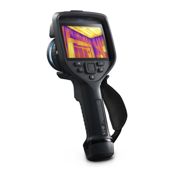
Camera overview 6.1 View from the front 1. Laser distance meter. 2. Infrared lens. 3. Focus ring. 4. Autofocus button. 5. Trigger. 6. Lamp for the digital camera (left and right sides). 7. Digital camera. 8. Attachment point for the hand strap bracket (left and right sides). 9. -
Page 19: View From The Rear
Camera overview 6.2 View from the rear 1. Cover for the USB connector and memory card slot. 2. Microphone. 3. Speaker. 4. Touch-screen LCD. 5. Image archive button. 6. Programmable button. 7. Button to operate the laser. 8. Back button. 9. -
Page 20: Laser Transmitter And Receiver
Camera overview 6.3.1 Laser transmitter and receiver 1. Laser transmitter. 2. Laser receiver. 6.3.2 Difference in position This figure shows the difference in position between the laser transmitter and the optical center of the infrared lens. 2. This item is dependent on the camera model. #T810587;... -
Page 21: Laser Warning Label
Camera overview 6.3.3 Laser warning label A laser warning label with the following information is attached to the camera: 6.3.4 Laser rules and regulations Wavelength: 650 nm. Maximum output power: 1 mW. This product complies with 21 CFR 1040.10 and 1040.11 except for deviations pursuant to Laser Notice No. -
Page 22: Status Icons And Indicators
If the icon is grey, the camera cannot find a GPS signal. External infrared window compensation is enabled. The camera is paired with a FLIR Ignite account. The camera is paired, but does not have contact with FLIR Ignite (no internet connection). A Bluetooth headset is connected. -
Page 23: Image Overlay Information
5. Ignite upload button: Touch to enable/disable automatic upload of images and videos. See also section 9.5 Automatic upload. Note If the camera is not paired with a FLIR Ignite account, you will be prompted to sign in to FLIR Ignite before you can enable automatic upload. -
Page 24: Navigating The Menu System
Camera overview 6.5 Navigating the menu system You can navigate the menu system in two ways: • Using your finger or a stylus pen specially designed for capacitive touch usage. • Using the navigation pad and the back button 6.5.1 Navigating using the navigation pad You navigate the menu system by using the navigation pad and the back button: •... -
Page 25: Handling The Camera
Handling the camera 7.1 Charging the battery 7.1.1 General • Before starting the camera for the first time, charge the battery for 2 hours using the stand-alone battery charger. • Select a mains socket that is near the equipment and easily accessible. 7.1.2 Using the stand-alone battery charger to charge the battery 1. -
Page 26: Charging The Battery Using A Usb Cable Connected To A Computer
Handling the camera 4. Connect the USB connector of the USB battery charger to the USB-C connector in the connector bay of the camera. 5. To check the status of the battery charging, do one of the following: • If the camera is turned on: Place your finger at the top of the screen and swipe down. -
Page 27: Removing The Battery
Handling the camera 2. Connect a USB cable to the USB-C connector in the connector bay. Connect the oth- er end of the USB cable to the computer. Note • To charge the camera, the computer must be turned on. •... -
Page 28: Adjusting The Thermal Camera Focus
Handling the camera 7.4 Adjusting the thermal camera focus It is very important to adjust the focus correctly. Incorrect focus adjustment affects how the image modes work. It also affects the temperature measurement. You can adjust the camera focus by rotating the focus ring or by pushing the autofocus button. -
Page 29: Continuous Autofocus
Handling the camera Note • You can also assign the autofocus function to the programmable button. For more in- formation, see section 7.9 Programmable button. • Autofocus is not supported by all camera models. 7.4.2.1 Autofocus method When autofocusing, the camera can use one of the following focus methods: •... -
Page 30: Operating The Laser Distance Meter
Handling the camera Note • Before you can enable continuous autofocus, you need to enable the laser and select laser as focus method. See section 7.4.2.1 Autofocus method. • When continuous autofocus is enabled, it is not possible to manually adjust the focus by rotating the focus ring. -
Page 31: Measuring Areas
Handling the camera 7.6 Measuring areas 7.6.1 General Note The availability of this feature is dependent on the camera model. The distance measured by the laser distance meter can be used as the basis for area calculations. A typical application is to estimate the size of a damp stain on a wall. To measure the area of a surface, you need to lay out a box or circle measurement tool on the screen. -
Page 32: Connecting External Devices And Storage Media
Handling the camera 5. Hold the camera perpendicular to the target. Push and hold the laser button 6. The calculated area is displayed in the result table. 7.7 Connecting external devices and storage media You can connect the following external devices and media to the camera: •... -
Page 33: Related Topics
Note Moving a file using a drag-and-drop operation does not delete the file in the camera. • Import the images into a FLIR Thermography software. 7.8.1 Related topics You can also set up the camera to upload images for storage online, see section 9 Cloud connectivity, page 46. -
Page 34: Programmable Button
Handling the camera 7.9 Programmable button You can assign different functions to the programmable button. You can, for example, use the programmable button to easily switch between two settings you use often. You can also choose to define two different setups for saving and previewing: the ordinary setup for the trigger (which is defined by the Save options and storage settings, see sec- tion 23.5 Save options &... -
Page 35: Using The Camera Lamp As A Flash
Handling the camera • Switch Auto <> Manual temperature scale: Switch between automatic or manual im- age adjustment mode. For more information, see section 11.3 Adjusting the infrared image. • Autofocus : One-shot autofocus of the infrared camera. • Continuous autofocus : Switch between the enabled/disabled continuous autofocus functions. -
Page 36: Hand Strap
Handling the camera 2. Select (Settings) and push the navigation pad. This displays the Settings menu. 3. Use the navigation pad to select Device settings > Lamp & laser. 4. To use the camera lamp as a flash, do one of the following: •... -
Page 37: Mounting The Hand Strap
Handling the camera 7.11.1 Mounting the hand strap 1. Fit the upper part of the hand strap into the bracket. 2. Fit the bracket in place on the camera and tighten the screw with the supplied Torx key. #T810587; r. AC/84076/84376; en-US... - Page 38 Handling the camera 3. Thread the loose strap through the attachment point at the base of the camera. Se- cure the strap with the hook-and-loop fastener. #T810587; r. AC/84076/84376; en-US...
-
Page 39: Lanyard Strap
Handling the camera 7.12 Lanyard strap To mount the lanyard strap, do the following: 1. Remove the camera battery. #T810587; r. AC/84076/84376; en-US... -
Page 40: Wrist Strap
Handling the camera 2. Starting with the FLIR logo part, thread the lanyard strap through the attachment point at the base of the camera. 3. Pull the entire lanyard strap through the attachment point until it stops. 7.13 Wrist strap The wrist strap can also be used to attach a carabiner to the camera. -
Page 41: Front Protection
Handling the camera 2. Fold the wrist strap. Make sure that the part with the FLIR logo faces away from the bend. 3. Thread the bent wrist strap through the attachment point at the base of the camera. 4. Pull the entire wrist strap through the attachment point until it stops. -
Page 42: Changing Camera Lenses
Handling the camera 7.15 Changing camera lenses Applicability: Camera models with an exchangeable lens. Note If the new lens has not been used with the camera before, the lens–camera com- bination must be calibrated after the lens has been mounted. See section 7.16 Calibrat- ing the lens–camera combination for information on how to do this. - Page 43 Handling the camera 2. Carefully pull out the lens. 3. The infrared detector is now fully exposed. Do not touch this surface. If you see dust on the detector, follow the instructions in 24.3 Infrared detector. #T810587; r. AC/84076/84376; en-US...
- Page 44 Handling the camera 4. Make sure that the inner ring of the camera lens is fully in its open position. • Correct: The tooth (1) is in its end position at the black stop pin (2). • Wrong: You must rotate the inner ring until the tooth (1) reaches the black stop pin (2).
-
Page 45: Calibrating The Lens-Camera Combination
Before a new lens can be used with the camera, the lens–camera combination must be calibrated. This is a process that previously had to be performed by a FLIR service department, but for the FLIR Exx series the calibration can be performed by the user. This feature is called AutoCal. -
Page 46: Autocal Procedure
Handling the camera 7.16.2 AutoCal procedure 1. Dip the calibration target in water for 1 second and let the excess drip off. 2. Tape or hang the calibration target on a wall. 3. Mount the new lens on the camera according to the procedure in section 7.15 Changing camera lenses. -
Page 47: Calibrating The Compass
Handling the camera 4. From a distance of 2 m (6.6 ft.), aim the camera toward the crosshair, using the laser pointer. The camera will take a picture automatically. Note Make sure the camera’s optical path is perpendicular to the calibration target. See the image below. -
Page 48: Saving And Working With Images
The image *.jpg file is fully radiometric and saved lossless, which enables full post-proc- essing in image analysis and reporting software from FLIR Systems. There is also a reg- ular *.jpg component (lossy) for convenient viewing in non-FLIR Systems software (e.g., Microsoft Explorer). -
Page 49: Saving An Image
Saving and working with images Some FLIR Thermography software has the ability to process UltraMax images. Other FLIR software will treat the image as a regular image. To configure the camera for UltraMax, select (Settings) > Save options & storage >... -
Page 50: Opening A Saved Image
Saving and working with images 3. To edit the image, push the navigation pad. This displays a context menu. For editing instructions, see section 8.5 Editing a saved image. 4. Do one of the following: • To save the image, pull the trigger. •... -
Page 51: Related Topics
Saving and working with images 8. Push the navigation pad. This displays a context menu. • Select (Cancel) to exit edit mode. • Select (Measurement parameters) to change the global parameters. • Select (Image mode) to change the image mode. •... -
Page 52: Resetting The Image Counter
Saving and working with images 8.9 Resetting the image counter You can reset the numbering of the image filenames. Note To prevent image files being overwritten, the new counter value will be based on the highest existing filename number in the image archive. To ensure that the counter is reset to 0001, insert an empty memory card before resetting the counter. -
Page 53: Cloud Connectivity
FLIR Ignite is a cloud storage service for thermal images. Upload images from your cam- era and your data will be instantly available across all your devices. With FLIR Ignite you can edit images and create basic reports. You can also share images with colleagues and clients and invite team members to work in the same folder and files. -
Page 54: Creating A Flir Ignite Account
6. Sign in to your FLIR Ignite account. 9.5 Automatic upload You can set up the camera to automatically upload images and videos to your FLIR Ignite account. When automatic upload is enabled, new images and videos will automatically be up- loaded when the camera is connected to the internet and paired with FLIR Ignite. -
Page 55: Uploading Folders
6. On the right toolbar, select the icon. 9.7 Accessing FLIR Ignite You can access FLIR Ignite from a browser on your desktop, tablet, or mobile device. To access FLIR Ignite, go to https://ignite.flir.com. For more information, refer to the FLIR Ignite user manual. -
Page 56: Working With The Image Archive
Working with the image archive 10.1 General When you save an image or video clip, the camera stores the image/video file in the im- age archive on the memory card. You can open an image in the image archive and, for example, select another image mode, apply color alarms, and add measurement tools. -
Page 57: Renaming A Folder
6. Select the destination folder for the selected items and push the navigation pad. 10.7 Uploading files and folders You can manually upload images, videos, and folders to your FLIR Ignite account when the camera is connected to the internet. For more information, see section 9.6 Manual upload. -
Page 58: Deleting An Image Or Video File
Working with the image archive 4. On the right toolbar, select the icon and push the navigation pad. This displays a dialog box. 5. To delete the folder, select Delete and push the navigation pad. 10.9 Deleting an image or video file You can delete an image or video file from the image archive. -
Page 59: Achieving A Good Image
Achieving a good image 11.1 General A good image depends on several different functions and settings, although some func- tions and settings affect the image more than others. These are the functions and settings that you need to experiment with: •... - Page 60 Achieving a good image In automatic mode, the camera continuously adjusts the level and span for the best im- age presentation. The colors are distributed based on the thermal content of the image (histogram color distribution). The temperature scale to the right of the screen shows the upper and lower temperatures of the current span.
-
Page 61: Auto Adjustment Region
Achieving a good image Automatic Manual 11.3.2 Auto adjustment region When you auto-adjust a thermal image, you adjust it for the best image brightness and contrast. This means that the color information is distributed over the existing tempera- tures of the image. In some situations, the image may contain very hot or very cold areas outside your area of interest. -
Page 62: Manual Adjustment By Using The Navigation Pad
Achieving a good image 2. Select (Temperature scale) and push the navigation pad. This displays a submenu. 3. Select (Manual) and push the navigation pad. 4. To simultaneously change the temperature scale minimum and maximum limits, place your finger on the screen and move it up/down. 5. -
Page 63: Manual Adjustment In Level, Span Mode
Achieving a good image 11.3.5 Manual adjustment in Level, Span mode Note This procedure assumes that you have configured the camera for manual image adjustments in Level, Span mode. Select Settings > Device settings > User interface op- tions > Manual adjustment mode = Level, Span. Follow this procedure: 1. - Page 64 Achieving a good image This table explains the different types of color palettes. Iron Arctic Rainbow Rainbow high contrast White hot Black hot Lava Follow this procedure: 1. Push the navigation pad to display the menu system. 2. Select (Color) and push the navigation pad. This displays a submenu. 3.
-
Page 65: Changing The Measurement Parameters
Achieving a good image 4. Push the navigation pad to confirm and exit the menu mode. 11.6 Changing the measurement parameters For accurate measurements, it is important to set the measurement parameters: • Emissivity. • Reflected temperature. • Object distance. •... - Page 66 Achieving a good image You can choose to hide all camera overlay by pressing the programmable button. Image with camera overlay and image overlay Image with all overlay hidden. information. Follow this procedure: 1. Push and hold the programmable button. This displays the Programmable button menu.
-
Page 67: Working With Image Modes
• For the Thermal MSX, Thermal, and Picture in picture image modes, all thermal and visual information is stored when an image is saved. This means that you can edit the image later, in the image archive or in a FLIR Thermography software, and select any of the image modes. -
Page 68: Selecting An Image Mode
Working with image modes Thermal MSX Thermal Digital camera Picture in picture 12.3 Selecting an image mode Follow this procedure: 1. Push the navigation pad to display the menu system. 2. Select (Image mode) and push the navigation pad. This displays a submenu. 3. -
Page 69: Working With Measurement Tools
Working with measurement tools 13.1 General To measure a temperature, you can use one or more measurement tools, e.g., a spot- meter or a box. 13.2 Adding/removing measurement tools Follow this procedure: 1. Push the navigation pad to display the menu system. 2. -
Page 70: Moving And Resizing A Measurement Tool
Working with measurement tools 2. Select (Measurement) and push the navigation pad. This displays a submenu. 3. Use the navigation pad to select (User preset 1) or (User preset 2). 4. Push and hold the center of the navigation pad. This displays the Edit user preset menu. -
Page 71: Moving And Resizing A Box, Circle, Or Line Tool
Working with measurement tools 5. When completed, push the navigation pad and select (Done). 6. Push the navigation pad to confirm and exit the menu mode. 13.4.3 Moving and resizing a box, circle, or line tool Note You can also move and resize the measurement tool by touching the screen. Follow this procedure: 1. -
Page 72: Recommended Values
Working with measurement tools opposite of emissivity is reflectivity. The emissivity determines how much of the radia- tion originates from the object as opposed to being reflected by it. Note There is an Emissivity mode setting, which you can use to enter the emissivity by material instead of by value. -
Page 73: Displaying Values In The Result Table
Working with measurement tools 13.5.4.2 Changing local parameters You can change the local parameters for a measurement tool. A P next to the measurement tool on the screen indicates that local parameters have been activated for the tool. Follow this procedure: 1. -
Page 74: Displaying A Graph
Working with measurement tools 8. Select (Done) and push the navigation pad. 13.7 Displaying a graph For the line tool, you can set the camera to display a graph. Note You can display a graph when previewing an image, when defining user presets, or when editing an image in the archive. -
Page 75: Setting A Measurement Alarm
Working with measurement tools 13.9 Setting a measurement alarm 13.9.1 General You can make the camera trigger an alarm when certain measurement conditions are met. 13.9.2 Types of alarm You can choose between the following alarm types: • Above: Triggers an alarm when the temperature is above the preset alarm temperature. - Page 76 Working with measurement tools 4. In the dialog box, you can define the settings for the alarm. • Alarm condition: The condition that triggers the alarm. Applicable values are Above, Below, or Off. • Select measurement: Applicable settings are the values you have previously de- fined (Max, Min, and/or Avg).
-
Page 77: Working With Color Alarms And Isotherms
Working with color alarms and isotherms 14.1 Color alarms By using color alarms (isotherms), anomalies can easily be discovered in an infrared im- age. The isotherm command applies a contrasting color to all pixels with a temperature above, below, or between the set temperature levels. The camera also features isotherm types that are specific to the building trade: condensation and insulation alarms. -
Page 78: Setting Up Above, Below, And Interval Alarms
Working with color alarms and isotherms 14.1.1 Setting up above, below, and interval alarms 1. Push the navigation pad to display the menu system. 2. Select (Color) and push the navigation pad. This displays a submenu. 3. Use the navigation pad to select one of the following: •... - Page 79 Working with color alarms and isotherms 4. Push the navigation pad. This displays a dialog box where you can define the settings for the alarm. For the Condensation alarm, the following parameters can be set: • Atmospheric temperature: The current atmospheric temperature. •...
-
Page 80: Annotating Images
Annotations are added to the image file and can be viewed and edited in the camera or in a FLIR Thermography software. • You can set the camera to display annotation tools when an image is saved. Select (Settings) >... -
Page 81: Creating A Text Comment Table Template
FLIR Thermography software. 15.3.1.1 Manually creating a table template A text comment file (*.tcf) is an annotation format that is proprietary to FLIR Systems. It defines a table structure that can be used to add text table annotations to FLIR images. -
Page 82: Adding A Voice Annotation
A voice annotation is an audio recording that is saved to the infrared image file. The re- cording can be played back in the camera, and in image analysis and reporting software from FLIR Systems. The voice annotation is recorded using the built-in microphone. You can also use a Blue- tooth-enabled headset. - Page 83 Annotating images 6. (Optional step.) Push the navigation pad. This displays a context menu. Do one or more of the following: • To change the color of the sketch tools, select (Draw) and push the navigation pad. Select the color and push the navigation pad. •...
-
Page 84: Programming The Camera (Time-Lapse)
Programming the camera (time- lapse) Note The availability of this feature is dependent on the camera model. You can program the camera to save images periodically (time-lapse). Follow this procedure: 1. Push the navigation pad to display the menu system. 2. -
Page 85: Recording Video Clips
• Radiometric storage (*csq) : A *.csq file supports full radiometry but is only supported by FLIR Systems software. The file does not include any visual image information. With this setting, only Thermal image mode is supported when recording video. If any other image mode is active when Video recording mode is selected, the camera will auto-switch to Thermal image mode. -
Page 86: Inspection Route
1. Prepare the inspection route file, using one of the following methods: • The FLIR Thermal Studio application. • Your own solution. The FLIR Thermal SDK can be used to build your own export/ import software or to interface your existing asset management system. -
Page 87: Drop-Down Menu
Inspection Route The Inspection Route overlay consists of the following parts: • Back arrow Tap to go to the previous inspection point. • Current point indicator ◦ Displays the name of the current inspection point. ◦ Displays an image icon if there is an image saved for the inspection point. ◦... -
Page 88: Performing An Inspection
Inspection Route Figure 18.1 Figure 18.1 shows an example of the inspection list: • The first inspection route is completed and locked, which is indicated by the check mark to the right. • The second inspection route has started. It includes a total of 91 inspection points, and one of them has been inspected. -
Page 89: Capturing Inspection Data
Inspection Route 4. Activate the Inspection Route function by selecting (Settings) > Save options & storage > Inspection route, and then toggle the Inspection route switch. 5. The camera is now ready. 18.3.2 Capturing inspection data Once the camera is prepared, the inspection can start. Note You can turn off the camera in the middle of an inspection. -
Page 90: Editing Inspection Point Data
Inspection Route 8. When you have completed the inspection, transfer the inspection results to a com- puter for post-processing. For more information, see section 18.3.9 Transferring in- spection results. 18.3.3 Editing inspection point data You can edit the data for the inspection point displayed by the current point indicator. To go to another inspection point, use the back or next arrow or select the inspection point from the inspection list, see section 18.3.7 Inspection list. -
Page 91: Inspection List
• The DCIM folder includes folders with the images for each route. You can upload the inspection results to your FLIR Ignite account or transfer the result files manually using the USB cable or the memory card. You can also open the results from the memory card and save them to a computer using FLIR Thermal Studio. -
Page 92: Configuration
Inspection Route 18.3.9.2 Move results manually If you transfer the inspection results manually to a computer, you must move both the in- spection route file (.xml) and the images in their route folders. It is important to maintain the DCIM folder structure. 1. -
Page 93: Creating An Inspection Route
The inspection route file can be created using one of the following methods: • The FLIR Thermal Studio application. • Your own solution. The FLIR Thermal SDK can be used to build your own export/im- port software or to interface your existing asset management system. - Page 94 Inspection Route 3. Select one of the following: • Create an example Inspection route: This creates an example XML file with a mul- ti-level structure on the memory card. • Create an empty Inspection route: This creates a basic XML file on the memory card.
-
Page 95: Screening Alarm
Screening alarm The screening alarm can be used to detect temperature anomalies in a series of in- spected objects in a similar/fixed setup. 19.1 General The basics of the screening alarm is to first build up a base of reference temperature samples. -
Page 96: Record Reference Samples
Screening alarm 19.2.2 Record reference samples Before the screening can start, you must record reference samples. These are used to calculate the reference temperature average. You record the reference samples by screening 10 inspection objects. Make sure these objects have a normal temperature. 1. -
Page 97: Configuring Wi-Fi
Configuring Wi-Fi Depending on your camera configuration, you can connect the camera to a wireless local area network (WLAN) using Wi-Fi, or let the camera provide Wi-Fi access to other devices. You can connect the camera in two different ways: •... -
Page 98: Pairing Bluetooth Devices
• You can remove a device by selecting the device and then selecting Unpair device. • After adding a METERLiNK device, such as the FLIR MR77 or FLIR DM93, the result from the meter will be visible in the result table and stored with the images. For more information, see section 22 Fetching data from external FLIR meters. -
Page 99: Fetching Data From External Flir Meters
The live value is displayed with a dotted outline. If the screen display for values is full, it is still possible to add more values from the FLIR meter. Added values are then indicated by a box with a number that counts up each time a new value is added. -
Page 100: Typical Moisture Measurement And Documentation Procedure
Fetching data from external FLIR meters 22.4 Typical moisture measurement and documentation procedure The following procedure can form the basis for other procedures using FLIR meters and infrared cameras. 1. Use the infrared camera to identify any potential damp areas behind walls and ceilings. -
Page 101: Camera Settings
• Save options & storage. • Device settings. 23.1 FLIR Ignite Select FLIR Ignite and follow the on-screen instructions to sign in to your FLIR Ignite account. After sign in, the following is displayed: • The FLIR Ignite user account that the camera is paired with. -
Page 102: Camera Temperature Range
◦ Radiometric storage (*.csq) : A CSQ file supports full radiometry but is only sup- ported by FLIR Systems software. The file does not include any visual image infor- mation. With this setting, only Thermal image mode is supported when recording video. -
Page 103: Device Settings
Camera settings Example: FLIR0001. (When the counter has reached 9999, the file name will change to IR_yyyyy.jpg.) ◦ Date prefix: A prefix will be added to the filename, including the date and the text “IR_” for images and “MOV_” for videos. Examples: IR_2015-04-22_0002 and MOV_2015-04-22_0003. - Page 104 Camera settings • Geolocation: This submenu includes the following settings: ◦ GPS: This setting is used to enable/disable the GPS. ◦ Compass: This setting is used to enable/disable the compass and to calibrate the compass. For more information, see section 7.17 Calibrating the compass. •...
- Page 105 Camera settings ◦ Register camera...: This will start the registration wizard. For more information, see section 3.2 Register your camera. ◦ Licenses: Open-source license information. • Regulatory: Displays regulatory information about the camera. No changes can be made. #T810587; r. AC/84076/84376; en-US...
-
Page 106: Cleaning The Camera
Cleaning the camera 24.1 Camera housing, cables, and other items Use one of these liquids: • Warm water • A weak detergent solution Equipment: • A soft cloth Follow this procedure: 1. Soak the cloth in the liquid. 2. Twist the cloth to remove excess liquid. 3. - Page 107 Cleaning the camera Note • This section only applies to cameras where removing the lens exposes the infrared detector. • In some cases the dust cannot be removed by following this procedure: the infrared detector must be cleaned mechanically. This mechanical cleaning must be carried out by an authorized service partner.
-
Page 108: Mechanical Drawings
Mechanical drawings [See next page] #T810587; r. AC/84076/84376; en-US... -
Page 110: Ce Declaration Of Conformity
CE Declaration of conformity The full text of the Declaration of conformity is available at the following internet address: http://support.flir.com/resources/5v82. #T810587; r. AC/84076/84376; en-US... -
Page 111: About Calibration
27.3 Camera calibration at FLIR Systems Without calibration, an infrared camera would not be able to measure either radiance or temperature. At FLIR Systems, the calibration of uncooled microbolometer cameras with a measurement capability is carried out during both production and service. Cooled cam- eras with photon detectors are often calibrated by the user with special software. -
Page 112: The Differences Between A Calibration Performed By A User And That Performed Directly At Flir Systems
The calibration information, no matter if the calibration is done by FLIR Systems or the user, is stored in calibration curves, which are expressed by mathematical functions. As... -
Page 113: Non-Uniformity Correction
About calibration Calibration is also a prerequisite for adjustment, which is the set of operations carried out on a measuring system such that the system provides prescribed indications corre- sponding to given values of quantities to be measured, typically obtained from measure- ment standards. -
Page 114: About Flir Systems
• Extech Instruments (2007) Figure 28.1 Patent documents from the early 1960s FLIR Systems has three manufacturing plants in the United States (Portland, OR, Boston, MA, Santa Barbara, CA) and one in Sweden (Stockholm). Since 2007 there is also a manufacturing plant in Tallinn, Estonia. -
Page 115: More Than Just An Infrared Camera
28.1 More than just an infrared camera At FLIR Systems we recognize that our job is to go beyond just producing the best infra- red camera systems. We are committed to enabling all users of our infrared camera sys- tems to work more productively by providing them with the most powerful camera–... -
Page 116: Supporting Our Customers
28.3 Supporting our customers FLIR Systems operates a worldwide service network to keep your camera running at all times. If you discover a problem with your camera, local service centers have all the equipment and expertise to solve it within the shortest possible time. - Page 117 Disclaimer Specifications subject to change without further notice. Models and accessories subject to regional market considerations. License procedures may apply. Products described herein may be subject to US Export Regulations. Please refer to exportquestions@flir.com with any questions. Publ. No.: T810587...
Need help?
Do you have a question about the E54-24 and is the answer not in the manual?
Questions and answers