
Related Manuals for ASROCK Rack W790D8UD-1L1N


Summary of Contents for ASROCK Rack W790D8UD-1L1N
- Page 1 W790D8UD-1L1N2T/BCM W790D8UD-1L1N User Manual Version 1.0 Published June 2023 Copyright©2023 ASRock Rack INC. All rights reserved.
- Page 2 In no event shall ASRock Rack, its directors, officers, employees, or agents be liable for any indirect, special, incidental, or consequential damages (including damages for loss of...
- Page 3 INTEL END USER SOFTWARE LICENSE AGREEMENT IMPORTANT - READ BEFORE COPYING, INSTALLING OR USING. LICENSE. Licensee has a license under Intel’s copyrights to reproduce Intel’s Software only in its unmodified and binary form, (with the accompanying documentation, the “Software”) for Licensee’s personal use only, and not commercial use, in connection with Intel-based products for which the Software has been provided, subject to the following conditions: (a) Licensee may not disclose, distribute or transfer any part of the Software, and You agree...
- Page 4 U.S. GOVERNMENT RESTRICTED RIGHTS. The Software is a commercial item (as defined in 48 C.F.R. 2.101) consisting of commercial computer software and commercial computer software documentation (as those terms are used in 48 C.F.R. 12.212), consistent with 48 C.F.R. 12.212 and 48 C.F.R 227.7202-1 through 227.7202-4. You will not provide the Software to the U.S.
- Page 5 ASRock Rack follows the green design concept to design and manufacture our products, and makes sure that each stage of the product life cycle of ASRock Rack product is in line with global environmental regulations. In addition, ASRock Rack disclose the relevant in- formation based on regulation requirements.
-
Page 6: Table Of Contents
Contents Chapter 1 Introduction Package Contents Specifications Unique Features Motherboard Layout Onboard LED Indicators I/O Panel Block Diagram Chapter 2 Installation Screw Holes Pre-installation Precautions Installing the CPU and Heatsink Installation of Memory Modules (DIMM) Expansion Slots (PCI Express Slots) Jumper Setup Onboard Headers and Connectors ATX PSU Power Connections... - Page 7 3.1.1 UEFI Menu Bar 3.1.2 Navigation Keys Main Screen 3.2.1 Motherboard Information 3.2.2 Processor Information 3.2.3 Memory Information OC Tweaker 3.3.1 CPU Configuration 3.3.2 DRAM Configuration 3.3.3 Voltage Configuration 3.3.4 FIVR Configuration Advanced Screen 3.4.1 CPU Configuration 3.4.2 Platform Power Configuration 3.4.3 Chipset Configuration 3.4.4 PCH-FW Configuration 3.4.5 Storage Configuration...
- Page 8 3.4.13 Runtime Error Logging 3.4.14 Workstation ME Configuration 3.4.15 Network Stack Configuration 3.4.16 Intel® VMD technology 3.4.17 Driver Health 3.4.18 All CPU Informaton 3.4.19 Emulation Configuration 3.4.20 Tls Auth Configuration 3.4.21 MEBx 3.4.22 Instant Flash Security 3.5.1 Key Management Event Logs Boot Screen 3.7.1 Server Mgmt...
- Page 9 Chapter 5 Troubleshooting Troubleshooting Procedures Technical Support Procedures Returning Merchandise for Service...
-
Page 11: Chapter 1 Introduction
In case any modifications of this manual occur, the updated version will be available on ASRock Rack website without further notice. Find the latest memory and CPU support lists on ASRock Rack website as well. ASRock Rack’s Website: www.ASRockRack.com About this motherboard technical support, please visit the website for specific informa- tionhttp://www.asrockrack.com/support/... -
Page 12: Specifications
1.2 Specifications W790D8UD-1L1N2T/BCM / W790D8UD-1L1N Physical Status Form Factor Deep Micro-ATX Dimension 10.4'' x 10.5'' (264 x 266 mm) Processor System Supports Intel® Xeon® W-2400 and W-3400 series processors Socket Single Socket LGA 4677 Thermal Design ~350W Power (TDP) Support O.C. - Page 13 W790D8UD-1L1N2T/BCM: 1 RJ45 Dedicated IPMI LAN IPMI Dedicated GLAN port by Realtek RTL8211F W790D8UD-1L1N: NA System BIOS BIOS type AMI 256Mb SPI Flash ROM Features Plug and Play, ACPI 5.0 and above compliance wake up events, SMBIOS 2.3 and above, ASRock Rack Instant Flash...
- Page 14 LED, locate, SMBus System panel 1 (9-pin): power switch, reset switch, system power LED, HDD header activity LED NMI button W790D8UD-1L1N2T/BCM: 1 LAN3/LAN4 LED W790D8UD-1L1N: NA header Speaker header 1 (4-pin) Buzzer Fan header 7 (4-pin) Thermal sensor header...
- Page 15 W790D8UD-1L1N W790D8UD-1L1N2T/BCM Enviroment Operating 10 - 35°C (50 - 95 degF) temperature Non-operating -40 - 70°C (-40 - 158degF) temperature NOTE: Please refer to the website for the latest specifications. This motherboard supports Wake from on Board LAN. To use this function, please make sure that the “Wake on Magic Packet from power off state”...
-
Page 16: Unique Features
. With this utility, press the <F6> key during the POST or the <F2> key to enter into the BIOS setup menu to access ASRock Rack Instant Flash. Just launch this tool and save the new BIOS file to the USB flash drive, floppy disk or hard drive, then update the BIOS only in a few clicks without preparing an additional floppy diskette or other complicated flash utility. -
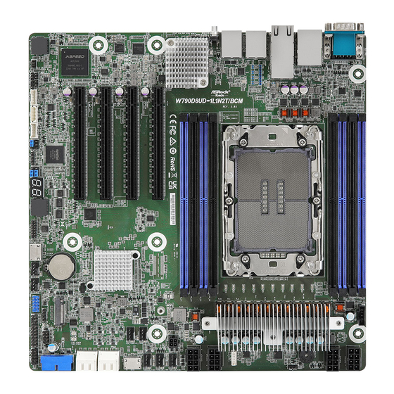
Page 17: Motherboard Layout
W790D8UD-1L1N W790D8UD-1L1N2T/BCM 1.4 Motherboard Layout W790D8UD-1L1N2T/BCM : 26.4 cm (10.4 in) DDR5_B1 PSU_SMB1 DDR5_B2 ATX12V2 DDR5_A1 DDR5_A2 ATX12V4 BUZZER1 USB 3.2 Gen1 T: USB3_1 IPMI_LAN1 B: USB3_2 PWM_CFG1 LAN2 LAN1 CPU1 LAN3 RAID_1 LAN4 ATX12V1 UID1 DDR5_E2 DDR5_E1 ATX12V3 DDR5_F2... - Page 18 Description 2 x 288-pin DDR5 DIMM Slots (DDR5_A1, DDR5_B1)* 2 x 288-pin DDR5 DIMM Slots (DDR5_A2, DDR5_B2)* PSU SMBus Header (PSU_SMB1) ATX 12V Power Connector (ATX12V2) ATX 12V Power Connector (ATX12V4) PWM Configuration Header (PWM_CFG1) Virtual RAID On CPU Header (RAID_1) ATX 12V Power Connector (ATX12V1) ATX 12V Power Connector (ATX12V3) Micro-Fit ATX 4Pin Power Connector (ATX4PIN1)
- Page 19 W790D8UD-1L1N W790D8UD-1L1N2T/BCM Description Backplane PCI Express Hot-Plug Connector (CPU0_HSBP1) Non Maskable Interrupt Button (NMI_BTN1) PCI Express 5.0 x16 Slot (PCIE4) PCI Express 5.0 x16 Slot (PCIE5) PCI Express 5.0 x16 Slot (PCIE6) PCI Express 5.0 x16 Slot (PCIE7) 2 x 288-pin DDR5 DIMM Slots (DDR5_E1, DDR5_F1)*...
- Page 20 W790D8UD-1L1N : 26.4 cm (10.4 in) DDR5_B1 PSU_SMB1 DDR5_B2 ATX12V2 DDR5_A1 DDR5_A2 ATX12V4 BUZZER1 USB 3.2 Gen1 T: USB3_1 B: USB3_2 PWM_CFG1 CPU1 LAN3 RAID_1 LAN4 ATX12V1 UID1 DDR5_E2 DDR5_E1 ATX12V3 DDR5_F2 DDR5_F1 ATX4PIN1 FAN1 PCIE7 FAN2 FAN3 FAN4 PCIE6...
- Page 21 W790D8UD-1L1N W790D8UD-1L1N2T/BCM Description 2 x 288-pin DDR5 DIMM Slots (DDR5_A1, DDR5_B1)* 2 x 288-pin DDR5 DIMM Slots (DDR5_A2, DDR5_B2)* PSU SMBus Header (PSU_SMB1) ATX 12V Power Connector (ATX12V2) ATX 12V Power Connector (ATX12V4) PWM Configuration Header (PWM_CFG1) Virtual RAID On CPU Header (RAID_1)
- Page 22 Description PCI Express 5.0 x16 Slot (PCIE5) PCI Express 5.0 x16 Slot (PCIE6) PCI Express 5.0 x16 Slot (PCIE7) 2 x 288-pin DDR5 DIMM Slots (DDR5_E1, DDR5_F1)* 2 x 288-pin DDR5 DIMM Slots (DDR5_E2, DDR5_F2)* LGA 4677 CPU Socket (CPU1) *For DIMM installation and configuration instructions, please see p.25 (Installation of Memory Modules (DIMM)) for more details.
-
Page 23: Onboard Led Indicators
W790D8UD-1L1N W790D8UD-1L1N2T/BCM 1.5 Onboard LED Indicators Item Status Description LED_FAN1 FAN1 failed LED_FAN2 FAN2 failed LED_FAN3 FAN3 failed LED_FAN4 FAN4 failed LED_FAN5 FAN5 failed SB_PWR1 Green STB PWR ready LED_FAN6 FAN6 failed LED_FAN7 FAN7 failed BMC heartbeat LED BMC_LED1 Green... -
Page 24: I/O Panel
USB 3.2 Gen1 Ports (USB3_1_2) 2.5G LAN RJ-45 Port (LAN4)*** LAN RJ-45 Port (IPMI_LAN1)* UID Switch (UID1) 10G LAN RJ-45 Port (LAN1)**** W790D8UD-1L1N: No. Description No. Description Serial Port (COM1) 2.5G LAN RJ-45 Port (LAN4)*** USB 3.2 Gen1 Ports (USB3_1_2) - Page 25 W790D8UD-1L1N W790D8UD-1L1N2T/BCM LAN Port LED Indications *There are two LEDs on each LAN port. Please refer to the table below for the LAN port LED indications. ACT/LINK LED SPEED LED LAN Port IPMI LAN Port LED Indications ( W790D8UD-1L1N2T/BCM only)
- Page 26 ***There are two LEDs on each LAN port. Please refer to the table below for the LAN port LED indications. ACT/LINK LED SPEED LED LAN Port 2.5G LAN Port LED Indications Activity / Link LED Speed LED Status Description Status Description No Link 10Mbps connection or no...
-
Page 27: Block Diagram
W790D8UD-1L1N W790D8UD-1L1N2T/BCM 1.7 Block Diagram W790D8UD-1L1N2T/BCM... - Page 28 W790D8UD-1L1N...
-
Page 29: Chapter 2 Installation
W790D8UD-1L1N W790D8UD-1L1N2T/BCM Chapter 2 Installation This is a deep micro-ATX form factor (10.4” x 10.5”) motherboard. Before installing the motherboard, study the configuration of the chassis to ensure that the motherboard fits into it. Make sure to unplug the power cord before installing or removing the motherboard. Failure to do so may cause physical injuries and motherboard damages. -
Page 30: Pre-Installation Precautions
2.2 Pre-installation Precautions Take note of the following precautions before installing motherboard components or change any motherboard settings. 1. Unplug the power cord from the wall socket before touching any components. 2. To avoid damaging the motherboard’s components due to static electricity, NEVER place the motherboard directly on the carpet or the like. -
Page 31: Installing The Cpu And Heatsink
W790D8UD-1L1N W790D8UD-1L1N2T/BCM 2.3 Installing the CPU and Heatsink Socket Dust Cover CPU Carrier... - Page 33 W790D8UD-1L1N W790D8UD-1L1N2T/BCM...
- Page 34 CPU Carrier...
- Page 35 W790D8UD-1L1N W790D8UD-1L1N2T/BCM Heatsink CPU Carrier Socket...
-
Page 37: Installation Of Memory Modules (Dimm)
W790D8UD-1L1N W790D8UD-1L1N2T/BCM 2.4 Installation of Memory Modules (DIMM) This motherboard provides eight 288-pin DDR5 (Double Data Rate 5) DIMM slots, and supports Dual Channel Memory Technology. 1. For Dual channel configuration, it always needs to install identical (the same brand, speed, size and chip-type) DDR5 DIMM groups. -
Page 39: Expansion Slots (Pci Express Slots)
W790D8UD-1L1N W790D8UD-1L1N2T/BCM 2.5 Expansion Slots (PCI Express Slots) There are 4 PCI Express slots on this motherboard. PCIE slot: PCIE4 (PCIE 5.0 x16 slot, from CPU1) is used for PCI Express x16 lane width cards. PCIE5 (PCIE 5.0 x16 slot, from CPU1) is used for PCI Express x16 lane width cards. -
Page 40: Jumper Setup
2.6 Jumper Setup The illustration shows how jumpers are setup. When the jumper cap is placed on the pins, the jumper is “Short”. If no jumper cap is placed on the pins, the jumper is “Open”. The illustration shows a 3-pin jumper whose pin1 and pin2 are “Short” when a jumper cap is placed on these 2 pins. -
Page 41: Onboard Headers And Connectors
W790D8UD-1L1N W790D8UD-1L1N2T/BCM 2.7 Onboard Headers and Connectors Onboard headers and connectors are NOT jumpers. Do NOT place jumper caps over these headers and connectors. Placing jumper caps over the headers and connectors will cause permanent damage to the motherboard. System Panel Header... - Page 42 Auxiliary Panel Header This header supports multiple (18-pin AUX_PANEL1) functions on the front panel, (see p.7, No. 23) i nc lud i ng t he f ront pa nel SMB, internet status indicator and chassis intrusion pin. A. Front panel SMBus connecting pin (6-1 pin FPSMB) This header allows user to connect SMBus (System Management Bus) equipment.
- Page 43 W790D8UD-1L1N W790D8UD-1L1N2T/BCM Backplane PCI Express This header is used for the hot Hot-Plug Connector plug feature of HDDs on the (5-pin CPU0_ HSBP1) backplane. P0_HP_ALERT_L CPU_HP_SDA (see p.7, No. 36) CPU_HP_SCL H_SCLOCK1 Serial General Purpose This header supports Serial H_SLOAD1...
- Page 44 Serial ATA3 Connectors The SATA3 DOM Right-Angle: connector supports (SATA_0: both a SATA DOM see p.7, No. 17)(Upper) (Disk-On-Module) and (SATA_1: a SATA data cable for see p.7, No. 17)(Lower) internal storage device. (SATA_2: see p.7, No. 18)(Upper) (SATA_3: see p.7, No. 18)(Lower) BMC_SMB_PRESENT_1_N BMC SMB Header These headers are used for the...
- Page 45 W790D8UD-1L1N W790D8UD-1L1N2T/BCM OCuLink Connectors Please connect PCIE SSDs to Right-Angle: these connectors. O CU2 O CU1 (OCU1) (see p.7, No. 15) (OCU2) (see p.7, No. 28) Chassis Speaker Header Please connect the chassis SPEAKER DUMMY (4-pin SPEAKER1) speaker to this header.
- Page 46 IntA_P_D+ USB 3.2 Gen1 Header Besides four default USB 3.2 IntA_P_D- Right-Angle: ports on the I/O panel, there IntA_P_SSTX+ IntA_P_SSTX- (19-pin USB3_3_4) is one USB 3.2 header on this IntA_P_SSRX+ (see p.7, No. 20) motherboard. This USB 3.2 IntA_P_SSRX- Vbus header can support two USB 3.2 ports.
- Page 47 W790D8UD-1L1N W790D8UD-1L1N2T/BCM Virtual RAID On CPU This connector supports Intel® Header Virtual RAID on CPU and VROC RAID KEY (4-pin RAID_1) NVME/AHCI RAID on CPU +3VSB (see p.7, No. 7) PCIE. With the introduction of the Intel VROC product, there are three modes of operation:...
-
Page 48: Atx Psu Power Connections
2.8 ATX PSU Power Connections This motherboard supports ATX power input. Please refer to the table below for the required connections between the motherboard and the power supply. Connector ATX PSU 12V 8pin ATX 4pin (with the bundled ATX 24pin-to-4pin converter cable) ATX PSU DC-IN (via a 24pin-to-4pin... -
Page 49: Dr. Debug
W790D8UD-1L1N W790D8UD-1L1N2T/BCM 2.9 Dr. Debug Dr. Debug is used to provide code information, which makes troubleshooting even easier. Please see the diagrams below for reading the Dr. Debug codes. Code Description 0x10 PEI_CORE_STARTED 0x11 PEI_CAR_CPU_INIT 0x15 PEI_CAR_NB_INIT 0x19 PEI_CAR_SB_INIT 0x31... - Page 50 0x63 DXE_CPU_INIT 0x68 DXE_NB_HB_INIT 0x69 DXE_NB_INIT 0x6A DXE_NB_SMM_INIT 0x70 DXE_SB_INIT 0x71 DXE_SB_SMM_INIT 0x72 DXE_SB_DEVICES_INIT 0x78 DXE_ACPI_INIT 0x79 DXE_CSM_INIT 0x90 DXE_BDS_STARTED 0x91 DXE_BDS_CONNECT_DRIVERS 0x92 DXE_PCI_BUS_BEGIN 0x93 DXE_PCI_BUS_HPC_INIT 0x94 DXE_PCI_BUS_ENUM 0x95 DXE_PCI_BUS_REQUEST_RESOURCES 0x96 DXE_PCI_BUS_ASSIGN_RESOURCES 0x97 DXE_CON_OUT_CONNECT 0x98 DXE_CON_IN_CONNECT...
- Page 51 W790D8UD-1L1N W790D8UD-1L1N2T/BCM 0x99 DXE_SIO_INIT 0x9A DXE_USB_BEGIN 0x9B DXE_USB_RESET 0x9C DXE_USB_DETECT 0x9D DXE_USB_ENABLE 0xA0 DXE_IDE_BEGIN 0xA1 DXE_IDE_RESET 0xA2 DXE_IDE_DETECT 0xA3 DXE_IDE_ENABLE 0xA4 DXE_SCSI_BEGIN 0xA5 DXE_SCSI_RESET 0xA6 DXE_SCSI_DETECT 0xA7 DXE_SCSI_ENABLE 0xA8 DXE_SETUP_VERIFYING_PASSWORD 0xA9 DXE_SETUP_START 0xAB DXE_SETUP_INPUT_WAIT 0xAD DXE_READY_TO_BOOT 0xAE DXE_LEGACY_BOOT...
- Page 52 0xAF DXE_EXIT_BOOT_SERVICES 0xB0 RT_SET_VIRTUAL_ADDRESS_MAP_BEGIN 0xB1 RT_SET_VIRTUAL_ADDRESS_MAP_END 0xB2 DXE_LEGACY_OPROM_INIT 0xB3 DXE_RESET_SYSTEM 0xB4 DXE_USB_HOTPLUG 0xB5 DXE_PCI_BUS_HOTPLUG 0xB6 DXE_NVRAM_CLEANUP 0xB7 DXE_CONFIGURATION_RESET 0xF0 PEI_RECOVERY_AUTO 0xF1 PEI_RECOVERY_USER 0xF2 PEI_RECOVERY_STARTED 0xF3 PEI_RECOVERY_CAPSULE_FOUND 0xF4 PEI_RECOVERY_CAPSULE_LOADED 0xE0 PEI_S3_STARTED 0xE1 PEI_S3_BOOT_SCRIPT 0xE2 PEI_S3_VIDEO_REPOST...
- Page 53 W790D8UD-1L1N W790D8UD-1L1N2T/BCM 0xE3 PEI_S3_OS_WAKE 0x50 PEI_MEMORY_INVALID_TYPE 0x53 PEI_MEMORY_NOT_DETECTED 0x55 PEI_MEMORY_NOT_INSTALLED 0x57 PEI_CPU_MISMATCH 0x58 PEI_CPU_SELF_TEST_FAILED 0x59 PEI_CPU_NO_MICROCODE 0x5A PEI_CPU_ERROR 0x5B PEI_RESET_NOT_AVAILABLE 0xD0 DXE_CPU_ERROR 0xD1 DXE_NB_ERROR 0xD2 DXE_SB_ERROR 0xD3 DXE_ARCH_PROTOCOL_NOT_AVAILABLE 0xD4 DXE_PCI_BUS_OUT_OF_RESOURCES 0xD5 DXE_LEGACY_OPROM_NO_SPACE 0xD6 DXE_NO_CON_OUT 0xD7 DXE_NO_CON_IN...
- Page 54 0xD8 DXE_INVALID_PASSWORD 0xD9 DXE_BOOT_OPTION_LOAD_ERROR 0xDA DXE_BOOT_OPTION_FAILED 0xDB DXE_FLASH_UPDATE_FAILED 0xDC DXE_RESET_NOT_AVAILABLE 0xE8 PEI_MEMORY_S3_RESUME_FAILED 0xE9 PEI_S3_RESUME_PPI_NOT_FOUND 0xEA PEI_S3_BOOT_SCRIPT_ERROR 0xEB PEI_S3_OS_WAKE_ERROR...
-
Page 55: Unit Identification Purpose Led/Switch
W790D8UD-1L1N W790D8UD-1L1N2T/BCM 2.10 Unit Identification purpose LED/Switch With the UID button, user can be able to locate the server working on from behind a rack of servers. Unit Identification When the UID button on the purpose LED/Switch front or rear panel is pressed,... -
Page 56: Dual Lan And Teaming Operation Guide
2.11 Dual LAN and Teaming Operation Guide Dual LAN with Teaming enabled on this motherboard allows two single connections to act as one single connection(s) for twice the transmission bandwidth, making data transmission more effective and improving the quality of transmission of distant images. Fault tolerance on the dual LAN network prevents network downtime by transferring the workload from a failed port to a working port. -
Page 57: Ssd Module Installation Guide
W790D8UD-1L1N W790D8UD-1L1N2T/BCM 2.12 M.2 SSD Module Installation Guide The M.2 Socket (M2_1, Key M) supports type 2280 M.2 PCI Express module up to Gen4 x4 (16GT/s x4). Installing the M.2 SSD Module Step 1 Prepare a M.2 SSD module and the screw. -
Page 58: Chapter 3 Uefi Setup Utility
Chapter 3 UEFI Setup Utility 3.1 Introduction This section explains how to use the UEFI SETUP UTILITY to configure the system. The UEFI chip on the motherboard stores the UEFI SETUP UTILITY. Run the UEFI SETUP UTILITY when starting up the computer. Please press <F2> or <Del> during the Power- On-Self-Test (POST) to enter the UEFI SETUP UTILITY;... -
Page 59: Navigation Keys
W790D8UD-1L1N W790D8UD-1L1N2T/BCM 3.1.2 Navigation Keys Please check the following table for the function description of each navigation key. Navigation Key(s) Function Description Moves cursor left or right to select Screens Moves cursor up or down to select items + / - To change option for the selected items <Tab>... -
Page 60: Main Screen
3.2 Main Screen Once entering the UEFI SETUP UTILITY, the Main screen will appear and display the system overview. The Main screen provides system overview information and allows user- to set the system time and date. -
Page 61: Motherboard Information
W790D8UD-1L1N W790D8UD-1L1N2T/BCM 3.2.1 Motherboard Information Press [Enter] to view the information of the motheboard. 3.2.2 Processor Information Press [Enter] to view the information of the processor. -
Page 62: Memory Information
3.2.3 Memory Information Press [Enter] to view the information of the memory. -
Page 63: Oc Tweaker
W790D8UD-1L1N W790D8UD-1L1N2T/BCM 3.3 OC Tweaker In the OC Tweaker screen allowing user to set up overclocking features. Because the UEFI software is constantly being updated, the following UEFI setup screens and descriptions are for reference purpose only, and may not exactly match what seeing on the screen. - Page 64 Load User Default Load previously saved user defaults. Save User UEFI Setup Profile to Disk This helps user to save current UEFI settings as an user profile to disk. Load User UEFI Setup Profile from Disk This helps user to load previous saved profile from the disk.
-
Page 65: Cpu Configuration
W790D8UD-1L1N W790D8UD-1L1N2T/BCM 3.3.1 CPU Configuration CPU P-Core Ratio Configure the CPU P-Core Ratio, the CPU speed is determinded by the CPU P-Core Ratio multiplied with the BCLK. Increasing the CPU P-Core Ratio will increase the internal CPU clock speed. Intel Turbo Boost Technology Intel Turbo Boost Technology enables the processor to run above its base operating frequency when the operating system requests the highest performance state. - Page 66 BCLK Aware Adaptive Voltage Select this item to enable or disable the BCLK Aware Adative Voltage. When enabled, pcode will be aware of the BCLK frequency when calculating the CPU V/F curves. This is ideal for BCLK OC to avoid high voltage overrides. Filter Pll Select enable to allow the Filter PLL for high BCKL Overlocking levels.
-
Page 67: Dram Configuration
W790D8UD-1L1N W790D8UD-1L1N2T/BCM 3.3.2 DRAM Configuration Memory Information Allows users to browse the serial presence detect (SPD) and Intel extreme memory profile (XMP) for DDR modules. DRAM Timing Configuration Enforce DDR Memory Frequency POR Select this time to enable or disable the Enforces Plan of Record restrictions for DDR frequency programming. - Page 68 Row Precharge Time (tRP) The number of clock cycles required between the issuing of the precharge command and opening the next row. RAS# Active Time (tRAS) The number of clock cycles required between a bank active command and issuing the precharge command.
- Page 69 W790D8UD-1L1N W790D8UD-1L1N2T/BCM tREF Block Configure the number of H clocks to block scheduler before checking returned safe signals. DRAM CKE Minimum Pulse Width (tCKE) Configure the period of time the DDR4 initiates a minimum of one refresh command internally once it enters Self-Refresh mode.
- Page 70 tCPDED This is the tCPDED parameter, only used with DDR5. tCPED2SRX This is the minimum time in SR for RDIMMs (RCD) without clocking stop; the time from the SRE single CK CS# assertion to the SRX command to the RCD. tCSSR This is the tCSL timing parameter for UDIMMs (no RCD) and the tCSSR timing parameter for RDIMMs (RCD).
- Page 71 W790D8UD-1L1N W790D8UD-1L1N2T/BCM tWRSG Configure between Write CAS to Read CAS delay, same bank group. tWRSG needs to be greater than or equal to tWRSR. tRRSR Configure between Read CAS to Read CAS delay, same rank, different bank groups. tRRSG needs to be greater than or equal to tRRSR.
- Page 72 tWRDD Configure between Write CAS to Read CAS delay, different DIMM. tRRDS Configure between Read CAS to Read CAS delay, different SubRanks. tWWDS Configure between Write CAS to Write CAS delay, different SubRanks. tRWDS Configure between Read CAS to Write CAS delay, different SubRanks. tWRDS Configure between Write CAS to Read CAS delay, different SubRanks.
- Page 73 W790D8UD-1L1N W790D8UD-1L1N2T/BCM MemTest Loops Number of memory test loops during normal boot, set to 0 to run memtest infinitely. MemTest On Cold Fast Boot Enable or disble memory test during fast boot. Attempt Fast Boot [Enable] - Protions of memory reference code will be skipped when possible to increase boot speed on warm boots.
-
Page 74: Voltage Configuration
3.3.3 Voltage Configuration Voltage Mode [OC] - Larger range voltage for overclocking. [Stable] - Smaller range voltage for stable system. CPU VCCIN Voltage Input voltage for the processor by the external voltage regulator. CPU VCCIN Load-Line Calibration Level3 CPU VCCIN Load-Line Calibration helps prevent VCCIN voltage droop when the system is under heavy loading. - Page 75 W790D8UD-1L1N W790D8UD-1L1N2T/BCM CPU VCCINFAON Load-Line Calibration Level3 CPU VCCIN Load-Line Calibration helps prevent VCCINFAON voltage droop when the system is under heavy loading. CPU VCCFA_EHV Voltage Input voltage for the processor by the external voltage regulator. CPU VCCD_HV Voltage Input voltage for the processor by the external voltage regulator.
-
Page 76: Fivr Configuration
3.3.4 FIVR Configuration FIVR Configuration Processor Select this item to configure the Processor Bus Ratio Override and FIVR Override. VF Configuration Scope Select this item to configure both all cores VF curve or per-core VF curve. Core Voltage Mode Configure this item between Adaptive and Override Voltage modes. Extra Turbo Voltage Specifies the extra turbo voltage applied while Core is operation in turbo mode. - Page 77 W790D8UD-1L1N W790D8UD-1L1N2T/BCM Voltage PLL Trim Controls Core PLL Voltage Offset PLL Voltage offset ranges from 0 to 15 bins, each bin is 15mV. Adding 5 or more bins will help to increase the range of this domain frequency in extreme overclocking conditions.
-
Page 78: Advanced Screen
3.4 Advanced Screen In this section, it allows user to configure and view the following items: CPU Con- figuration, Platform Power Configuration, Chipset Configuration, PCH-FW Con- f ig uration, Storage Conf ig uration, N VMe Conf ig uration, ACPI Conf ig uration, USB Configuration, Super IO Configuration, Serial Port Console Redirection, H/W Monitor, Trusted Computing, Runtime Error Logging, Workstation ME Configura- tion, Network Stack Configuration, Intel VMD Technology, Driver Health, All CPU... -
Page 79: Cpu Configuration
W790D8UD-1L1N W790D8UD-1L1N2T/BCM 3.4.1 CPU Configuration Active Processor 1 Cores Select the number of cores to enable in each processor package. Intel Hyper Threading Technology Intel Hyper Threading Technology allows multiple threads to run on each core, so that the overall performance on threaded software is improved. - Page 80 DCU Streamer Prefetcher DCU streamer prefetcher is an L1 data cache prefetcher (MSR 1A4h [2]). Hardware Prefetcher Automatically prefetch data and code for the processor. Enable for better performance. Adjacent Cache Line Prefetch Automatically prefetch the subsequent cache line while retrieving the currently requested cache line.
-
Page 81: Platform Power Configuration
W790D8UD-1L1N W790D8UD-1L1N2T/BCM 3.4.2 Platform Power Configuration Intel SpeedStep Technology Intel SpeedStep technology allows processors to switch between multiple frequencies and voltage points for better power saving and heat dissipation. CPU turbo ratio can be fixed when Intel SpeedStep Technology set Disabled and Intel Turbo Boost Technology set En- abled. - Page 82 Native Mode with No Legacy Support: Hardware autonomously chooses a P-state based on OS guidance with no legacy support. SST-CP Select this item to enable or disable the SST-CP feature. ® About SST configurations are base on the Intel related supported specifications. Enable Monitor MWAIT Select this item to configure Monitor and MWAIT instructions whether Auto maps to en- able.
- Page 83 W790D8UD-1L1N W790D8UD-1L1N2T/BCM Long Duration Maintained Select this item to configure the Long Duration Maintained value. PL1 value is in seconds. The value may vary from 0 to 448. Indicates the time window over which TDP value should be maintained. Short Duration Power Limit Select this item to configure the Short Duration Power Limit.
-
Page 84: Chipset Configuration
3.4.3 Chipset Configuration Above 4G Decoding Globally Enables or Disables 64bit capable Devices to be Decoded in Above 4G Address Space (Only if System Supports 64 bit PCI Decoding). Re-Size BAR Support If system has Resizable BAR capable PCIe Devices, this option enables or disables Resizable BAR support. - Page 85 W790D8UD-1L1N W790D8UD-1L1N2T/BCM Onboard VGA Use this to enable or disable the Onboard VGA function. Onboard LAN1/ LAN2/LAN3 and LAN4 Use this to enable or disable the Onboard LAN function. VT-d Intel Virtualization Technology for Directed I/O helps the virtual machine monitor better utilize hardware by improving application compatibility and reliability, and providing ad- ditional levels of manageability, security, isolation, and I/O performance.
- Page 86 PCI-E ASPM Support (Global) Set this item to Auto to configure all PCIe root ports. OCU1/OCU2 ASPM Support Enables or disables the ASPM support for all CPU downstream devices. PCIE4/PCIE5/PCIE6/PCIE7 ASPM Support Enables or disables the ASPM support for all CPU downstream devices. Select [Auto] for the default value.
-
Page 87: Pch-Fw Configuration
W790D8UD-1L1N W790D8UD-1L1N2T/BCM 3.4.4 PCH-FW Configuration Intel(R) Platform Trust Technology Select this item to enable or disable Intel PTT function ME... -
Page 88: Storage Configuration
3.4.5 Storage Configuration SATA Controller (s) Select this item to enable or disable SATA Controllers. Force SATA Gen Speed Select this item to change SATA Gen Speed for port. SATA Mode Selection Select AHCI to support new features that improve performance. SATA Aggressive Link Power Management SATA Aggressive Link Power Management allows SATA devices to enter a low power state during periods of inactivity to save power. -
Page 89: Nvme Configuration
W790D8UD-1L1N W790D8UD-1L1N2T/BCM 3.4.6 NVMe Configuration NVMe Configuration The NVMe Configuration displays the NVMe controller and Drive information. -
Page 90: Acpi Configuration
3.4.7 ACPI Configuration Suspend to RAM Select disable for ACPI suspend type S1. It is recommended to select auto for ACPI S3 power saving. PCIE Devices Power On Allow the system to be waked up by a PCIE device and enable wake on LAN. Ring-In Power On Use this item to enable or disable Ring-In signals to turn on the system from the power- soft-off mode. -
Page 91: Usb Configuration
W790D8UD-1L1N W790D8UD-1L1N2T/BCM 3.4.8 USB Configuration USB Configuration The USB Configuration displays the USB Controllers and USB Devices informations. -
Page 92: Super Io Configuration
3.4.9 Super IO Configuration Serial Port 1 Configuration Use this item to set parameters of Serial Port 1 (COM1). Serial Port Use this item to enable or disable the serial port. Change Settings Use this item to select an optimal setting for Super IO device. SOL Configuration Use this item to set parameters of SOL. -
Page 93: Serial Port Console Redirection
W790D8UD-1L1N W790D8UD-1L1N2T/BCM 3.4.10 Serial Port Console Redirection COM1 / SOL Console Redirection Use this option to enable or disable Console Redirection. If this item is set to Enabled, it allows user to select a COM Port to be used for Console Redirection. - Page 94 Bits Per Second Use this item to select the serial port transmission speed. The speed used in the host computer and the client computer must be the same. Long or noisy lines may require lower transmission speed. The options include [9600], [19200], [38400], [57600] and [115200]. Data Bits Use this item to set the data transmission size.
- Page 95 W790D8UD-1L1N W790D8UD-1L1N2T/BCM Out-of-Band Mgmt Port Microsof t Windows Emergency Management Services (EMS) allows for remote management of a Windows Server OS through a serial port. Terminal Type EMS Use this item to select the preferred terminal emulation type for out-of-band management.
-
Page 96: H/W Monitor
3.4.11 H/W Monitor In this section, it allows user to monitor the status of the hardware on the system, includ- ing the parameters of the CPU temperature, motherboard temperature, CPU fan speed, chassis fan speed, and the critical voltage. -
Page 97: Trusted Computing
W790D8UD-1L1N W790D8UD-1L1N2T/BCM 3.4.12 Trusted Computing NOTE: Options vary depending on the version of the TPM module connected. TPM v1.2 Support Enable or disable BIOS support for security device. O.S. will not show Security Device. TCG EFI protocol and INT1A interface will not be available. - Page 98 Platform Hierarchy Use this item to enable or disable Platform Hierarchy. Storage Hierarchy Use this item to enable or disable Storage Hierarchy. Endorsement Hierarchy Use this item to enable or disable Endorsement Hierarchy. TPM 2.0 InterfaceType Select the Communication Interface to TPM 2.0 Device. PH Randomization Enable or diable Platform Hierarchy randomization.
-
Page 99: Runtime Error Logging
W790D8UD-1L1N W790D8UD-1L1N2T/BCM 3.4.13 Runtime Error Logging System Error Use this item to enable or disable System Error feature. When it is set to [Enabled], it allows user to configure Memory Error and PCIE Error log features. WHEA Support Use this item to enable or disable Windows Hardware Error Architecture. - Page 100 PCIE Corrected Error Threshold PCIE Correctable Error Threshold (0x01-0xFF) used for sparing, tagging, and leaky bucket. PCIE Uncorrected Error Use this item to enable or disable PCIe Uncorrectable errors. PCIE Fatal Error Enable Use this item to enable or disable PCIe Ftal errors.
-
Page 101: Workstation Me Configuration
W790D8UD-1L1N W790D8UD-1L1N2T/BCM 3.4.14 Workstation ME Configuration Select this item to display the ME Version and ME FW State information. -
Page 102: Network Stack Configuration
3.4.15 Network Stack Configuration Network Stack Enable UEFI network stack can prevents to perform from the single-user network boots and network installation. If disabled, the host does not use the network interface. IPv4 PXE Support Enable IPv4 PXE Boot support. If disabled, IPv4 PXE Boot Option is not supported. IPv4 HTTP Support Enable IPv4 HTTP Boot support. -
Page 103: Intel® Vmd Technology
W790D8UD-1L1N W790D8UD-1L1N2T/BCM 3.4.16 Intel® VMD technology Press <Enter> to bring up the Intel(R) VMD for Volume Management Device Configuration menu. Intel VMD for Volume Management Device on Socket 0 VMD Config for IOU0 PCIE7, IOU1 PCIE6, IOU2 PCIE5, IOU3 PCIE4 Use these items to enable or disable Intel(R) Volume Management Device Technology in specific Stack. -
Page 104: Driver Health
3.4.17 Driver Health Inter (R) Ethernet Connection I219 0.2.03 Healthy Provides Health Status for the Drivers/Controllers. Inter (R) 2.5G Ethernet Controller 0.10.04 Healthy Provides Health Status for the Drivers/Controllers. Broadcom NXE Gigabit Ethernet Driver Healthy Provides Health Status for the Drivers/Controllers. Inter (R) 2.5GbE Ethernet Controller 0.10.04 Healthy Provides Health Status for the Drivers/Controllers. -
Page 105: All Cpu Informaton
W790D8UD-1L1N W790D8UD-1L1N2T/BCM 3.4.18 All CPU Informaton Select this item to display all CPU information. -
Page 106: Emulation Configuration
3.4.19 Emulation Configuration uBIOS Generation Use this item to enable or disable uBIOS Generation. Hybrid SLE Mode Use this item to enable or disable Hybrid System Level Emulation Mode. MSR Trace for PM Use this item to enable or disable MSR Trace for Power management in uBIOS. -
Page 107: Tls Auth Configuration
W790D8UD-1L1N W790D8UD-1L1N2T/BCM 3.4.20 Tls Auth Configuration Server CA Configuration Press <Enter> to configure Server CA. Enroll Cert Press <Enter> to enroll cert. Delete Cert Press <Enter> to delete cert. Client Cert Configuration Press <Enter> to configure Client Cert. -
Page 108: Mebx
3.4.21 MEBx This Formset contains forms for configuring MEBx. -
Page 109: Instant Flash
W790D8UD-1L1N W790D8UD-1L1N2T/BCM 3.4.22 Instant Flash Instant Flash is a UEFI flash utility embedded in Flash ROM. This convenient UEFI update tool allows user to update system UEFI without entering operating systems first like MS- ® DOS or Windows . Just save the new UEFI file to the USB flash drive, floppy disk or hard drive and launch this tool, then update the UEFI only in a few clicks without preparing an additional floppy diskette or other complicated flash utility. -
Page 110: Security
3.5 Security In this section, set or change the supervisor/user password for the system. For the user password, can also clear it. Supervisor Password Set or change the password for the administrator account. Only the administrator has authority to change the settings in the UEFI Setup Utility. Leave it blank and press enter to remove the password. -
Page 111: Key Management
W790D8UD-1L1N W790D8UD-1L1N2T/BCM 3.5.1 Key Management In this section, expert users can modify Secure Boot Policy variables without full authenti- cation. Factory Key Provision Install factory default Secure Boot keys after the platform reset and while the System is in Setup mode. - Page 112 Platform Key (PK) Enroll Factory Defaults or load certificates from a file: 1. Public Key Certificate in: a) EFI_SIGNATURE_LIST b) EFI_CERT_X509 (DER) c) EFI_CERT_RSA2048 (bin) d) EFI_CERT_SHAXXX 2. Authenticated UEFI Variable 3. EFI PE/COFF Image(SHA256) Key Source: Factory, Modified, Mixed Key Exchange Keys (KEK) Enroll Factory Defaults or load certificates from a file: 1.
- Page 113 W790D8UD-1L1N W790D8UD-1L1N2T/BCM 2. Authenticated UEFI Variable 3. EFI PE/COFF Image(SHA256) Key Source: Factory, Modified, Mixed Forbidden Signatures (dbx) Enroll Factory Defaults or load certificates from a file: 1. Public Key Certificate in: a) EFI_SIGNATURE_LIST b) EFI_CERT_X509 (DER) c) EFI_CERT_RSA2048 (bin) d) EFI_CERT_SHAXXX 2.
- Page 114 b) EFI_CERT_X509 (DER) c) EFI_CERT_RSA2048 (bin) d) EFI_CERT_SHAXXX 2. Authenticated UEFI Variable 3. EFI PE/COFF Image(SHA256) Key Source: Factory, Modified, Mixed...
-
Page 115: Event Logs
W790D8UD-1L1N W790D8UD-1L1N2T/BCM 3.6 Event Logs Change Smbios Event Log Settings Select this item to configure the Smbios Event Log Settings. When entering the item, the screen displays following sub-items: Smbios Event Log Use this item to enable or disable all features of the SMBIOS Event Logging during system boot. -
Page 116: Boot Screen
3.7 Boot Screen In this section, it will display the available devices on the system for configuring the boot settings and the boot priority. FIXED BOOT ORDER Priorities Boot Option #1/#2/#3/#4/#5/#6 Use this item to set the system boot order. UEFI Application Boot Priorities Specifies the Boot Device Priority sequence from available UEFI Application. - Page 117 W790D8UD-1L1N W790D8UD-1L1N2T/BCM Boot Beep Select whether the Boot Beep should be turned on or off when the system boots up. Please note that a buzzer is needed. Full Screen Logo Use this item to enable or disable OEM Logo. The default value is [Enabled].
-
Page 118: Csm
3.7.1 CSM CSM (Compatibility Support Module) Select this item to enable or disable the Compatibility Support Module support. When enabling this item, the sub-items as below are displayed: Launch PXE OpROM Policy Select UEFI only to run those that support UEFI option ROM only. Select Legacy only to run those that support legacy option ROM only. -
Page 119: Server Mgmt
W790D8UD-1L1N W790D8UD-1L1N2T/BCM 3.8 Server Mgmt Wait For BMC Wait For BMC response for specified time out. BMC starts at the same time when BIOS starts during AC power ON. It takes around 90 seconds to initialize Host to BMC interfaces. - Page 120 OS Wtd Timer Policy Configure how the system should respond if the OS Boot Watchdog Timer expires. If the OS Boot Watchdog Timer is disabled, this item is not available. BMC Network Configuration Select this item to configure BMC network parameters. System Event Log Press <Enter>...
-
Page 121: Bmc Network Configuration
W790D8UD-1L1N W790D8UD-1L1N2T/BCM 3.8.1 BMC Network Configuration Bonding Setting Select this item to enabled or disabled bonding. Please enable all lan channel first when want to enable bonding. Lan Channel (Failover) Manual Setting IPMI LAN If [No] is selected, the IP address is assigned by DHCP. Using a static IP address, toggle to [Yes], and the changes take effect after the system reboots. - Page 122 When [DHCP] or [Static] is selected, do NOT modify the BMC network settings on the IPMI web page. The default login information for the IPMI web interface is: Username: admin Password: admin For more instructions on how to set up remote control environment and use the IPMI man- agement platform, please refer to the IPMI Configuration User Guide or go to the Support website at: http://www.asrockrack.com/support/ipmi.asp VLAN...
-
Page 123: System Event Log
W790D8UD-1L1N W790D8UD-1L1N2T/BCM 3.8.2 System Event Log SEL Components Change this to enable ro disable event logging for error/progress codes during boot. Erase SEL Use this to choose options for earsing SEL. When SEL is Full Use this to choose options for reactions to a full SEL. -
Page 124: Bmc Tools
3.8.3 BMC Tools KCS control Select the KSC interface state after POST end. If [Enabled] is selected, the BMC will remain KCS interface after POST stage. If [Disabled] is selected, the BMC will disable KCS interface after POST stage. Restore AC Power Loss This allows user to set the power state after an unexpected AC/power loss. -
Page 125: Exit Screen
W790D8UD-1L1N W790D8UD-1L1N2T/BCM 3.9 Exit Screen Save Changes and Exit When selecting this option, the following message “Save configuration changes and exit setup?” will pop-out. Press <F10> key or select [Yes] to save the changes and exit the UEFI SETUP UTILITY. -
Page 126: Chapter 4 Software Support
Please download the operating system from the OS manufacturer. Please refer to the OS documentation for more instructions. * Please download the Intel® SATA Floppy Image driver from the ASRock Rack’s website (www.asrockrack.com) to the USB drive while installing OS in SATA RAID mode. - Page 127 W790D8UD-1L1N W790D8UD-1L1N2T/BCM Chapter 5 Troubleshooting 5.1 Troubleshooting Procedures Follow the procedures below to troubleshoot the system. Always unplug the power cord before adding, removing or changing any hardware components. Failure to do so may cause physical injuries and damages to motherboard components.
- Page 128 1. Verify if the battery on the motherboard provides ~3VDC. Install a new battery if it does not. 2. Confirm whether the power supply provides adaquate and stable power. Other problems... 1. Try searching keywords related to the related problem on ASRock Rack’s FAQ page: http://www.asrockrack.com/support...
- Page 129 W790D8UD-1L1N W790D8UD-1L1N2T/BCM 5.2 Technical Support Procedures If the problems are still unsolved, please contact ASRock Rack’s technical support with the following information: 1. Contact information 2. Model name, BIOS version and problem type. 3. System configuration. 4. Problem description. Contact ASRock Rack’s technical support at: http://www.asrockrack.com/support/tsd.asp...
- Page 130 Contact Information Contact ASRock Rack or want to know more about ASRock Rack, it's welcome to visit ASRock Rack’s website at http://www.asrockrack.com; or contact the dealer for further information. For technical questions, please submit a support request form at https://event.
Need help?
Do you have a question about the W790D8UD-1L1N and is the answer not in the manual?
Questions and answers