
Related Manuals for ASROCK Rack WC621D8A-2T


Summary of Contents for ASROCK Rack WC621D8A-2T
- Page 1 WC621D8A-2T User Manual Version 1.0 Published September 2019 Copyright©2019 ASRock Rack INC. All rights reserved.
- Page 2 In no event shall ASRock Rack, its directors, officers, employees, or agents be liable for any indirect, special, incidental, or consequential damages (including damages for loss of profits, loss of business, loss of data, interruption of business and the like), even if ASRock Rack has been advised of the possibility of such damages arising from any defect or error in the documentation or product.
- Page 3 Contact Information If you need to contact ASRock Rack or want to know more about ASRock Rack, you’re welcome to visit ASRock Rack’s website at www.ASRockRack.com; or you may contact your dealer for further information. ASRock Rack Incorporation 6F., No.37, Sec. 2, Jhongyang S. Rd., Beitou District,...
-
Page 4: Table Of Contents
Contents Chapter 1 Introduction Package Contents Specifications Unique Features Motherboard Layout Onboard LED Indicators I/O Panel Block Diagram Chapter 2 Installation Screw Holes Pre-installation Precautions Installing the CPU and Heatsink Installation of Memory Modules (DIMM) Expansion Slots (PCI Express Slots) Jumper Setup Onboard Headers and Connectors Unit Identification purpose LED/Switch... - Page 5 Main Screen OC Tweaker Screen Advanced Screen 3.4.1 CPU Configuration 3.4.2 DRAM Configuration 3.4.3 Chipset Configuration 3.4.4 Storage Configuration 3.4.5 ACPI Configuration 3.4.6 USB Configuration 3.4.7 Super IO Configuration 3.4.8 Serial Port Console Redirection 3.4.9 H/W Monitor 3.4.10 Runtime Error Logging 3.4.11 Intel ME Configuration 3.4.12 Intel®...
- Page 6 Exit Screen Chapter 4 Software Support Install Operating System Support CD Information 4.2.1 Running The Support CD 4.2.2 Drivers Menu 4.2.3 Utilities Menu 4.2.4 Contact Information Chapter 5 Troubleshooting Troubleshooting Procedures Technical Support Procedures Returning Merchandise for Service...
-
Page 7: Chapter 1 Introduction
In case any modifications of this manual occur, the updated version will be available on ASRock Rack website without further notice. You may find the latest memory and CPU support lists on ASRock Rack website as well. ASRock Rack’s Website: www.ASRockRack.com If you require technical support related to this motherboard, please visit our website for specific information about the model you are using. -
Page 8: Specifications
1.2 Specifications WC621D8A-2T MB Physical Status Form Factor Dimension 12'' x 10.5'' (30.5 cm x 26.7 cm) Processor System Intel® Xeon® Scalable Processors (Max 205W) and Intel® Xeon® W Processor (MAX 255W) Socket Single Socket P Chipset Intel® C621 System Memory... - Page 9 WC621D8A-2T Gracphics Controller ASPEED AST2500 VRAM DDR4 256MB Audio Audio code Realtek ALC892 Rear Panel I/O PS/2 KB/mouse VGA Port 1 x D-Sub USB 3.1 Gen1 Port USB 3.1 Gen2 1 (type C) Port LAN Port -2 x RJ45: 2x 10GbE by Intel® X550-AT2 -1x IPMI dedicated LAN"...
- Page 10 256Mb AMI UEFI Legal BIOS BIOS Features - Plug and Play (PnP) - ACPI 2.0 Compliance Wake Up Events - SMBIOS 2.8 Support - ASRock Rack Instant Flash Hardware Monitor Temperature - CPU Temperature Sensing - System Temperature Sensing - CPU/Rear/Front Fan Tachometer...
- Page 11 WC621D8A-2T Environment Temperature Operation temperature: 10°C ~ 35°C / Non operation temperature: -40°C ~ 70°C NOTE: Please refer to our website for the latest specifications. This motherboard supports Wake from on Board LAN. To use this function, please make sure that the “Wake on Magic Packet from power off state” is enabled in Device Manager >...
-
Page 12: Unique Features
. With this utility, you can press the <F6> key during the POST or the <F2> key to enter into the BIOS setup menu to access ASRock Rack Instant Flash. Just launch this tool and save the new BIOS file to your USB flash drive, floppy disk or hard drive, then you can update your BIOS only in a few clicks without preparing an additional floppy diskette or other complicated flash utility. -
Page 13: Motherboard Layout
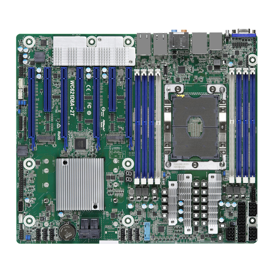
WC621D8A-2T 1.4 Motherboard Layout 26.67cm (10.5 in) DDR4_C1 (64 bit, 288-pin module), Blue PSU_SMB1 DDR4_B1 (64 bit, 288-pin module). Blue ATX12V3 ATX12V2 DDR4_A1 (64 bit, 288-pin module), Blue ATXPWR1 FRNT_VGA1 DDR4_A2 (64 bit, 288-pin module), White AEP_1 ATX12V1 CPU1 USB31_TC_2... - Page 14 Description 1 x 288-pin DDR4 DIMM Slot (DDR4_A2, White) 3 x 288-pin DDR4 DIMM Slots (DDR4_A1, DDR4_B1, DDR4_C1, Blue) Support NVDIMM Jumper (AEP_1) PSU SMBus (PSU_SMB1) ATX 12V Power Connector (ATX12V2) ATX 12V Power Connector (ATX12V3) ATX Power Connector (ATXPWR1) ATX 12V Power Connector (ATX12V1) LGA 3647 CPU Socket (CPU1) Support NVDIMM Jumper (AEP_2)
- Page 15 WC621D8A-2T Description CPU PECI Jumper (PECI1) Chassis ID2 Jumper (CHASSIS_ID2) Chassis ID0 Jumper (CHASSIS_ID0) Chassis ID1 Jumper (CHASSIS_ID1) BMC SMBus Header (BMC_SMB_1) Intelligent Platform Management Bus header (IPMB_1) COM Port Header (COM1) Front Panel Audio Header (HD_AUDIO1) Non Maskable Interrupt Button (NMI_BTN1) M.2 Socket (M2_1) (Type 2230 / 2242 / 2260 / 2280 / 22110)
-
Page 16: Onboard Led Indicators
DDR4_D2 (64 bit, 288-pin module), White DDR4_D1 (64 bit, 288-pin module), Blue DDR4_E1 (64 bit, 288-pin module), Blue FAN1 DDR4_F1 (64 bit, 288-pin module), Blue FAN2 FAN3 Intel C621 WC621D8A-2T FAN4 RoHS FAN5 FAN6 Status Description Green STB PWR ready... -
Page 17: I/O Panel
WC621D8A-2T 1.6 I/O Panel No. Description No. Description VGA Port (VGA1) Rear Speaker (Black) UID Switch (UID1) Central / Bass (Orange) USB 3.1 Gen1 Ports (USB3_1_2) Microphone (Pink) PS/2 Mouse/Keyboard Port Front Speaker (Lime)*** USB 3.1 Gen2 Port (USB31_TC_1) Line In (Light Blue) USB 3.1 Gen1 Port (USB31_TA_1) - Page 18 **There are two LEDs on each LAN port. Please refer to the table below for the LAN port LED indications. SPEED LED ACT/LINK LED LAN Port 10G LAN Port (X550_LAN1, X550_LAN2) LED Indications Speed LED Activity / Link LED Status Description Status Description...
-
Page 19: Block Diagram
WC621D8A-2T 1.7 Block Diagram ... -
Page 20: Chapter 2 Installation
Chapter 2 Installation This is an CEB form factor (12” x 10.5”, 30.5 cm x 26.67 cm) motherboard. Before you install the motherboard, study the configuration of your chassis to ensure that the motherboard fits into it. Make sure to unplug the power cord before installing or removing the motherboard. Failure to do so may cause physical injuries to you and damages to motherboard components. -
Page 21: Pre-Installation Precautions
WC621D8A-2T 2.2 Pre-installation Precautions Take note of the following precautions before you install motherboard components or change any motherboard settings. 1. Unplug the power cord from the wall socket before touching any components. 2. To avoid damaging the motherboard’s components due to static electricity, NEVER place your motherboard directly on the carpet or the like. -
Page 22: Installing The Cpu And Heatsink
2.3 Installing the CPU and Heatsink 1. Before you insert the CPU into the socket, please check if the PnP cap is on the socket, if the CPU surface is unclean, or if there are any bent pins in the socket. Do not force to insert the CPU into the socket if above situation is found. - Page 23 WC621D8A-2T 1. Before you installed the heatsink, you need to spray thermal interface material between the CPU and the heatsink to improve heat dissipation. 2. Illustration in this documentation are examples only. Heatsink or fan cooler type may differ.
- Page 25 WC621D8A-2T Tighten the two Corner Plunger to 12 IN.LB. Two turns at a time. Tighten the two Middle Nuts to 12 IN.LB. Two turns at a time.
-
Page 26: Installation Of Memory Modules (Dimm)
2.4 Installation of Memory Modules (DIMM) This motherboard provides eight 288-pin DDR4 (Double Data Rate 4) DIMM slots in two groups, and supports Six Channel Memory Technology. A single memory module should be installed in the Blue socket. CPU1 1 DIMM 2 DIMMS 4 DIMMS 8 DIMMS... - Page 27 WC621D8A-2T The DIMM only fits in one correct orientation. It will cause permanent damage to the motherboard and the DIMM if you force the DIMM into the slot at incorrect orientation.
-
Page 28: Expansion Slots (Pci Express Slots)
2.5 Expansion Slots (PCI Express Slots) There are 7 PCI Express slots on this motherboard. PCIE slot: PCIE1, PCIE3, PCIE5 and PCIE7 (PCIE 3.0 x16 slot, from CPU1) are used for PCI Express x16 lane width graphics cards. PCIE2, PCIE4 and PCIE6 (PCIE 3.0 x8 slot, from CPU1) are used for PCI Express x8 lane width graphics cards. - Page 29 WC621D8A-2T Installing an expansion card Step 1. Before installing an expansion card, please make sure that the power supply is switched off or the power cord is unplugged. Please read the documentation of the expansion card and make necessary hardware settings for the card before you start the installation.
-
Page 30: Jumper Setup
2.6 Jumper Setup The illustration shows how jumpers are setup. When the jumper cap is placed on the pins, the jumper is “Short”. If no jumper cap is placed on the pins, the jumper is “Open”. The illustration shows a 3-pin jumper whose pin1 and pin2 are “Short” when a jumper cap is placed on these 2 pins. - Page 31 WC621D8A-2T Chassis ID0 Jumper (3-pin CHASSIS_ID0) (see p.7, No. 36) Chassis ID1 Jumper (3-pin CHASSIS_ID1) (see p.7, No. 37) Chassis ID2 Jumper (3-pin CHASSIS_ID2) (see p.7, No. 35) Board Level SKU (Default) Reserved for system level Chassis ID0 Jumper (3-pin CHASSIS_ID0) (see p.7, No.
-
Page 32: Onboard Headers And Connectors
2.7 Onboard Headers and Connectors Onboard headers and connectors are NOT jumpers. Do NOT place jumper caps over these headers and connectors. Placing jumper caps over the headers and connectors will cause permanent damage to the motherboard. System Panel Header C onnec t t he power sw itch, PLED+ PLED-... - Page 33 WC621D8A-2T Auxiliary Panel Header This header supports multiple (18-pin AUX PANEL1) functions on the front panel, (see p.7, No. 27) including the front panel SMB, internet status indicator and chassis intrusion pin. A. Front panel SMBus connecting pin (6-1 pin FPSMB) This header allows you to connect SMBus (System Management Bus) equipment.
- Page 34 Front Panel Type C USB There is one Front Panel Type 3.1 Gen2 Header C USB 3.1 Gen2 Header on (20-pin USB31_TC_2) this motherboard. This header (see p.7, No. 44) is used for connecting a USB 3.1 Gen2 module for additional USB 3.1 Gen2 ports.
- Page 35 WC621D8A-2T Front Panel Audio Header This is an interface for the PRESENCE# MIC_RET (9-pin HD_AUDIO1) front panel audio cable that OUT_RET (see p.7, No. 41) allows convenient connection and control of audio devices. OUT2_L J_SENSE OUT2_R MIC2_R MIC2_L 1. High Definition Audio supports Jack Sensing, but the panel wire on the chassis must support HDA to function correctly.
- Page 36 System Fan Please connect fan cables to the Connectors fan connectors and match the (6-pin FAN1) black wire to the ground pin. FAN_VOLTAGE FAN_SPEED (see p.7, No. 14) All fans support Fan Control. FAN_SPEED_CONTROL SENSOR (6-pin FAN2) (see p.7, No. 15) (6-pin FAN3) (see p.7, No.
- Page 37 WC621D8A-2T SCLOCK Serial General Purpose These headers support Serial SLOAD Input/Output Headers Li n k i nter face for onboa rd (7-pin SATA_SGPIO1) SATA connections. (see p.7, No. 29) SDATAOUT (7-pin SSATA_SGPIO1) (see p.7, No. 30) ALERT PSU SMBus PSU SMBus monitors the...
- Page 38 Virtual RAID On CPU This connector supports Intel® Header Virtual RAID on CPU and VROC RAID KEY (4-pin RAID_1) NVME/AHCI RAID on CPU (see p.7, No. 25) PCIE. +3VSB With the introduction of the Intel VROC product, there are three modes of operation: HW key required Key features • Pass-thru only (no RAID)
-
Page 39: Unit Identification Purpose Led/Switch
WC621D8A-2T 2.8 Unit Identification purpose LED/Switch With the UID button, You are able to locate the server you’re working on from behind a rack of servers. Unit Identification When the UID button on the purpose LED/Switch front or rear panel is pressed,... -
Page 40: M.2_Ssd (Ngff) Module Installation Guide
2.10 M.2_SSD (NGFF) Module Installation Guide The M.2, also known as the Next Generation Form Factor (NGFF), is a small size and versatile card edge connector that aims to replace mPCIe and mSATA. The M.2_1 Socket supports M.2 SATA3 6.0 Gb/s module and M.2 PCI Express module up to Gen3 x4 (3.94 GB/s or 31.51 Gb/s). - Page 41 WC621D8A-2T Step 3 Move the standoff based on the module type and length. The standoff is placed at the nut location E by default. Skip Step 3 and 4 and go straight to Step 5 if you are going to use the default nut.
- Page 42 Step 6 Tighten the screw with a screwdriver to secure the module into place. Please do not overtighten the screw as this might damage the module. NUT2 NUT1...
-
Page 43: Chapter 3 Uefi Setup Utility
WC621D8A-2T Chapter 3 UEFI Setup Utility 3.1 Introduction Th is section explains how to use the UEFI SETUP UTILITY to confi gure your system. Th e UEFI chip on the motherboard stores the UEFI SETUP UTILITY. You may run the UEFI SETUP UTILITY when you start up the computer. -
Page 44: Navigation Keys
3.1.2 Navigation Keys Please check the following table for the function description of each navigation key. Navigation Key(s) Function Description Moves cursor left or right to select Screens Moves cursor up or down to select items + / - To change option for the selected items <Tab>... -
Page 45: Main Screen
WC621D8A-2T 3.2 Main Screen Once you enter the UEFI SETUP UTILITY, the Main screen will appear and display the system overview. The Main screen provides system overview information and allows you to set the system time and date. -
Page 46: Oc Tweaker Screen
3.3 OC Tweaker Screen In the OC Tweaker screen, you can set up overclocking features. Because the UEFI software is constantly being updated, the following UEFI setup screens and descriptions are for reference purpose only, and they may not exactly match what you see on your screen. - Page 47 WC621D8A-2T CPU Mesh Max Ratio The sets the maximum ratio for the CPU Mesh. CPU Mesh Min Ratio The sets the minimum ratio for the CPU Mesh. Boot Performance Mode Select the performance state that the BIOS will set before OS hand off.
- Page 48 Pll Trim for Memory Controller Change PLL Trim value for memory controller between +63 to -63. Pll Trim Prefix for Memory Controller Change PLL Trim prefix for memory controller. CPU Tj Max Set CPU Tj Max to adjust TCC Target Temperature. Default is 105 AVX2 Negative Offset AVX2 Negative Offset applied by Pcode OC mailbox read(0x1A)/Write(0x1B).
- Page 49 WC621D8A-2T DRAM Configuration Enforce POR Enable to enforce POR restrictions for DDR4 frequency and voltage programming. IMC BCLK If [Auto] is selected, it will be 100MHz or 133MHz. Primary Timing The time between sending a column address to the memory and the beginning of the data in response.
- Page 50 the same rank. tRRD The number of clocks between two rows activated in different banks of the same rank. tRRD_L The number of clocks between two rows activated in different banks of the same rank. tRTP The number of clocks that are inserted between a read command to a row pre- charge command to the same rank.
- Page 51 WC621D8A-2T tCCD Configure back to back CAS to CAS (i.e. READ to RAED or WRITE to WRITE) from same rank separation parameter. tCCD_L Configure back to back CAS to CAS (i.e. READ to RAED or WRITE to WRITE) from same rank separation parameter.
- Page 52 parameter. tRWDD Configure Back to back READ to WRITE from different dimm separation param- eter. tWRDS Back to back WRITE to READ from different subranks within the same logical rank separation parameter for LRDIMM. Min: 1 Max: 31 tWRDR Back to back WRITE to READ from different RANK separation parameter. tWRDD Configure Write to Read different DIMM dead cycle Back to back READ to WRITE from different DIMM separation parameter.
- Page 53 WC621D8A-2T RTL_A2 Configure round trip latency. RTL_B1 Configure round trip latency. RTL_C1 Configure round trip latency. RTL_D1 Configure round trip latency. RTL_D2 Configure round trip latency.\ RTL_E1 Configure round trip latency. RTL_F1 Configure round trip latency. IO-L_A1 Configure IO latency.
- Page 54 IO-L_D2 Configure IO latency. IO-L_E1 Configure IO latency. IO-L_F1 Configure IO latency. Advanced Setting ODT WR (A1) Configure the memory on die termination resistors' WR for A1. ODT WR (A2) Configure the memory on die termination resistors' WR for A2. ODT WR (B1) Configure the memory on die termination resistors' WR for B1.
- Page 55 WC621D8A-2T ODT PARK (A2) Configure the memory on die termination resistors' PARK for B2. ODT PARK (B1) Configure the memory on die termination resistors' PARK for B1. ODT PARK (C1) Configure the memory on die termination resistors' PARK for C1.
- Page 56 ODT NOM (D1) Use this to change ODT (D1) Auto/Manual settings. The default is [Auto]. ODT NOM (E1) Use this to change ODT (E1) Auto/Manual settings. The default is [Auto]. ODT NOM (F1) Use this to change ODT (F1) Auto/Manual settings. The default is [Auto]. C/A Parity Enable [Enable] - Enables DDR4 Command Address Parity.
- Page 57 WC621D8A-2T Attempt Fast Boot [Enable] - Protions of memory reference code will be skipped when possible to increase boot speed on warm boots. [Disable] - Disable this feature. [Audo] - Sets it to the MRC default setting; current default is Disable.
- Page 58 VPPM ABC Mode Use this item to select VPPM ABC mode. Options: auto / fixed mode / offset mode. VDDQ DEF Mode Use this item to select VDDQ DEF mode. Options: auto / fixed mode / offset mode. VPPM DEF Mode Use this item to select VPPM DEF mode.
- Page 59 WC621D8A-2T CPU Mesh Voltage Offset Configure the voltage for the CPU Mesh Voltage Offset(V). Min = -1.000V Max = 1.000V Offset Prefix Sets the offset value as positive or negative. System Agent Voltage Offset Configure the amount of voltage fed to the System Agent of the processor including its PCIe controller and Power control Unit (PCU).
-
Page 60: Advanced Screen
3.4 Advanced Screen In this section, you may set the configurations for the following items: CPU Configuration, DRAM Configuration, Chipset Configuration, Storage Configuration, ACPI Configura- tion, USB Configuration, Super IO Configuration, Serial Port Console Redirection, H/W Monitor, Runtime Error Logging, Intel ME Configuration, Intel® VMD technology and Instant Flash. -
Page 61: Cpu Configuration
WC621D8A-2T 3.4.1 CPU Configuration Intel Hyper Threading Technology Intel Hyper Threading Technology allows multiple threads to run on each core, so that the overall performance on threaded software is improved. Active Processor 1 Cores Select the number of cores to enable in each processor package. - Page 62 DCU Streamer Prefetcher DCU streamer prefetcher is an L1 data cache prefetcher (MSR 1A4h [2]). Hardware Prefetcher Automatically prefetch data and code for the processor. Enable for better performance. Adjacent Cache Line Prefetch Automatically prefetch the subsequent cache line while retrieving the currently requested cache line.
-
Page 63: Dram Configuration
WC621D8A-2T 3.4.2 DRAM Configuration Numa Use this item to enable or disable Non Uniform Memory Access (NUMA). Channel Interleaving Select to configure Channel Interleaving settings. Rank Interleaving Select to configure Rank Interleaving settings. Mirror Mode Mirror Mode will set entire 1LM/2LM memory in system to be mirrored, consequently reducing the memory capacity by half. - Page 64 Patrol Scrub Patrol Scrub is a background activity initiated by the processor to seek out and fix memory errors. The default value is [Enabled]. Data Scrambling for DDR4 Enable - Enables data scrambling for DDR4. Disable - Disables this feature. Auto - Sets it to the MRC default setting;...
-
Page 65: Chipset Configuration
WC621D8A-2T 3.4.3 Chipset Configuration MMCFG Base Use this item to select MMCFG Base. MMIO High Base Use this item to select MMIO High Base. MMIO High Size Use this item to select MMIO High Size. Above 4G Decoding Enable or disable 64bit capable Devices to be decoded in Above 4G Address Space (only if the system supports 64 bit PCI decoding). - Page 66 Onboard LAN This allows you to enable or disable the Onboard LAN feature. VT-d Intel Virtualization Technology for Directed I/O helps your virtual machine monitor bet- ter utilize hardware by improving application compatibility and reliability, and providing additional levels of manageability, security, isolation, and I/O performance. PCIE Hot Plug Use this item to enable or disable PCIe Hot Plug globally.
- Page 67 WC621D8A-2T Onboard Debug Port LED Enable/Disable the onboard Dr. Debug LED. PS2 Y-Cable Enable the PS2 Y-Cable or set this option to Auto. Restore on AC/Power Loss Select the power state after a power failure. If [Power Off] is selected, the power will remain off when the power recovers.
-
Page 68: Storage Configuration
3.4.4 Storage Configuration Hard Disk S.M.A.R.T. Use this item to enable or disable the S.M.A.R.T. (Self-Monitoring, Analysis, and Reporting Technology) feature. Configuration options: [Disabled] and [Enabled]. SATA Storage Configuration SATA Controller Use this item to enable or disable SATA Controllers. SATA Mode Selection Identify the SATA/M.2_SATA port is connected to Solid State Drive or Hard Disk Drive. - Page 69 WC621D8A-2T sSATA Mode Selection Identify the sSATA port is connected to Solid State Drive or Hard Disk Drive. Press <Ctrl+I> to enter RAID ROM during UEFI POST process. sSATA ALPM Use this item to enable or disable SALP.
-
Page 70: Acpi Configuration
3.4.5 ACPI Configuration Suspend to RAM Select disable for ACPI suspend type S1. It is recommended to select auto for ACPI S3 power saving. PS/2 Keyboard Power On Allow the system to be waked up by a PS/2 Keyboard. PCIE Devices Power On Use this item to enable or disable PCIE devices to turn on the system from the power-soft- off mode. - Page 71 WC621D8A-2T USB Mouse Power On Allow the system to be waked up by an USB mouse.
-
Page 72: Usb Configuration
3.4.6 USB Configuration Legacy USB Support Use this option to enable or disable legacy support for USB devices. The default value is [Enabled]. -
Page 73: Super Io Configuration
WC621D8A-2T 3.4.7 Super IO Configuration Serial Port 1 Configuration Use this item to set parameters of Serial Port 1 (COM1). Serial Port Use this item to enable or disable the serial port. Change Settings Use this item to select an optimal setting for Super IO device. -
Page 74: Serial Port Console Redirection
3.4.8 Serial Port Console Redirection COM1 / SOL Console Redirection Use this option to enable or disable Console Redirection. If this item is set to Enabled, you can select a COM Port to be used for Console Redirection. Console Redirection Settings Use this option to configure Console Redirection Settings, and specify how your computer and the host computer to which you are connected exchange information. - Page 75 WC621D8A-2T Bits Per Second Use this item to select the serial port transmission speed. The speed used in the host computer and the client computer must be the same. Long or noisy lines may require lower transmission speed. The options include [9600], [19200], [38400], [57600] and [115200].
- Page 76 Serial Port for Out-of-Band Management/Windows Emergency Management Services (EMS) Console Redirection Use this option to enable or disable Console Redirection. If this item is set to Enabled, you can select a COM Port to be used for Console Redirection. Console Redirection Settings Use this option to configure Console Redirection Settings, and specify how your computer and the host computer to which you are connected exchange information.
-
Page 77: H/W Monitor
WC621D8A-2T 3.4.9 H/W Monitor In this section, it allows you to monitor the status of the hardware on your system, includ- ing the parameters of the CPU temperature, motherboard temperature, CPU fan speed, chassis fan speed, and the critical voltage. - Page 78 FAN6 This allows you to set the fan6’s speed. The default value is [Smart Fan]. Smart Fan Control This allows you to set the Smart fan’s level speed. Smart Fan Duty Control Smart Fan Duty x (x means 1 to 11 stage) This allows you to set duty cycle for each stage.
-
Page 79: Runtime Error Logging
WC621D8A-2T 3.4.10 Runtime Error Logging WHEA Support Use this item to enable or disable Windows Hardware Error Architecture. System Error Use this item to enable or disable System Error feature. When it is set to [Enabled], you can configure Memory Error and PCIE Error log features. - Page 80 PCIE Uncorrected Error Enable Use this item to enable or disable PCIe Uncorrectable errors. PCIE Fatal Error Enable Use this item to enable or disable PCIe Ftal errors.
-
Page 81: Intel Me Configuration
WC621D8A-2T 3.4.11 Intel ME Configuration ME Subsystem screen displays the Intel ME Subsystem Configuration information, such as Operational Firmware Version and Firmware State. -
Page 82: Intel® Vmd Technology
3.4.12 Intel® VMD technology Press <Enter> to bring up the Intel(R) VMD for Volume Management Device Configuration menu. Intel(R) VMD for Volume Management Device on Socket 1 Intel(R) VMD for Volume Management Device Technology Use this item to enable or disable Intel(R) Volume Management Device Technology in this Stack. - Page 83 WC621D8A-2T Hot Plug Capable Enable/Disable Hot Plug for PCIe Root Ports 1A-1D. Intel(R) VMD for Volume Management Device Technology Use this item to enable or disable Intel(R) Volume Management Device Technology in this Stack. When [Enabled], users are allowed to configure the options below.
- Page 84 VMD port 3C Use this item to enable or disable Intel(R) Volume Management Device Technology on specific root port. VMD port 3D Use this item to enable or disable Intel(R) Volume Management Device Technology on specific root port. Hot Plug Capable Use this item to enable or disable Hot Plug for PCIe Root Ports 3A-3D.
-
Page 85: Instant Flash
WC621D8A-2T 3.4.13 Instant Flash Instant Flash is a UEFI flash utility embedded in Flash ROM. This convenient UEFI update tool allows you to update system UEFI without entering operating systems ® first like MS-DOS or Windows . Just save the new UEFI file to your USB flash drive,... -
Page 86: Security
3.5 Security In this section, you may set or change the supervisor/user password for the system. For the user password, you may also clear it. Supervisor Password Set or change the password for the administrator account. Only the administrator has authority to change the settings in the UEFI Setup Utility. Leave it blank and press enter to remove the password. -
Page 87: Key Management
WC621D8A-2T 3.5.1 Key Management In this section, expert users can modify Secure Boot Policy variables without full authenti- cation. Provision Factory Defaults Allow to provision factory default Secure Boot keys when System is in Setup Mode. Install Default Secure Boot Keys Please install default secure boot keys if it’s the first time you use secure boot. - Page 88 d) EFI_CERT_SHA256, 384, 512 2. Authenticated UEFI Variable 3. EFI PE/COFF Image(SHA256) Key Source: Default, External, Mixed, Test Key Exchange Keys Enroll Factory Defaults or load certificates from a file: 1. Public Key Certificate in: a) EFI_SIGNATURE_LIST b) EFI_CERT_X509 (DER encoded) c) EFI_CERT_RSA2048 (bin) d) EFI_CERT_SHA256, 384, 512 2.
- Page 89 WC621D8A-2T a) EFI_SIGNATURE_LIST b) EFI_CERT_X509 (DER encoded) c) EFI_CERT_RSA2048 (bin) d) EFI_CERT_SHA256, 384, 512 2. Authenticated UEFI Variable 3. EFI PE/COFF Image(SHA256) Key Source: Default, External, Mixed, Test Authorized TimeStamps Enroll Factory Defaults or load certificates from a file: 1. Public Key Certificate in:...
-
Page 90: Boot Screen
3.6 Boot Screen In this section, it will display the available devices on your system for you to configure the boot settings and the boot priority. Boot Option #1 Use this item to set the system boot order. Boot Option Filter This option controls Legacy/UEFI ROMs priority. - Page 91 WC621D8A-2T Full Screen Logo Use this item to enable or disable OEM Logo. The default value is [Enabled]. AddOn ROM Display Use this option to adjust AddOn ROM Display. If you enable the option “Full Screen Logo” but you want to see the AddOn ROM information when the system boots, please select [Enabled].
-
Page 92: Csm Parameters
3.6.1 CSM Parameters Enable to launch the Compatibility Support Module. Please do not disable unless you’re running a WHCK test. If you are using Windows 10 64-bit and all of your devices support UEFI, you may also disable CSM for faster boot speed. Launch Other Storage OpROM Policy Select UEFI only to run those that support UEFI option ROM only. - Page 93 WC621D8A-2T PCIE5/PCIE4 Slot OpROM This option controls Legacy/UEFI ROMs priority. PCIE7/PCIE6 Slot OpROM This option controls Legacy/UEFI ROMs priority. PCIE M.2_1 Slot OpROM This option controls Legacy/UEFI ROMs priority. PCIE M.2_2 Slot OpROM This option controls Legacy/UEFI ROMs priority.
-
Page 94: Event Logs
3.7 Event Logs Change Smbios Event Log Settings This allows you to configure the Smbios Event Log Settings. When entering the item, you will see the followings: Smbios Event Log Use this item to enable or disable all features of the SMBIOS Event Logging during system boot. -
Page 95: Server Mgmt
WC621D8A-2T 3.8 Server Mgmt Wait For BMC Wait For BMC response for specified time out. In PILOTII, BMC starts at the same time when BIOS starts during AC power ON. It takes around 30 seconds to initialize Host to BMC interfaces. -
Page 96: System Event Log
3.8.1 System Event Log SEL Components Change this to enable ro disable all features of System Event Logging during boot. Erase SEL Use this to choose options for earsing SEL. When SEL is Full Use this to choose options for reactions to a full SEL. Log EFI Status Codes Use this item to disable the logging of EFI Status Codes or log only error code or only progress or both. -
Page 97: Bmc Network Configuration
WC621D8A-2T 3.8.2 BMC Network Configuration BMC Out of Band Access Enabled/Disabled BMC Out of band Access. Lan Channel (Failover) Manual Setting IPMI LAN If [No] is selected, the IP address is assigned by DHCP. If you prefer using a static IP address, toggle to [Yes], and the changes take effect after the system reboots. - Page 98 The default login information for the IPMI web interface is: Username: admin Password: admin For more instructions on how to set up remote control environment and use the IPMI man- agement platform, please refer to the IPMI Configuration User Guide or go to the Support website at: http://www.asrockrack.com/support/ipmi.asp BMC Tools Load BMC Default Settings...
-
Page 99: Exit Screen
WC621D8A-2T 3.9 Exit Screen Save Changes and Exit When you select this option, the following message “Save configuration changes and exit setup?” will pop-out. Press <F10> key or select [Yes] to save the changes and exit the UEFI SETUP UTILITY. -
Page 100: Chapter 4 Software Support
4.2.4 Contact Information If you need to contact ASRock Rack or want to know more about ASRock Rack, welcome to visit ASRock Rack’s website at http://www.ASRockRack.com; or you may contact your... -
Page 101: Chapter 5 Troubleshooting
WC621D8A-2T Chapter 5 Troubleshooting 5.1 Troubleshooting Procedures Follow the procedures below to troubleshoot your system. Always unplug the power cord before adding, removing or changing any hardware com- ponents. Failure to do so may cause physical injuries to you and damages to motherboard components. - Page 102 1. Verify if the battery on the motherboard provides ~3VDC. Install a new battery if it does not. 2. Confirm whether your power supply provides adaquate and stable power. Other problems... 1. Try searching keywords related to your problem on ASRock Rack’s FAQ page: http://www.asrockrack.com/support...
-
Page 103: Technical Support Procedures
WC621D8A-2T 5.2 Technical Support Procedures If you have tried the troubleshooting procedures mentioned above and the problems are still unsolved, please contact ASRock Rack’s technical support with the following information: 1. Your contact information 2. Model name, BIOS version and problem type.
Need help?
Do you have a question about the WC621D8A-2T and is the answer not in the manual?
Questions and answers