
Related Manuals for ASROCK Rack W790D8HM3


Summary of Contents for ASROCK Rack W790D8HM3
- Page 1 W790D8HM3 User Manual Version 1.0 Published August 2023 Copyright©2023 ASRock Rack INC. All rights reserved.
- Page 2 In no event shall ASRock Rack, its directors, officers, employees, or agents be liable for any indirect, special, incidental, or consequential damages (including damages for loss of...
- Page 3 INTEL END USER SOFTWARE LICENSE AGREEMENT IMPORTANT - READ BEFORE COPYING, INSTALLING OR USING. LICENSE. Licensee has a license under Intel’s copyrights to reproduce Intel’s Software only in its unmodified and binary form, (with the accompanying documentation, the “Software”) for Licensee’s personal use only, and not commercial use, in connection with Intel-based products for which the Software has been provided, subject to the following conditions: (a) Licensee may not disclose, distribute or transfer any part of the Software, and You agree...
- Page 4 If you require assistance please call ASRock Rack Tel : +886-2-55599600 ext.123 (Standard International call charges apply) ASRock Rack’s Website: www.ASRockRack.com...
- Page 5 ASRock Rack follows the green design concept to design and manufacture our products, and makes sure that each stage of the product life cycle of ASRock Rack product is in line with global environmental regulations. In addition, ASRock Rack disclose the relevant in- formation based on regulation requirements.
-
Page 6: Table Of Contents
Contents Chapter 1 Introduction Package Contents Specifications Unique Features Motherboard Layout Onboard LED Indicators I/O Panel Block Diagram Chapter 2 Installation Screw Holes Pre-installation Precautions Installing the CPU and Heatsink Installation of Memory Modules (DIMM) Expansion Slots (PCI Express Slots) Jumper Setup Onboard Headers and Connectors Unit Identification purpose LED/Switch... - Page 7 3.2.1 Motherboard Information 3.2.2 Processor Information 3.2.3 Memory Information OC Tweaker 3.3.1 CPU Configuration 3.3.2 DRAM Configuration 3.3.3 Voltage Configuration 3.3.4 FIVR Configuration Advanced Screen 3.4.1 CPU Configuration 3.4.2 Platform Power Configuration 3.4.3 Chipset Configuration 3.4.4 PCH-FW Configuration 3.4.5 Storage Configuration 3.4.6 NVMe Configuration 3.4.7 ACPI Configuration 3.4.8 USB Configuration...
- Page 8 3.4.16 Driver Health 3.4.17 All CPU Informaton 3.4.18 Emulation Configuration 3.4.19 Tls Auth Configuration 3.4.20 MEBx 3.4.21 Instant Flash Security 3.5.1 Key Management Event Logs Boot Screen 3.7.1 CSM Parameters Server Mgmt 3.8.1 BMC Network Configuration 3.8.2 System Event Log 3.8.3 BMC Tools Exit Screen Chapter 4 Software Support...
-
Page 9: Chapter 1 Introduction
In case any modifications of this manual occur, the updated version will be available on ASRock Rack website without further notice. You may find the latest memory and CPU support lists on ASRock Rack website as well. ASRock Rack’s Website: www.ASRockRack.com About this motherboard technical support, please visit the website for specific informa- tionhttp://www.asrockrack.com/support/... -
Page 10: Specifications
1.2 Specifications W790D8HM3 Physical Status Form Factor Half-Width Dimension 6.6” x 17” (167.64 x 431.8mm) Processor System Supports Intel® Xeon® W-2400 and W-3400 series processors Socket Single Socket E (LGA 4677) Thermal Design ~350W Power (TDP) Support O.C. ~600W Chipset Intel®... - Page 11 Type AMI 256Mb SPI Flash ROM Features Plug and Play, ACPI 5.0 and above compliance wake up events, SMBIOS 2.3 and above, ASRock Rack Instant Flash Internal Connectors/Headers PSU Connector 4 (8-pin, Micro-Hi 12V), 1 (19-pin, CM Board Standby Power...
- Page 12 SMbus Header PMbus Header IPMB Header Clear CMOS 1 (contact pads) LED Indicators Standby Power 1 (5VSB) Fan Fail LED BMC Heartbeat Supported OS Microsoft® Windows® - Windows 10 (64 bit) - Windows 11 (64 bit) Linux® - RedHat Enterprise Linux Server 9.3 (64bit) - SUSE SLE 15.5 (64 bit) - UBuntu 23.04 (64 bit) *Please refer to the website for the latest OS support list.
-
Page 13: Unique Features
. With this utility, press the <F6> key during the POST or the <F2> key to enter into the BIOS setup menu to access ASRock Rack Instant Flash. Just launch this tool and save the new BIOS file to the USB flash drive, floppy disk or hard drive, then update the BIOS only in a few clicks without preparing an additional floppy diskette or other complicated flash utility. -
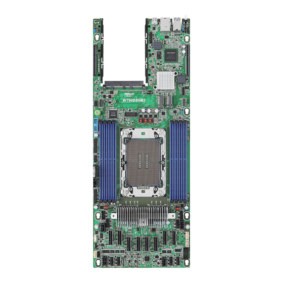
Page 14: Motherboard Layout
1.4 Motherboard Layout 16.8cm (6.6in) 8.1cm (3.2in) IPMI_LAN1 USB 3.2 Gen1 B: USB1 ASPEED AST2600 BIOS Intel® W790 OCP1 FLASH_SEC_ OVERRIDE1 W790D8HM3 CPU1... - Page 15 W790D8HM3 Description Non Maskable Interrupt Button (NMI_BTN1) Front VGA Header (FRNT_VGA1) PCI Express 5.0 x16 Slot (PCIE2) SPI TPM Header (TPM_BIOS_PH1) M-key M.2 Socket (M2_2) (Type 22110) OCuLink Connector (PCIe4.0 x4 or 4 SATA 6Gb/s) (OCU2) Security Override Jumper (SEC_OR1) M-key M.2 Socket (M2_1) (Type 2280)
- Page 16 Description Virtual RAID On CPU Header (RAID_1) Mini Cool Edge IO x8 Connector (MCIO1) Micro-Hi Power Connector (12VCON2) System Fan Connector (FAN4) System Fan Connector (FAN3) 2 x 288-pin DDR5 DIMM Slots (DDR5_E1, DDR5_G1)* 2 x 288-pin DDR5 DIMM Slots (DDR5_F1, DDR5_H1)* CM Board Standby Power Header (CM_SB_R) PSU SMBus Header (PSU_SMB1) System Panel Header (PANEL1)
-
Page 17: Onboard Led Indicators
W790D8HM3 1.5 Onboard LED Indicators... - Page 18 Item Status Description BMC_LED1 Green BMC heartbeat LED LED_CATERR2 CPU CATERR error LED_FAN1 FAN1 failed LED_FAN2 FAN2 failed LED_FAN5 FAN5 failed LED_FAN6 FAN6 failed LED_FAN4 FAN4 failed LED_FAN7 FAN7 failed LED_FAN8 FAN8 failed LED_FAN3 FAN3 failed SB_PWR1 Green STB PWR ready...
-
Page 19: I/O Panel
W790D8HM3 1.6 I/O Panel No. Description No. Description UID Switch (UID1) LAN RJ-45 Port (IPMI_LAN1)* USB 3.2 Gen1 Ports (USB3_1_2) Mini Display Port (VGA1) LAN Port LED Indications *There is an LED on each side of IPMI LAN port. Please refer to the table below for the LAN port LED indications. -
Page 20: Block Diagram
1.7 Block Diagram... -
Page 21: Chapter 2 Installation
W790D8HM3 Chapter 2 Installation This is a Ha lf-Widt h form factor (6.6” x 17”) mot herboard. Before insta lling t he motherboard, study the configuration of the chassis to ensure that the motherboard fits into it. Make sure to unplug the power cord before installing or removing the motherboard. Failure to do so may cause physical injuries and motherboard damages. -
Page 22: Installing The Cpu And Heatsink
2.3 Installing the CPU and Heatsink Socket Dust Cover CPU Carrier... - Page 23 W790D8HM3...
- Page 25 W790D8HM3 CPU Carrier...
- Page 26 Heatsink CPU Carrier Socket...
- Page 27 W790D8HM3...
-
Page 28: Installation Of Memory Modules (Dimm)
2.4 Installation of Memory Modules (DIMM) This motherboard provides eight 288-pin DDR5 (Double Data Rate 5) DIMM slots in two groups, and supports Eight Channel Memory Technology. CPU1 DDR5_A1, B1, C1, D1 DDR5_E1, F1, G1, H1 1. For Eight channel configuration, it always needs to install identical (the same brand, speed, size and chip-type) DDR5 DIMM groups. - Page 29 W790D8HM3...
-
Page 30: Expansion Slots (Pci Express Slots)
2.5 Expansion Slots (PCI Express Slots) There are 2 PCI Express slots on this motherboard. PCIE slots: PCIE1 (PCIE 5.0 x16 slot, from CPU1) is used for PCI Express x16 lane width cards. PCIE2 (PCIE 5.0 x16 slot, from CPU1) is used for PCI Express x16 lane width cards. Slot Generation Mechanical... -
Page 31: Jumper Setup
W790D8HM3 2.6 Jumper Setup The illustration shows how jumpers are setup. When the jumper cap is placed on the pins, the jumper is “Short”. If no jumper cap is placed on the pins, the jumper is “Open”. The illustration shows a 3-pin jumper whose pin1 and pin2 are “Short” when a jumper cap is placed on these 2 pins. -
Page 32: Onboard Headers And Connectors
2.7 Onboard Headers and Connectors Onboard headers and connectors are NOT jumpers. Do NOT place jumper caps over these headers and connectors. Placing jumper caps over the headers and connectors will cause permanent damage to the motherboard. System Panel Header Connect the power switch, HDLED+ PLED+... - Page 33 W790D8HM3 Auxiliary Panel Header This header supports multiple (18-pin AUX_PANEL1) functions on the front panel, (see p.6, No. 44) including the front panel SMB, internet status indicator and chassis intrusion pin. A. Front panel SMBus connecting pin (6-1 pin FPSMB) This header allows you to connect SMBus (System Management Bus) equipment.
- Page 34 CM Board Standby Power Connect this 19-pin header +12VSB Headers to the PSU for +12VSB and +12VSB (19-pin CM_SB_R) PSON PWROK. +12VSB (see p.6, No. 41) RSVD RSVD PSU_FAN_FAIL_N BMC_THROTTLE NODE_ID_1 PSON# NODE_ID_2 SMB_DATA PSU_PG SMB_CLK SMB_ALT SRST# PWM Configuration The header is used for PWM Header configurations.
- Page 35 W790D8HM3 BMC SMB Header The header is used for the SM DATA (5-pin BMC_SMB1) BUS devices. (see p.6, No. 16) +3VSB +3VSB PH Clear CMOS Pad This allows user to clear (CLRMOS1) the data in CMOS. To clear (see p.6, No. 51)
- Page 36 System Fan Connectors Please connect fan cables to (6-pin FAN1) the fan connectors and match TACH2 (see p.6, No. 12) the black wire to the ground TACH1 (6-pin FAN2) pin. All fans support Fan +12V (see p.6, No. 14) Control. (6-pin FAN5) (see p.6, No.
- Page 37 W790D8HM3 Micro-Hi Power This motherboard provides Connectors three 8-pin Micro-Hi 12V (8-pin 12VCON1) power connectors. (see p.6, No. 13) (8-pin 12VCON2) (see p.6, No. 36) (8-pin 12VCON3) (see p.6, No. 31) (8-pin 12VCON4) (see p.6, No. 22) Virtual RAID On CPU This connector supports Intel®...
- Page 38 Thermal Sensor Header Please connect the thermal (3-pin TR1) sensor cable to either pin 1-2 (see p.6, No. 49) or pin 2-3 and the other end to the device which you wish to monitor its temperature. Mini Cool Edge IO x8 This motherboard supports Connectors eight Mini Cool Edge IO x8...
- Page 39 W790D8HM3 MCIO1 Pin Definition Defeinition Pin Defeinition RX_DP0 TX_DP0 RX_DN0 TX_DN0 RX_DP1 TX_DP1 RX_DN1 TX_DN1 SPARE_A8 SCL1 WAKE# SDA1 PERST0_N PRSNT0_N RX_DP2 TX_DP2 RX_DN2 TX_DN2 RX_DP3 TX_DP3 RX_DN3 TX_DN3 RX_DP4 TX_DP4 RX_DN4 TX_DN4 RX_DP5 TX_DP5 RX_DN5 TX_DN5 SPARE_A26 SCL2 WAKE#...
- Page 40 MCIO2 Pin Definition Defeinition Pin Defeinition RX_DP8 TX_DP8 RX_DN8 TX_DN8 RX_DP9 TX_DP9 RX_DN9 TX_DN9 SPARE_A8 SCL1 WAKE# SDA1 PERST0_N PRSNT0_N RX_DP10 TX_DP10 RX_DN10 TX_DN10 RX_DP11 TX_DP11 RX_DN11 TX_DN11 RX_DP12 TX_DP12 RX_DN12 TX_DN12 RX_DP13 TX_DP13 RX_DN13 TX_DN13 SPARE_A26 SCL2 WAKE# SDA2 PERST1_N PRSNT1_N RX_DP14...
- Page 41 W790D8HM3 MCIO3 Pin Definition Defeinition Pin Defeinition RX_DP0 TX_DP0 RX_DN0 TX_DN0 RX_DP1 TX_DP1 RX_DN1 TX_DN1 SPARE_A8 SCL1 WAKE# SDA1 PERST0_N PRSNT0_N RX_DP2 TX_DP2 RX_DN2 TX_DN2 RX_DN3 TX_DP3 RX_DP3 TX_DN3 RX_DN4 TX_DP4 RX_DP4 TX_DN4 RX_DP5 TX_DP5 RX_DN5 TX_DN5 SPARE_A26 SCL2 WAKE#...
- Page 42 MCIO4 Pin Definition Defeinition Pin Defeinition RX_DN8 TX_DN8 RX_DP8 TX_DP8 RX_DP9 TX_DP9 RX_DN9 TX_DN9 SPARE_A8 SCL1 WAKE# SDA1 PERST0_N PRSNT0_N RX_DN10 TX_DN10 RX_DP10 TX_DP10 RX_DN11 TX_DP11 RX_DP11 TX_DN11 RX_DP12 TX_DP12 RX_DN12 TX_DN12 RX_DP13 TX_DN13 RX_DN13 TX_DP13 SPARE_A26 SCL2 WAKE# SDA2 PERST1_N PRSNT1_N RX_DN14...
- Page 43 W790D8HM3 MCIO5 Pin Definition Defeinition Pin Defeinition RX_DP0 TX_DP0 RX_DN0 TX_DN0 RX_DP1 TX_DP1 RX_DN1 TX_DN1 SPARE_A8 SCL1 WAKE# SDA1 PERST0_N PRSNT0_N RX_DP2 TX_DP2 RX_DN2 TX_DN2 RX_DN3 TX_DP3 RX_DP3 TX_DN3 RX_DP4 TX_DP4 RX_DN4 TX_DN4 RX_DN5 TX_DP5 RX_DP5 TX_DN5 SPARE_A26 SCL2 WAKE#...
- Page 44 MCIO6 Pin Definition Defeinition Pin Defeinition RX_DP8 TX_DP8 RX_DN8 TX_DN8 RX_DP9 TX_DP9 RX_DN9 TX_DN9 SPARE_A8 SCL1 WAKE# SDA1 PERST0_N PRSNT0_N RX_DN10 TX_DN10 RX_DP10 TX_DP10 RX_DP11 TX_DP11 RX_DN11 TX_DN11 RX_DP12 TX_DP12 RX_DN12 TX_DN12 RX_DP13 TX_DP13 RX_DN13 TX_DN13 SPARE_A26 SCL2 WAKE# SDA2 PERST1_N PRSNT1_N RX_DP14...
- Page 45 W790D8HM3 MCIO7 Pin Definition Defeinition Pin Defeinition RX_DP0 TX_DP0 RX_DN0 TX_DN0 RX_DP1 TX_DP1 RX_DN1 TX_DN1 SPARE_A8 SCL1 WAKE# SDA1 PERST0_N PRSNT0_N RX_DP2 TX_DP2 RX_DN2 TX_DN2 RX_DP3 TX_DP3 RX_DN3 TX_DN3 RX_DN4 TX_DP4 RX_DP4 TX_DN4 RX_DP5 TX_DP5 RX_DN5 TX_DN5 SPARE_A26 SCL2 WAKE#...
- Page 46 MCIO8 Pin Definition Defeinition Pin Defeinition RX_DP8 TX_DP8 RX_DN8 TX_DN8 RX_DP9 TX_DP9 RX_DN9 TX_DN9 SPARE_A8 SCL1 WAKE# SDA1 PERST0_N PRSNT0_N RX_DP10 TX_DP10 RX_DN10 TX_DN10 RX_DP11 TX_DP11 RX_DN11 TX_DN11 RX_DN12 TX_DP12 RX_DP12 TX_DN12 RX_DP13 TX_DP13 RX_DN13 TX_DN13 SPARE_A26 SCL2 WAKE# SDA2 PERST1_N PRSNT1_N RX_DP14...
-
Page 47: Unit Identification Purpose Led/Switch
W790D8HM3 2.8 Unit Identification purpose LED/Switch With the UID button, user can be able to locate the server working on from behind a rack of servers. Unit Identification When the UID button on the purpose LED/Switch front or rear panel is pressed,... -
Page 48: Ssd Module Installation Guide
2.9 M.2 SSD Module Installation Guide The M.2 Socket (M2_1/M2_2, Key M) supports either a M.2 SATA3 6.0Gb/s module or a M.2 PCI Express moduel up to Gen4x4 (16Gb/s x4). Installing the M.2 SSD Module Step 1 Prepare a M.2 SSD module and the screw. - Page 49 W790D8HM3 Step 3 Move the standoff based on the module type and length. Skip Step 3 and 4 and go straight to Step 5 if using the default nut. Otherwise, release the standoff by hand. Step 4 Peel off the yellow protective film on the nut to be used.
-
Page 50: Chapter 3 Uefi Setup Utility
Chapter 3 UEFI Setup Utility 3.1 Introduction This section explains how to use the UEFI SETUP UTILITY to configure the system. The UEFI chip on the motherboard stores the UEFI SETUP UTILITY. Run the UEFI SETUP UTILITY when starting up the computer. Please press <F2> or <Del> during the Power- On-Self-Test (POST) to enter the UEFI SETUP UTILITY;... -
Page 51: Navigation Keys
W790D8HM3 3.1.2 Navigation Keys Please check the following table for the function description of each navigation key. Navigation Key(s) Function Description Moves cursor left or right to select Screens Moves cursor up or down to select items + / - To change option for the selected items <Tab>... -
Page 52: Main Screen
3.2 Main Screen Entering the UEFI SETUP UTILITY, the Main screen displays the system overview. The Main screen provides system overview information and allows user to set the system time and date. -
Page 53: Motherboard Information
W790D8HM3 3.2.1 Motherboard Information Press [Enter] to view the information of the motheboard. 3.2.2 Processor Information Press [Enter] to view the information of the processor. -
Page 54: Memory Information
3.2.3 Memory Information Press [Enter] to view the information of the memory. -
Page 55: Oc Tweaker
W790D8HM3 3.3 OC Tweaker In the OC Tweaker screen allowing user to set up overclocking features. Because the UEFI software is constantly being updated, the following UEFI setup screens and descriptions are for reference purpose only, and may not exactly match what seeing on the screen. - Page 56 Load User Default Load previously saved user defaults. Save User UEFI Setup Profile to Disk This helps user to save current UEFI settings as an user profile to disk. Load User UEFI Setup Profile from Disk This helps user to load previous saved profile from the disk.
-
Page 57: Cpu Configuration
W790D8HM3 3.3.1 CPU Configuration CPU Core Ratio Configure the CPU Core Ratio, the CPU speed is determinded by the CPU Core Ratio mul- tiplied with the BCLK. Increasing the CPU Core Ratio will increase the internal CPU clock speed without affecting the clock spped of other components. - Page 58 Hardware P-States Select this item to configure the Hardware chooses a P-state basing on OS Request (Disable), OS guidance (Native Mode) or autonomously (Out of Band Mode). Intel Turbo Boost Max Technology 3.0 Select this item to enable or disable Intel Turbo Boost Max Technology 3.0 (ITBMT 3.0) support.
-
Page 59: Dram Configuration
W790D8HM3 3.3.2 DRAM Configuration Memory Information Allows users to browse the serial presence detect (SPD) and Intel extreme memory profile (XMP) for DDR modules. DRAM Timing Configuration Enforce DDR Memory Frequency POR Select this time to enable or disable the Enforces Plan of Record restrictions for DDR frequency programming. - Page 60 Row Precharge Time (tRP) The number of clock cycles required between the issuing of the precharge command and opening the next row. RAS# Active Time (tRAS) The number of clock cycles required between a bank active command and issuing the precharge command.
- Page 61 W790D8HM3 tREF Block Configure the number of H clocks to block scheduler before checking returned safe signals. DRAM CKE Minimum Pulse Width (tCKE) Configure the period of time the DDR4 initiates a minimum of one refresh command internally once it enters Self-Refresh mode.
- Page 62 tCPDED This is the tCPDED parameter, only used with DDR5. tCPED2SRX This is the minimum time in SR for RDIMMs (RCD) without clocking stop; the time from the SRE single CK CS# assertion to the SRX command to the RCD. tCSSR This is the tCSL timing parameter for UDIMMs (no RCD) and the tCSSR timing parameter for RDIMMs (RCD).
- Page 63 W790D8HM3 tRWSG Configure between Read CAS to Write CAS delay, same bank group. tRWSG needs to be greater than or equal to tRWSR. tWRSG Configure between Write CAS to Read CAS delay, same bank group. tWRSG needs to be greater than or equal to tWRSR.
- Page 64 tRWDD Configure between Read CAS to Write CAS delay, different DIMM. tWRDD Configure between Write CAS to Read CAS delay, different DIMM. tRRDS Configure between Read CAS to Read CAS delay, different SubRanks. tWWDS Configure between Write CAS to Write CAS delay, different SubRanks. tRWDS Configure between Read CAS to Write CAS delay, different SubRanks.
- Page 65 W790D8HM3 tRWSR Configure between Read CAS to Write CAS delay, same rank, different bank groups. tRWSG needs to be greater than or equal to tRWSR. tWRSR Configure between Write CAS to Read CAS delay, same rank, different bank groups. tWRSG needs to be greater than or equal to tWRSR.
- Page 66 tWRDS Configure between Write CAS to Read CAS delay, different SubRanks. ODT Setting ODT WR (A1)/(A2)/(B1)/(B2)/(C1)/(C2)/(D1)/(D2) Configure the memory on die termination resistors WR. ODT NOM Rd (A1)/(A2)/(B1)/(B2)/(C1)/(C2)/(D1)/(D2) Configure the memory on die termination resistors NOM Rd. ODT NOM Wr (A1)/(A2)/(B1)/(B2)/(C1)/(C2)/(D1)/(D2) Configure the memory on die termination resistors NOM Wr.
- Page 67 W790D8HM3 Attempt Fast Cold Boot [Enable] - Protions of memory reference code will be skipped when possible to increase boot speed on cold boots. [Disable] - Disable this feature. [Audo] - Sets it to the MRC default setting; current default is Disable.
-
Page 68: Voltage Configuration
3.3.3 Voltage Configuration Voltage Mode [OC] - Larger range voltage for overclocking. [Stable] - Smaller range voltage for stable system. CPU VCCIN Voltage Input voltage for the processor by the external voltage regulator. CPU VCCIN Load-Line Calibration Level3 CPU VCCIN Load-Line Calibration helps prevent VCCIN voltage droop when the system is under heavy loading. - Page 69 W790D8HM3 CPU VCCINFAON Voltage Input voltage for the processor by the external voltage regulator. CPU VCCINFAON Load-Line Calibration Level3 CPU VCCIN Load-Line Calibration helps prevent VCCINFAON voltage droop when the system is under heavy loading. CPU VCCINFAON Auto Phase Use this item to configure CPU VCCINFAON Auto Phase.
-
Page 70: Fivr Configuration
3.3.4 FIVR Configuration FIVR Configuration Processor Select this item to configure the Processor Bus Ratio Override and FIVR Override. VF Configuration Scope Select this item to configure both all cores VF curve or per-core VF curve. Core Voltage Mode Configure this item between Adaptive and Override Voltage modes. Extra Turbo Voltage Specifies the extra turbo voltage applied while Core is operation in turbo mode. - Page 71 W790D8HM3 Ring Voltage Offset Specifies the Offset Voltage applied to the Ring domain. This voltage is specified in millivolts. Offset Prefix Set the offset value as positive or negative. VCCCFN Voltage Override Specifies the Override Voltage aaplied to the VCCCFN domain.
- Page 72 MC PLL Voltage Offset PLL Voltage offset ranges from 0 to 15 bins, each bin is 15mV. Adding 5 or more bins will help to increase the range of this domain frequency in extreme overclocking conditions. The best bins will be different on each processor, user has to find the best bins for your own processor.
-
Page 73: Advanced Screen
W790D8HM3 3.4 Advanced Screen In this section, it allows user to configure and view the following items: CPU Con- f ig u r at ion, Plat for m Power C on f ig u r at ion, C h ipset C on f ig u r at ion, PCH-F W... -
Page 74: Cpu Configuration
3.4.1 CPU Configuration Active Processor Cores Select the number of cores to enable in each processor package. Intel Hyper Threading Technology Intel Hyper Threading Technology allows multiple threads to run on each core, so that the overall performance on threaded software is improved. Enable Intel TXT Support Enables Intel Trusted Execution Technology Configuration. - Page 75 W790D8HM3 DCU Streamer Prefetcher DCU streamer prefetcher is an L1 data cache prefetcher (MSR 1A4h [2]). Hardware Prefetcher Automatically prefetch data and code for the processor. Enable for better performance. Adjacent Cache Line Prefetch Automatically prefetch the subsequent cache line while retrieving the currently requested cache line.
-
Page 76: Platform Power Configuration
3.4.2 Platform Power Configuration Intel SpeedStep Technology Intel SpeedStep technology allows processors to switch between multiple frequencies and voltage points for better power saving and heat dissipation. CPU turbo ratio can be fixed when Intel SpeedStep Technology set Disabled and Intel Turbo Boost Technology set En- abled. - Page 77 W790D8HM3 Native Mode with No Legacy Support: Hardware autonomously chooses a P-state based on OS guidance with no legacy support. SST-CP Select this item to enable or disable the SST-CP feature. ® About SST configurations are base on the Intel related supported specifications.
- Page 78 PL1 Time Window 448.0000 Use this item to configure the period of time until the CPU ratio is lowered when the Long Duration Power Limit is exceeded. PL1 value is in seconds. The value may vary from 0 to 448. PL2 Power Limit4095.000 Use this item to configure Package Power Limit 2 (PL2) in watts.
-
Page 79: Chipset Configuration
W790D8HM3 3.4.3 Chipset Configuration Above 4G Decoding Use this item to enable or disable 64bit capable Devices to be decoded in Above 4G Address Space (only if the system supports 64 bit PCI decoding). Re-Size BAR Support If system has Resizable BAR capable PCIe Devices, this option enables or disables Resizable BAR support. - Page 80 Onboard VGA Use this to enable or disable the Onboard VGA function. Onboard LAN1-1 Use this to enable or disable the Onboard LAN function. Onboard LAN1-2 Use this to enable or disable the Onboard LAN function. OCU1 Function Select Select SATA or PCIe work in MiniSAS port. OCU2 Function Select Select SATA or PCIe work in MiniSAS port.
- Page 81 W790D8HM3 MCIO1-1/1-2/2-1/2-2/3-1/3-2/4-1/4-2/5-1/5-2/6-1/6-2/7-1/7-2/8-1/8-2 Link Speed Select Link Speed for MCIO1-1/1-2/2-1/2-2/3-1/3-2/4-1/4-2/5-1/5-2/6-1/6-2/7-1/7-2/8-1/8-2. PCIE Hot Plug Select this item to configure PCIE Hot Plug globally. OCU1/2 Hot Plug Enable or disable PCIE Hot Plug. PCIE1/2, OCP1, MCIO1-1/1-2/2-1/2-2/3-1/3-2/4-1/4-2/5-1/5-2/6-1/6-2/7-1/7-1/8- 1/8-2 Hot Plug Enable or disable PCIE and MCIO Hot Plug.
-
Page 82: Pch-Fw Configuration
3.4.4 PCH-FW Configuration Intel(R) Platform Trust Technology Use this item to configure Intel PTT funciton. Select Enabled to use Intel PTT in ME. Disable this option to use discrete TPM Module. -
Page 83: Storage Configuration
W790D8HM3 3.4.5 Storage Configuration SATA Controller (s) Select this item to enable or disable SATA Controllers. Force SATA Gen Speed Select this item to change SATA Gen Speed for port. SATA Mode Selection Select AHCI to support new features that improve performance. - Page 84 OCU1_SATA_0/1/2/3, OCU2_SATA_0/1/2/3 Select this item to configure the External SATA, Hot Plug, Spin Up Device and SATA Device Type. External SATA Enable or disable SATA safe removal notifications. Hot Plug Enable or disable Hot Plug for specified port. SATA Device Type Identify the SATA port is connected to Solid State Drive or Hard Disk Drive.
-
Page 85: Nvme Configuration
W790D8HM3 3.4.6 NVMe Configuration NVMe Configuration The NVMe Configuration displays the NVMe controller and Drive information. -
Page 86: Acpi Configuration
3.4.7 ACPI Configuration Suspend to RAM Select disable for ACPI suspend type S1. It is recommended to select auto for ACPI S3 power saving. PCIE Devices Power On Allow the system to be waked up by a PCIE device and enable wake on LAN. Ring-In Power On Use this item to enable or disable Ring-In signals to turn on the system from the power- soft-off mode. -
Page 87: Usb Configuration
W790D8HM3 3.4.8 USB Configuration USB Configuration The USB Configuration displays the USB Controllers and USB Devices informations. -
Page 88: Super Io Configuration
3.4.9 Super IO Configuration Serial Port 1 Configuration Use this item to set parameters of Serial Port 1 (COM1). Serial Port Use this item to enable or disable the serial port. Change Settings Use this item to select an optimal setting for Super IO device. SOL Configuration Use this item to set parameters of SOL. -
Page 89: Serial Port Console Redirection
W790D8HM3 3.4.10 Serial Port Console Redirection COM1 / SOL Console Redirection Use this option to enable or disable Console Redirection. If this item is set to Enabled, it allows user to select a COM Port to be used for Console Redirection. - Page 90 Bits Per Second Use this item to select the serial port transmission speed. The speed used in the host computer and the client computer must be the same. Long or noisy lines may require lower transmission speed. The options include [9600], [19200], [38400], [57600] and [115200]. Data Bits Use this item to set the data transmission size.
- Page 91 W790D8HM3 Out-of-Band Mgmt Port Microsof t Windows Emergency Management Services (EMS) allows for remote management of a Windows Server OS through a serial port. Terminal Type EMS Use this item to select the preferred terminal emulation type for out-of-band management.
-
Page 92: H/W Monitor
3.4.11 H/W Monitor This section allows user to monitor the status of the hardware on your system, including the parameters of the CPU temperature, motherboard temperature, CPU fan speed, chas- sis fan speed, and the critical voltage. -
Page 93: Runtime Error Logging
W790D8HM3 3.4.12 Runtime Error Logging System Error Use this item to enable or disable System Error feature. When it is set to [Enabled], it allows user to configure Memory Error and PCIE Error log features. WHEA Support Use this item to enable or disable Windows Hardware Error Architecture. - Page 94 PCIe Corrected Error Threshold PCIE Correctable Error Threshold (0x01-0xFF) used for sparing, tagging, and leaky bucket. PCIe Uncorrected Error Enable Use this item to enable or disable PCIe Uncorrectable errors. PCIe Fatal Error Enable Use this item to enable or disable PCIe Ftal errors.
-
Page 95: Workstation Me Configuration
W790D8HM3 3.4.13 Workstation ME Configuration Select this item to display the ME Version and ME FW State information. -
Page 96: Network Stack Configuration
3.4.14 Network Stack Configuration Network Stack Enable UEFI network stack can prevents to perform from the single-user network boots and network installation. If disabled, the host does not use the network interface. IPv4 PXE Support Enable IPv4 PXE Boot support. If disabled, IPv4 PXE Boot Option is not supported. IPv4 HTTP Support Enable IPv4 HTTP Boot support. -
Page 97: Intel® Vmd Technology
W790D8HM3 3.4.15 Intel® VMD technology Press <Enter> to bring up the Intel(R) VMD for Volume Management Device Configuration menu. Intel VMD for Volume Management Device on Socket 0 VMD Config for IOU0 PCIE2, IOU2 PCIE1, IOU3 MCIO2/MCIO1, IOU4 MCIO8/MCIO7, IOU5 MCIO4/MCIO3, IOU6 MCIO6/MCIO5 Use these items to enable or disable Intel(R) Volume Management Device Technology in specific Stack. -
Page 98: Driver Health
3.4.16 Driver Health Inter (R) Ethernet Connection I219 0.2.03 Healthy Provides Health Status for the Drivers/Controllers. Inter (R) 2.5G Ethernet Controller 0.10.04 Healthy Provides Health Status for the Drivers/Controllers. -
Page 99: All Cpu Informaton
W790D8HM3 3.4.17 All CPU Informaton Select this item to display all CPU information. -
Page 100: Emulation Configuration
3.4.18 Emulation Configuration uBIOS Generation Use this item to enable or disable uBIOS Generation. Hybrid SLE Mode Use this item to enable or disable Hybrid System Level Emulation Mode. MSR Trace for PM Use this item to enable or disable MSR Trace for Power management in uBIOS. -
Page 101: Tls Auth Configuration
W790D8HM3 3.4.19 Tls Auth Configuration Server CA Configuration Press <Enter> to configure Server CA. Enroll Cert Press <Enter> to enroll cert. Delete Cert Press <Enter> to delete cert. Client Cert Configuration Press <Enter> to configure Client Cert. -
Page 102: Mebx
3.4.20 MEBx This Formset contains forms for configuring MEBx. -
Page 103: Instant Flash
W790D8HM3 3.4.21 Instant Flash Instant Flash is a UEFI flash utility embedded in Flash ROM. This convenient UEFI update tool allows user to update system UEFI without entering operating systems first like MS- ® DOS or Windows . Just save the new UEFI file to the USB flash drive, floppy disk or hard drive and launch this tool, then update the UEFI only in a few clicks without preparing an additional floppy diskette or other complicated flash utility. -
Page 104: Security
3.5 Security In this section, set or change the supervisor/user password for the system. For the user password, can also clear it. Supervisor Password Set or change the password for the administrator account. Only the administrator has authority to change the settings in the UEFI Setup Utility. Leave it blank and press enter to remove the password. -
Page 105: Key Management
W790D8HM3 3.5.1 Key Management In this section, expert users can modify Secure Boot Policy variables without full authenti- cation. Factory Key Provision Install factory default Secure Boot keys after the platform reset and while the System is in Setup mode. - Page 106 Platform Key(PK) Enroll Factory Defaults or load certificates from a file: 1. Public Key Certificate in: a) EFI_SIGNATURE_LIST b) EFI_CERT_X509 (DER) c) EFI_CERT_RSA2048 (bin) d) EFI_CERT_SHAXXX 2. Authenticated UEFI Variable 3. EFI PE/COFF Image(SHA256) Key Source: Factory, Modified, Mixed Key Exchange Keys(KEK) Enroll Factory Defaults or load certificates from a file: 1.
- Page 107 W790D8HM3 2. Authenticated UEFI Variable 3. EFI PE/COFF Image(SHA256) Key Source: Factory, Modified, Mixed Forbidden Signatures(dbx) Enroll Factory Defaults or load certificates from a file: 1. Public Key Certificate in: a) EFI_SIGNATURE_LIST b) EFI_CERT_X509 (DER) c) EFI_CERT_RSA2048 (bin) d) EFI_CERT_SHAXXX 2.
- Page 108 b) EFI_CERT_X509 (DER) c) EFI_CERT_RSA2048 (bin) d) EFI_CERT_SHAXXX 2. Authenticated UEFI Variable 3. EFI PE/COFF Image(SHA256) Key Source: Factory, Modified, Mixed...
-
Page 109: Event Logs
W790D8HM3 3.6 Event Logs Change Smbios Event Log Settings Select this item to configure the Smbios Event Log Settings. When entering the item, the screen displays following sub-items: Smbios Event Log Use this item to enable or disable all features of the SMBIOS Event Logging during system boot. -
Page 110: Boot Screen
3.7 Boot Screen In this section, it will display the available devices on your system for you to configure the boot settings and the boot priority. FIXED BOOT ORDER Priorities Boot Option #1/#2/#3/#4/#5/#6 Use this item to set the system boot order. UEFI Application Boot Priorities Specifies the Boot Device Priority sequence from available UEFI Application. - Page 111 W790D8HM3 Boot Beep Select whether the Boot Beep should be turned on or off when the system boots up. Please note that a buzzer is needed. Full Screen Logo Use this item to enable or disable OEM Logo. The default value is [Enabled].
-
Page 112: Csm Parameters
3.7.1 CSM Parameters CSM (Compatibility Support Module) Enable to launch the Compatibility Support Module. Please do not disable unless running a WHCK test. If using Windows 8 64-bit UEFI and all of the devices support UEFI, it may also disable CSM for faster boot speed. Boot Option Filter This option controls Legacy/UEFI ROMs priority. - Page 113 W790D8HM3 Launch Video OpROM Policy Select UEFI only to run those that support UEFI option ROM only. Select Legacy only to run those that support legacy option ROM only. Select Do not launch to not execute both legacy and UEFI option ROM.
-
Page 114: Server Mgmt
3.8 Server Mgmt Wait For BMC Wait For BMC response for specified time out. BMC starts at the same time when BIOS starts during AC power ON. It takes around 90 seconds to initialize Host to BMC interfaces. FRB-2 Timer Select this item to enable or disable FRB-2 timer (POST timer) FRB-2 Timer Timeout Select this item to define the FRB-2 Time Expiration between 1 to 30 value. - Page 115 W790D8HM3 OS Wtd Timer Policy Configure how the system should respond if the OS Boot Watchdog Timer expires. If the OS Boot Watchdog Timer is disabled, this item is not available. BMC Network Configuration Select this item to configure BMC network parameters.
-
Page 116: Bmc Network Configuration
3.8.1 BMC Network Configuration Bonding Setting Select this item to enabled or disabled bonding. Please enable all lan channel first when want to enable bonding. eth0 enable Setting BMC LAN enable setting. eth1 enable Setting BMC LAN enable setting. Manual Setting IPMI LAN If [No] is selected, the IP address is assigned by DHCP. - Page 117 W790D8HM3 When [DHCP] or [Static] is selected, do NOT modify the BMC network settings on the IPMI web page. The default login information for the IPMI web interface is: Username: admin Password: admin For more instructions on how to set up remote control environment and use the IPMI man- agement platform, please refer to the IPMI Configuration User Guide or go to the Support website at: http://www.asrockrack.com/support/ipmi.asp...
-
Page 118: System Event Log
3.8.2 System Event Log SEL Components Change this to enable ro disable event logging for error/progress codes during boot. Erase SEL Use this to choose options for earsing SEL. When SEL is Full Use this to choose options for reactions to a full SEL. Log EFI Status Codes Use this item to disable the logging of EFI Status Codes or log only error code or only progress code or both. -
Page 119: Bmc Tools
W790D8HM3 3.8.3 BMC Tools KCS control Select the KSC interface state after POST end. If [Enabled] is selected, the BMC will remain KCS interface after POST stage. If [Disabled] is selected, the BMC will disable KCS interface after POST stage. -
Page 120: Exit Screen
3.9 Exit Screen Save Changes and Exit When selecting this option, the following message “Save configuration changes and exit setup?” will pop-out. Press <F10> key or select [Yes] to save the changes and exit the UEFI SETUP UTILITY. Discard Changes and Exit When selecting this option, the following message “Discard changes and exit setup?”... -
Page 121: Chapter 4 Software Support
Please download the operating system from the OS manufacturer. Please refer to the OS documentation for more instructions. * Please download the Intel® SATA Floppy Image driver from the ASRock Rack’s website (www.asrockrack.com) to the USB drive while installing OS in SATA RAID mode. -
Page 122: Chapter 5 Troubleshooting
Chapter 5 Troubleshooting 5.1 Troubleshooting Procedures Follow the procedures below to troubleshoot the system. Always unplug the power cord before adding, removing or changing any hardware components. Failure to do so may cause physical injuries and damages to motherboard components. 1. - Page 123 1. Verify if the battery on the motherboard provides ~3VDC. Install a new battery if it does not. 2. Confirm whether the power supply provides adaquate and stable power. Other problems... 1. Try searching keywords related to the related problem on ASRock Rack’s FAQ page: http://www.asrockrack.com/support...
-
Page 124: Technical Support Procedures
5.2 Technical Support Procedures If the problems are still unsolved, please contact ASRock Rack’s technical support with the following information: 1. Contact information 2. Model name, BIOS version and problem type. 3. System configuration. 4. Problem description. Contact ASRock Rack’s technical support at: http://www.asrockrack.com/support/tsd.asp... - Page 125 Contact Information Contact ASRock Rack or want to know more about ASRock Rack, it's welcome to visit ASRock Rack’s website at http://www.asrockrack.com; or contact the dealer for further information. For technical questions, please submit a support request form at https://event.
Need help?
Do you have a question about the W790D8HM3 and is the answer not in the manual?
Questions and answers