Sign In
Upload
Download
Table of Contents
Contents
Add to my manuals
Delete from my manuals
Share
URL of this page:
HTML Link:
Bookmark this page
Add
Manual will be automatically added to "My Manuals"
Print this page
×
Bookmark added
×
Added to my manuals
Manuals
Brands
ASROCK Rack Manuals
Motherboard
SPC621D8-2L2T
User manual
ASROCK Rack SPC621D8-2L2T User Manual
Hide thumbs
1
2
3
Table Of Contents
4
5
6
7
8
9
10
11
12
13
14
15
16
17
18
19
20
21
22
23
24
25
26
27
28
29
30
31
32
33
34
35
36
37
38
39
40
41
42
43
44
45
46
47
48
49
50
51
52
53
54
55
56
57
58
59
60
61
62
63
64
65
66
67
68
69
70
71
72
73
74
75
76
77
78
79
80
81
82
83
84
85
86
87
88
89
90
91
92
93
94
95
96
97
98
99
100
101
102
page
of
102
Go
/
102
Contents
Table of Contents
Troubleshooting
Bookmarks
Table of Contents
Table of Contents
Chapter 1 Introduction
Package Contents
Specifications
Unique Features
Motherboard Layout
Onboard LED Indicators
I/O Panel
Block Diagram
Chapter 2 Installation
Screw Holes
Pre-Installation Precautions
Installing the CPU and Heatsink
Installation of Memory Modules (DIMM)
Expansion Slots (PCI Express Slots)
Jumper Setup
Onboard Headers and Connectors
Unit Identification Purpose Led/Switch
Driver Installation Guide
M.2_SSD (NGFF) Module Installation Guide
Chapter 3 UEFI Setup Utility
Introduction
UEFI Menu Bar
Navigation Keys
Main Screen
Advanced Screen
CPU Configuration
DRAM Configuration
Chipset Configuration
Storage Configuration
ACPI Configuration
USB Configuration
Super IO Configuration
Serial Port Console Redirection
H/W Monitor
Runtime Error Logging
Intel SPS Configuration
Intel® VMD Technology
Tls Auth Configuration
Instant Flash
Security
Key Management
Boot Screen
CSM Parameters
Server Mgmt
System Event Log
View System Event Log
BMC Network Configuration
BMC Tools
Event Logs
Exit Screen
Chapter 4 Software Support
Install Operating System
Support CD Information
Running the Support CD
Drivers Menu
Utilities Menu
Contact Information
Chapter 5 Troubleshooting
Troubleshooting Procedures
Technical Support Procedures
Returning Merchandise for Service
Advertisement
Quick Links
1
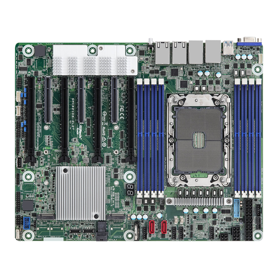
Motherboard Layout
2
Onboard Led Indicators
3
I/O Panel
4
Installing the Cpu and Heatsink
5
Installation of Memory Modules (DIMM)
6
Onboard Headers and Connectors
7
Troubleshooting Procedures
Download this manual
SPC621D8-2L2T
SPC621D8-2T
SPC621D8
User Manual
Version 1.0
Published June 2021
Copyright©2021 ASRock Rack INC. All rights reserved.
Table of
Contents
Previous
Page
Next
Page
1
2
3
4
5
Advertisement
Table of Contents
Need help?
Do you have a question about the SPC621D8-2L2T and is the answer not in the manual?
Ask a question
Questions and answers
Related Manuals for ASROCK Rack SPC621D8-2L2T
Motherboard ASROCK Rack SPC621D8-2T User Manual
(102 pages)
Motherboard ASROCK Rack SPC621D8U-2T User Manual
(94 pages)
Motherboard ASROCK Rack SP2C621D16-2T User Manual
(108 pages)
Motherboard ASROCK Rack SP2C621D16-2L+ User Manual
(108 pages)
Motherboard ASROCK Rack SPC741D8-2T/BCM User Manual
(107 pages)
Motherboard ASROCK Rack SPC741D8-2L2T/BCM Quick Installation Manual
(2 pages)
Motherboard ASROCK Rack SPC741D8M3-2T/X550 User Manual
(103 pages)
Motherboard ASROCK Rack SP2C621D32GM-2T User Manual
(105 pages)
Motherboard ASROCK Rack SP2C741D16X-2T User Manual
(106 pages)
Motherboard ASROCK Rack 2U2E-F Series User Manual
(35 pages)
Motherboard ASROCK Rack SIENAD8-2L2T User Manual
(99 pages)
Motherboard ASROCK Rack SP2C741D16NQM3-2Q User Manual
(112 pages)
Motherboard ASROCK Rack SP2C621D32TM3 User Manual
(120 pages)
Motherboard ASROCK Rack SIENAD8UD3 User Manual
Server/workstation (103 pages)
Motherboard ASROCK Rack SP2C741D32TM3 User Manual
Server workstation motherboard (123 pages)
Motherboard ASROCK Rack S4B2123 User Manual
(73 pages)
This manual is also suitable for:
Spc621d8-2t
Spc621d8
Table of Contents
Print
Rename the bookmark
Delete bookmark?
Delete from my manuals?
Login
Sign In
OR
Sign in with Facebook
Sign in with Google
Upload manual
Upload from disk
Upload from URL


Need help?
Do you have a question about the SPC621D8-2L2T and is the answer not in the manual?
Questions and answers