
Related Manuals for ASROCK Rack C236 WSI


Summary of Contents for ASROCK Rack C236 WSI
-
Page 1: User Manual
C236 WSI User Manual Version 1.0 Published November2015 Copyright©2015 ASRock Rack INC. All rights reserved. -
Page 2: Copyright Notice
In no event shall ASRock Rack, its directors, officers, employees, or agents be liable for any indirect, special, incidental, or consequential damages (including damages for loss of profits, loss of business, loss of data, interruption of business and the like), even if ASRock Rack has been advised of the possibility of such damages arising from any defect or error in the documentation or product. - Page 3 Contact Information If you need to contact ASRock Rack or want to know more about ASRock Rack, you’re welcome to visit ASRock Rack’s website at www.ASRockRack.com; or you may contact your dealer for further information. ASRock Rack Incorporation 6F., No.37, Sec. 2, Jhongyang S. Rd., Beitou District, Taipei City 112, Taiwan (R.O.C.)
-
Page 4: Table Of Contents
Contents Chapter 1 Introduction Package Contents Specifications Unique Features Motherboard Layout Onboard LED Indicators I/O Panel Block Diagram Chapter 2 Installation Screw Holes Pre-installation Precautions Installing the CPU Installing the CPU Fan and Heatsink Installation of Memory Modules (DIMM) Expansion Slot (PCI Express Slot) Onboard Headers and Connectors Driver Installation Guide Dua LAN and Teaming Operation Guide... - Page 5 Advanced Screen 3.3.1 CPU Configuration 3.3.2 Memory Configuration 3.3.3 Chipset Configuration 3.3.4 Storage Configuration 3.3.5 NVMe Configuration 3.3.6 ACPI Configuration 3.3.7 USB Configuration 3.3.8 WHEA Configuration 3.3.9 Super IO Configuration 3.3.10 Serial Port Console Redirection 3.3.11 H/W Monitor 3.3.12 Trusted Computing 3.3.13 Voltage Control 3.3.14 Instant Flash Boot Screen...
- Page 6 4.2.2 Drivers Menu 4.2.3 Utilities Menu 4.2.4 Contact Information Chapter 5 Troubleshooting Troubleshooting Procedures Technical Support Procedures Returning Merchandise for Service Chapter 6: Net Framework Installation Guide Installing .Net Framework 3.5.1 (For Server 2008 R2)
-
Page 7: Chapter 1 Introduction
In case any modifications of this manual occur, the updated version will be available on ASRock Rack website without further notice. You may find the latest memory and CPU support lists on ASRock Rack website as well. ASRock Rack’s Website: www.ASRockRack.com If you require technical support related to this motherboard, please visit our website for specific information about the model you are using. -
Page 8: Specifications
1.2 Specifications C236 WSI MB Physical Status Form Factor Mini ITX Dimension 6.7'' x 6.7'' (17.02cm x17.02 cm) Processor System Intel® Xeon® E3-1200 v5 Series Processors Chipset Intel® C236 System Memory Capacity 2 x DDR4 DIMM slots Type - Dual Channel DDR4 memory technology - Supports DDR4 2133 ECC/Non-ECC UDIMM memory Max. - Page 9 128Mb AMI UEFI Legal BIOS BIOS Features - Plug and Play (PnP) - ACPI 2.0 Compliance Wake Up Events - SMBIOS 2.8.0 Support - ASRock Rack Instant Flash Hardware Monitor Temperature - CPU Temperature Sensing - MB Temperature Sensing - System TR Temperature Sensing...
- Page 10 Support OS Microsoft® Windows® - Windows 7 (32 / 64 bit) - Windows 8.1 (64 bit) - Windows 10 (64 bit) * Please refer to our website for the latest OS support list. Environment Temperature Operation temperature: 10°C ~ 35°C / Non operation temperature: -40°C ~ 70°C NOTE: Please refer to our website for the latest specifications.
-
Page 11: Unique Features
POST or the <F2> key to enter into the BIOS setup menu to access ASRock Rack Instant Flash. Just launch this tool and save the new BIOS file to your USB flash drive, floppy disk or hard drive, then you can update your BIOS only in a few clicks without preparing an additional floppy diskette or other complicated flash utility. -
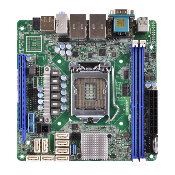
Page 12: Motherboard Layout
CMOS T 1 R Battery ATXPWR1 CPU_FAN1 FRNT_FAN1 USB 2.0 T: USB_1 B: USB_2 DDR4_B1 (64 bit, 288-pin module) DDR4_A1 (64 bit, 288-pin module) C236 WSI CLRMOS1 RoHS Intel USB 3.0 LAN1 T: USB_1 B: USB_2 C236 USB 3.0 SATA_SGPIO1... - Page 13 C236 WSI Description Thermal Sensor Header (TR1) ATX Power Connector (ATXPWR1) CPU Fan Connector (CPU_FAN1) Front Fan Connector (FRNT_FAN1) 2 x 288-pin DDR4 DIMM Slots (DDR4_A1, DDR4_B1, Blue) Clear CMOS Pad (CLRMOS1) SATA SGPIO Connector (SATA_SGPIO1) SATA SGPIO Connector (SATA_SGPIO2) Vertical Type A USB 3.0 (USB3_7)
-
Page 14: Onboard Led Indicators
1.5 Onboard LED Indicators CMOS Battery ATXPWR1 CPU_FAN1 FRNT_FAN1 USB 2.0 T: USB_1 B: USB_2 DDR4_B1 (64 bit, 288-pin module) DDR4_A1 (64 bit, 288-pin module) C236 WSI RoHS Intel USB 3.0 LAN1 T: USB_1 B: USB_2 C236 USB 3.0 SATA_SGPIO2 LAN2... -
Page 15: I/O Panel
C236 WSI 1.6 I/O Panel No. Description No. Description USB 2.0 Ports (USB_1_2) Line In (Light Blue) Serial Port (COM1) Front Speaker (Lime) VGA Port (VGA1) Microphone (Pink) LAN RJ-45 Port (LAN1)* Display Port USB 3.0 Ports (USB3_1_2) HDMI Port... -
Page 16: Block Diagram
1.7 Block Diagram 128-bit Dual-Channel Memory x 2 Slots DDR4 2133 Channel A INTEL DDR4 2133 Channel B PCI-E X16 SLOT 7 PCI-E Gen3 BUS DP Connector Processor DIGITAL PORT B 100MHz HDMI Connector DIGITAL PORT C PTN3356 Embedded DisplayPort VGA Port LGA-1151 Pin Socket USB3.0... -
Page 17: Chapter 2 Installation
C236 WSI Chapter 2 Installation This is a mini ITX form factor (6.7'' x 6.7'', 17.02 cm x 17.02 cm) motherboard. Before you install the motherboard, study the configuration of your chassis to ensure that the motherboard fits into it. -
Page 18: Installing The Cpu
2.3 Installing the CPU 1. Before you insert the 1151-Pin CPU into the socket, please check if the PnP cap is on the socket, if the CPU surface is unclean, or if there are any bent pins in the socket. Do not force to insert the CPU into the socket if above situation is found. - Page 19 C236 WSI Please save and replace the cover if the processor is removed. The cover must be placed if you wish to return the motherboard for after service.
-
Page 20: Installing The Cpu Fan And Heatsink
2.4 Installing the CPU Fan and Heatsink... -
Page 21: Installation Of Memory Modules (Dimm)
C236 WSI 2.5 Installation of Memory Modules (DIMM) This motherboard provides two 288-pin DDR4 (Double Data Rate 4) DIMM slots. 1. It is not allowed to install a DDR, DDR2 or DDR3 memory module into a DDR4 slot; otherwise, this motherboard and DIMM may be damaged. -
Page 22: Expansion Slot (Pci Express Slot)
2.6 Expansion Slot (PCI Express Slot) There is a PCI Express slot on this motherboard. PCIE slot: PCIE7 (PCIe 3.0 x16 slot) is used for PCI Express x16 lane width cards. Slot Generation Mechanical Electrical Source PCIE 7 Installing an expansion card Step 1. -
Page 23: Onboard Headers And Connectors
C236 WSI 2.7 Onboard Headers and Connectors Onboard headers and connectors are NOT jumpers. Do NOT place jumper caps over these headers and connectors. Placing jumper caps over the headers and connectors will cause permanent damage to the motherboard. System Panel Header... - Page 24 Auxiliary Panel Header This header supports multiple (18-pin AUX PANEL_1) functions on the front panel, (see p.6, No. 22) including the front panel SMB, internet status indicator and chassis intrusion pin. A. Front panel SMBus connecting pin (6-1 pin FPSMB) This header allows you to connect SMBus (System Management Bus) equipment.
- Page 25 C236 WSI Serial ATA3 Connectors These SATA3 connectors SATA_0 SATA_1 SATA_2 SATA_3 (SATA_0) support SATA data cables for (see p.6, No. 10) internal storage devices with (SATA_1) up to 6.0 Gb/s data transfer (see p.6, No. 11) rate. (SATA_2) SATA_4 (see p.6, No.
- Page 26 3-Pin CPU fan, CPU_FAN_SPEED FA N_SPEED_CONTROL please connect it to Pin 1-3. *For more details, please refer to the Cooler QVL list on the ASRock Rack website. Front Fan Connector Please connect fan cables to the (4-pin FRNT_FAN1) fan connector and match the (see p.6, No.
- Page 27 C236 WSI Serial General Purpose The headers support Serial SCLOCK SLOAD Input/Output Headers Link interface for onboard (7-pin SATA_SGPIO1) SATA connections. (see p.6, No. 7) (7-pin SATA_SGPIO2) SDATAOUT (see p.6, No. 8) Non Maskable Interrupt Please connect a NMI device Button Header to this header.
- Page 28 HDMI_SPDIF Header HDMI_SPDIF header, (2-pin HDMI_SPDIF1) providing audio output to (see p.6, No. 25) HDMI VGA card, allows the SPDIF_OUT system to connect HDMI Digital TV/ projector/LCD devices. Please connect the HDMI_SPDIF connector of HDMI VGA card to this header. Clear CMOS Pad CLRMOS1 allows you to clear (CLRMOS1)
-
Page 29: Driver Installation Guide
C236 WSI 2.8 Driver Installation Guide To install the drivers to your system, please insert the support CD to your optical drive first. Then, the drivers compatible to your system can be auto-detected and listed on the support CD driver page. Please follow the order from top to bottom to install... -
Page 30: Dua Lan And Teaming Operation Guide
2.9 Dua LAN and Teaming Operation Guide Dual LAN with Teaming enabled on this motherboard allows two single connections to act as one single connection(s) for twice the transmission bandwidth, making data transmission more effective and improving the quality of transmission of distant images. -
Page 31: Chapter 3 Uefi Setup Utility
C236 WSI Chapter 3 UEFI Setup Utility 3.1 Introduction Th is section explains how to use the UEFI SETUP UTILITY to confi gure your system. Th e UEFI chip on the motherboard stores the UEFI SETUP UTILITY. You may run the UEFI SETUP UTILITY when you start up the computer. -
Page 32: Navigation Keys
3.1.2 Navigation Keys Please check the following table for the function description of each navigation key. Navigation Key(s) Function Description Moves cursor left or right to select Screens Moves cursor up or down to select items + / - To change option for the selected items <Tab>... -
Page 33: Main Screen
C236 WSI 3.2 Main Screen Once you enter the UEFI SETUP UTILITY, the Main screen will appear and display the system overview. The Main screen provides system overview information and allows you to set the system time and date. -
Page 34: Advanced Screen
3.3 Advanced Screen In this section, you may set the configurations for the following items: CPU Configuration, Memory Configuration, Chipset Configuration, Storage Configuration, NVMe Configu- ration, ACPI Configuration, USB Configuration, WHEA Configuration, Super IO Con- figuration, Serial Port Console Redirection, H/W Monitor, Trusted Computing, Voltage Control and Instant Flash. -
Page 35: Cpu Configuration
C236 WSI 3.3.1 CPU Configuration Spread Spectrum Use this to enable and disable Spread Spectrum. Intel Hyper Threading Technology Intel Hyper Threading Technology allows multiple threads to run on each core, so that the overall performance on threaded software is improved. -
Page 36: Intel Virtualization Technology
CPU C6 State Support Enable C6 deep sleep state for lower power consumption. CPU C7 State Support Enable C7 deep sleep state for lower power consumption. Package C State Support Enable CPU, PCIe, Memory, Graphics C State Support for power saving. CPU Thermal Throttling Enable CPU internal thermal control mechanisms to keep the CPU from overheating. -
Page 37: Long Duration Maintained
C236 WSI Intel Turbo Boost Technology Use this item to enable or disable Intel Turbo Boost Mode Technology. Turbo Boost Mode allows processor cores to run faster than marked frequency in specific conditions. The de- fault value is [Enabled]. Intel TXT(LT) Support Use this to enable or disable Intel Trusted Execution Technology. -
Page 38: Memory Configuration
3.3.2 Memory Configuration DRAM Frequency If [Auto] is selected, the motherboard will detect the memory module(s) inserted and assign the appropriate frequency automatically. -
Page 39: Chipset Configuration
C236 WSI 3.3.3 Chipset Configuration Primary Graphics Adapter If PCI Express graphics card is installed on the motherboard, you may use this option to select PCI Express or Onboard as the primary graphics adapter. Top of Lower Usable Dram Maximum Value of TOLUD. Dynamic assignment would adjust TOLUD automatically based on largest MMIO length of installed graphic controller. -
Page 40: Front Panel
the system supports 64 bit PCI decoding). PCI-E ASPM Support This option enables or disables the ASPM support for all CPU downstream devices. PCH PCI-E ASPM Support This option enables or disables the ASPM support for all PCH downstream devices. DMI ASPM Support This option enables/disables the control of ASPM on CPU side of the DMI Link. -
Page 41: Storage Configuration
C236 WSI 3.3.4 Storage Configuration SATA Controller(s) Use this item to enable or disable SATA Controllers. SATA Mode Selection Identify the SATA/M.2_SATA port is connected to Solid State Drive or Hard Disk Drive. Press <Ctrl+I> to enter RAID ROM during UEFI POST process. -
Page 42: Nvme Configuration
3.3.5 NVMe Configuration The NVMe Configuration displays the NVMe controller and Drive information. -
Page 43: Acpi Configuration
C236 WSI 3.3.6 ACPI Configuration Suspend to RAM Select disable for ACPI suspend type S1. It is recommended to select auto for ACPI S3 power saving. ACPI HEPT Table Enable the High Precision Event Timer for better performance. PCIE Devices Power On Use this item to enable or disable PCIE devices to turn on the system from the power-soft- off mode. - Page 44 USB Mouse Power On Allow the system to be waked up by an USB mouse.
-
Page 45: Usb Configuration
C236 WSI 3.3.7 USB Configuration Legacy USB Support Use this option to enable or disable legacy support for USB devices. The default value is [Enabled]. PS/2 Stimulator Enable PS/2 Stimulator. This should be enabled for the complete USB keyboard legacy support for non-USB aware OSes. -
Page 46: Whea Configuration
3.3.8 WHEA Configuration WHEA Support Use this item to enable or disable Windows Hardware Error Architecture. -
Page 47: Super Io Configuration
C236 WSI 3.3.9 Super IO Configuration Serial Port Use this item to enable or disable the onboard serial port. Serial Port Address Use this item to select an optimal setting for Super IO device. -
Page 48: Serial Port Console Redirection
3.3.10 Serial Port Console Redirection COM1 / SOL Console Redirection Use this option to enable or disable Console Redirection. If this item is set to Enabled, you can select a COM Port to be used for Console Redirection. Console Redirection Settings Use this option to configure Console Redirection Settings, and specify how your computer and the host computer to which you are connected exchange information. -
Page 49: Flow Control
C236 WSI Bits Per Second Use this item to select the serial port transmission speed. The speed used in the host computer and the client computer must be the same. Long or noisy lines may require lower transmission speed. The options include [9600], [19200], [57600] and [115200]. -
Page 50: Console Redirection
Serial Port for Out-of-Band Management/Windows Emergency Management Services (EMS) Console Redirection Use this option to enable or disable Console Redirection. If this item is set to Enabled, you can select a COM Port to be used for Console Redirection. Console Redirection Settings Use this option to configure Console Redirection Settings, and specify how your computer and the host computer to which you are connected exchange information. -
Page 51: H/W Monitor
C236 WSI 3.3.11 H/W Monitor In this section, it allows you to monitor the status of the hardware on your system, includ- ing the parameters of the CPU temperature, motherboard temperature, CPU fan speed, chassis fan speed, and the critical voltage. -
Page 52: Trusted Computing
3.3.12 Trusted Computing NOTE: Options vary depending on the version of your connected TPM module. Security Device Support Use this item to enable or disable BIOS support for security device. O.S. will not show Security Device. TCG EFI protocol and INT1A interface will not be available. TPM State Use this item to enable or disable Security Device. - Page 53 C236 WSI Hash Policy Select the Hash policy to use. SHA-2 is most secure but might not be supported by all Operating Systems. Device Select Use this item to select the TPM device to be supported.
-
Page 54: Voltage Control
3.3.13 Voltage Control DRAM Voltage Use this to select DRAM Voltage. The default value is [Auto]. -
Page 55: Instant Flash
C236 WSI 3.3.14 Instant Flash Instant Flash is a UEFI flash utility embedded in Flash ROM. This convenient UEFI update tool allows you to update system UEFI without entering operating systems ® first like MS-DOS or Windows . Just save the new UEFI file to your USB flash drive,... -
Page 56: Boot Screen
3.4 Boot Screen In this section, it will display the available devices on your system for you to configure the boot settings and the boot priority. Boot Option #1 Use this item to set the system boot order. Fast Boot Fast Boot minimizes your computer's boot time. - Page 57 C236 WSI Bootup Num-Lock If this item is set to [On], it will automatically activate the Numeric Lock function after boot-up. Boot Beep Select whether the Boot Beep should be turned on or off when the system boots up. Please note that a buzzer is needed.
-
Page 58: Csm Parameters
3.4.1 CSM Parameters Enable to launch the Compatibility Support Module. Please do not disable unless you’re running a WHCK test. If you are using Windows 8.1 64-bit and all of your devices support UEFI, you may also disable CSM for faster boot speed. Boot Option Filter This option controls Legacy/UEFI ROMs priority. -
Page 59: Security
C236 WSI 3.5 Security In this section, you may set or change the supervisor/user password for the system. For the user password, you may also clear it. Supervisor Password Set or change the password for the administrator account. Only the administrator has authority to change the settings in the UEFI Setup Utility. -
Page 60: Event Logs
3.6 Event Logs Change Smbios Event Log Settings This allows you to configure the Smbios Event Log Settings. When entering the item, you will see the followings: Smbios Event Log Use this item to enable or disable all features of the SMBIOS Event Logging during system boot. -
Page 61: View Smbios Event Log
C236 WSI View Smbios Event Log Press <Enter> to view the Smbios Event Log records. All values changed here do not take effect until computer is restarted. -
Page 62: Exit Screen
3.7 Exit Screen Save Changes and Exit When you select this option, the following message “Save configuration changes and exit setup?” will pop-out. Press <F10> key or select [Yes] to save the changes and exit the UEFI SETUP UTILITY. Discard Changes and Exit When you select this option, the following message “Discard changes and exit setup?”... -
Page 63: Chapter 4 Software Support
4.2.4 Contact Information If you need to contact ASRock Rack or want to know more about ASRock Rack, welcome to visit ASRock Rack’s website at http://www.ASRockRack.com; or you may contact your... -
Page 64: Chapter 5 Troubleshooting
Chapter 5 Troubleshooting 5.1 Troubleshooting Procedures Follow the procedures below to troubleshoot your system. Always unplug the power cord before adding, removing or changing any hardware com- ponents. Failure to do so may cause physical injuries to you and damages to motherboard components. - Page 65 1. Verify if the battery on the motherboard provides ~3VDC. Install a new battery if it does not. 2. Confirm whether your power supply provides adaquate and stable power. Other problems... 1. Try searching keywords related to your problem on ASRock Rack’s FAQ page: http://www.asrockrack.com/support...
-
Page 66: Technical Support Procedures
5.2 Technical Support Procedures If you have tried the troubleshooting procedures mentioned above and the problems are still unsolved, please contact ASRock Rack’s technical support with the following information: 1. Your contact information 2. Model name, BIOS version and problem type. -
Page 67: Chapter 6: Net Framework Installation Guide
C236 WSI Chapter 6: Net Framework Installation Guide ® To let Intel RSTe works properly, it is required to install Net Framework. Please follow the ® ® steps below to enable “.Net Framework” feature on Microsoft Windows Server 2008 R2. - Page 68 3. Check the box next to .Net Framework 3.5.1 and then click Next. 4. Click Next to continue.
- Page 69 C236 WSI 5. Click Install to start installing .Net Framework 3.5.1. 6. After the installation completes, click Close.
Need help?
Do you have a question about the C236 WSI and is the answer not in the manual?
Questions and answers