
Subscribe to Our Youtube Channel
Related Manuals for ASROCK Rack C422 WSI/IPMI


Summary of Contents for ASROCK Rack C422 WSI/IPMI
- Page 1 C422 WSI/IPMI X299 WSI/IPMI User Manual Version 1.0 Published August 2018 Copyright©2018 ASRock Rack INC. All rights reserved.
- Page 2 In no event shall ASRock Rack, its directors, officers, employees, or agents be liable for any indirect, special, incidental, or consequential damages (including damages for loss of profits, loss of business, loss of data, interruption of business and the like), even if ASRock Rack has been advised of the possibility of such damages arising from any defect or error in the documentation or product.
- Page 3 Contact Information If you need to contact ASRock Rack or want to know more about ASRock Rack, you’re welcome to visit ASRock Rack’s website at www.ASRockRack.com; or you may contact your dealer for further information. ASRock Rack Incorporation 6F., No.37, Sec. 2, Jhongyang S. Rd., Beitou District,...
-
Page 4: Table Of Contents
Contents Chapter 1 Introduction Package Contents Specifications Unique Features Motherboard Layout Onboard LED Indicators I/O Panel Block Diagram Chapter 2 Installation Screw Holes Pre-installation Precautions Installation of Memory Modules (SODIMM) Expansion Slot (PCI Express Slot) Jumper Setup Onboard Headers and Connectors Driver Installation Guide Dua LAN and Teaming Operation Guide M.2_SSD (NGFF) Module Installation Guide (M2_2) - Page 5 OC Tweaker Screen (for X299 WSI/IPMI only) Advanced Screen 3.4.1 CPU Configuration 3.4.2 IIO Configuration 3.4.3 Chipset Configuration 3.4.4 Storage Configuration 3.4.5 Super IO Configuration 3.4.6 Serial Port Console Redirection 3.4.7 H/W Monitor 3.4.8 Intel ME Information 3.4.9 ACPI Configuration 3.4.10 USB Configuration 3.4.11 Instant Flash Security...
- Page 6 4.2.2 Drivers Menu 4.2.3 Utilities Menu 4.2.4 Contact Information Chapter 5 Troubleshooting Troubleshooting Procedures Technical Support Procedures Returning Merchandise for Service...
-
Page 7: Chapter 1 Introduction
In case any modifications of this manual occur, the updated version will be available on ASRock Rack website without further notice. You may find the latest memory and CPU support lists on ASRock Rack website as well. ASRock Rack’s Website: www.ASRockRack.com If you require technical support related to this motherboard, please visit our website for specific information about the model you are using. -
Page 8: Specifications
1.2 Specifications C422 WSI/IPMI/ X299 WSI/IPMI MB Physical Status Form Factor Mini ITX Dimension 6.7'' x 6.7'' (17.02cm x17.02 cm) Processor System C422 WSI/IPMI: Supports Intel® Skylake-W Processors (LGA-2066) X299 WSI/IPMI: Supports Intel® Skylake-X Processors (LGA-2066) (only support s i9) - Page 9 C422 WSI/IPMI / X299 WSI/IPMI Ethernet Interface 1000 /100 /10 Mbps - 2 x RJ45 GLAN by Intel® i350 - Supports Wake-On-LAN - Supports Energy Efficient Ethernet 802.3az - Supports Dual LAN with Teaming function - Supports PXE Management BMC Controller ASPEED AST2500 : IPMI (Intelligent Platform Management Interface) 2.0 with Ikvm and vMedia support...
- Page 10 VCCMCD, 3v, 5v, 12v,1.05V_PCH, +BAT, 3VSB, 5VSB, 5V_ Dual Support OS X299 WSI/IPMI: Microsoft® Windows® - Windows 10 (64 bit) C422 WSI/IPMI: Microsoft® Windows® - Windows 10 (64 bit) Linux® - RedHat Enterprise Linux Server 6.9 (64 bit) / 7.3 (64 bit) / 7.5 (64 bit)
-
Page 11: Unique Features
POST or the <F2> key to enter into the BIOS setup menu to access ASRock Rack Instant Flash. Just launch this tool and save the new BIOS file to your USB flash drive, floppy disk or hard drive, then you can update your BIOS only in a few clicks without preparing an additional floppy diskette or other complicated flash utility. -
Page 12: Motherboard Layout
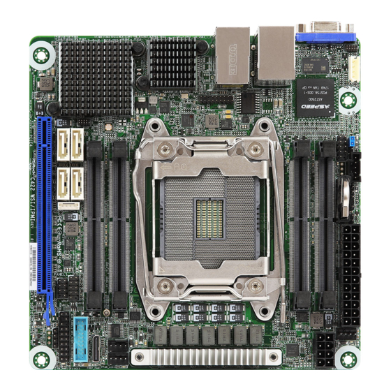
1.4 Motherboard Layout Front View 17.0cm (6.7 in) BMC_DIS1 ATXPWR1 NMI_BTN1 PSU_SMB1 IPMB_1 BATTERY CPU_FAN1 COM1 DDR4_A1 (64 bit, 260-pin module) ATX12V1 DDR4_B1 (64 bit, 260-pin module) USB 3.0 IPMI T: USB2 B: USB1 LAN1 LAN2 TPMS1 CPU1 DDR4_D1 (64 bit, 260-pin module) FRNT_FAN2 FRNT_FAN1 DDR4_C1 (64 bit, 260-pin module) OCU1... - Page 13 C422 WSI/IPMI / X299 WSI/IPMI Rear View NUT110_2...
- Page 14 Description Intelligent Platform Management Bus header (IPMB1_1) COM Port Header (COM1) Enable/Disable BMC Jumper (BMC_DIS1) PSU SMBus Header (PSU_SMB1) Non Maskable Interrupt Button (NMI_BTN1) ATX Power Connector (ATXPWR1) CPU Fan Connector (CPU_FAN1) ATX 12V Power Connector (ATX12V1) 2 x 260-pin DDR4 SO-DIMM Slots (DDR4_A1, DDR4_B1) Front Fan Connector (FRNT_FAN2) Front Fan Connector (FRNT_FAN1) 2 x 260-pin DDR4 SO-DIMM Slots (DDR4_C1, DDR4_D1)
-
Page 15: Onboard Led Indicators
C422 WSI/IPMI / X299 WSI/IPMI 1.5 Onboard LED Indicators ATXPWR1 C422 WSI Item Status Description CPU_FAN_LED1 Amber CPU_FAN1 failed FFAN_LED2 Amber FRNT_FAN2 failed FFAN_LED1 Amber FRNT_FAN1 failed SB_PWR1 Green STB PWR ready... -
Page 16: I/O Panel
1.6 I/O Panel No. Description No. Description VGA Port (VGA1) LAN RJ-45 Port (LAN1)** LAN RJ-45 Port (IPMI_LAN)* LAN RJ-45 Port (LAN2)** USB 3.0 Ports (USB3_1_2) LAN Port LED Indications *There are two LED next to the LAN port. Please refer to the table below for the LAN port LED indications. - Page 17 C422 WSI/IPMI / X299 WSI/IPMI **There are two LEDs on each LAN port. Please refer to the table below for the LAN port LED indications. ACT/LINK LED SPEED LED LAN Port LAN Port LED Indications Activity / Link LED Speed LED...
-
Page 18: Block Diagram
1.7 Block Diagram... -
Page 19: Chapter 2 Installation
C422 WSI/IPMI / X299 WSI/IPMI Chapter 2 Installation This is a mini ITX form factor (6.7'' x 6.7'', 17.02 cm x 17.02 cm) motherboard. Before you install the motherboard, study the configuration of your chassis to ensure that the motherboard fits into it. - Page 20 2.3 Installing the CPU 1. Before you insert the 2066-Pin CPU into the socket, please check if the PnP cap is on the socket, if the CPU surface is unclean, or if there are any bent pins in the socket. Do not force to insert the CPU into the socket if above situation is found.
- Page 21 C422 WSI/IPMI / X299 WSI/IPMI...
- Page 22 Please save and replace the cover if the processor is removed. The cover must be placed if you wish to return the motherboard for after service.
- Page 23 C422 WSI/IPMI / X299 WSI/IPMI 2.2 Installing the CPU Fan and Heatsink...
-
Page 24: Installation Of Memory Modules (Sodimm)
2.3 Installation of Memory Modules (SODIMM) This motherboard provides four 260-pin DDR4 (Double Data Rate 4) SO-DIMM slots, and supports Daul Channel Memory Technology. 1. For dual channel configuration, you always need to install identical (the same brand, speed, size and chip-type) DDR4 SO-DIMM pairs. 2. - Page 25 C422 WSI/IPMI / X299 WSI/IPMI...
-
Page 26: Expansion Slot (Pci Express Slot)
2.4 Expansion Slot (PCI Express Slot) There is a PCI Express slot on this motherboard. PCIE slot: PCIE4 (PCIe 3.0 x16 slot) is used for PCI Express x16 lane width cards. Slot Generation Mechanical Electrical Source PCIE4 Installing an expansion card Step 1. -
Page 27: Jumper Setup
C422 WSI/IPMI / X299 WSI/IPMI 2.5 Jumper Setup The illustration shows how jumpers are setup. When the jumper cap is placed on the pins, the jumper is “Short”. If no jumper cap is placed on the pins, the jumper is “Open”. The illustration shows a 3-pin jumper whose pin1 and pin2 are “Short”... -
Page 28: Onboard Headers And Connectors
2.6 Onboard Headers and Connectors Onboard headers and connectors are NOT jumpers. Do NOT place jumper caps over these headers and connectors. Placing jumper caps over the headers and connectors will cause permanent damage to the motherboard. System Panel Header C onnec t t he power sw itch, PLED+ PLED-... - Page 29 C422 WSI/IPMI / X299 WSI/IPMI Auxiliary Panel Header This header supports multiple (18-pin AUX PANEL_1) functions on the front panel, (see p.6, No. 15) including the front panel SMB, internet status indicator and chassis intrusion pin. A. Front panel SMBus connecting pin (6-1 pin FPSMB) This header allows you to connect SMBus (System Management Bus) equipment.
- Page 30 Fan) connectors. If you plan FAN_SPEED_CONTROL to connect a 3-Pin CPU fan, please connect it to Pin 1-3. *For more details, please refer to the Cooler QVL list on the ASRock Rack website. Front Fan Connectors Please connect fan cables to the FAN_VOLTAGE...
- Page 31 C422 WSI/IPMI / X299 WSI/IPMI ATX Power Connector This motherboard provides a (24-pin ATXPWR1) 24-pin ATX power connector. (see p.6, No. 6) To use a 20-pin ATX power supply, please plug it along Pin 1 and Pin 13. ATX 12V Power...
- Page 32 ALERT PSU SMBus Header PSU SMBus monitors the SMBCLK (PSU_SMB1) status of the power supply, fan (see p.6, No. 4) and system temperature. SMBDATA Intelligent Platform This 4-pin connector is used IPMB_SDA IPMB_SCL Management Bus Header to provide a cabled base-board (4-pin IPMB1) or front panel connection for (see p.6, No.
-
Page 33: Driver Installation Guide
C422 WSI/IPMI / X299 WSI/IPMI With the introduction of the Intel VROC product, there are three modes of operation: HW key required Key features • Pass-thru only (no RAID) • LED Management Pass-thru Not needed • Hot Plug Support • RAID 0 support for Intel Fultondale NVMe SSDs • Pass-thru SKU features... -
Page 34: Dua Lan And Teaming Operation Guide
2.8 Dua LAN and Teaming Operation Guide Dual LAN with Teaming enabled on this motherboard allows two single connections to act as one single connection(s) for twice the transmission bandwidth, making data transmission more effective and improving the quality of transmission of distant images. -
Page 35: M.2_Ssd (Ngff) Module Installation Guide (M2_2)
C422 WSI/IPMI / X299 WSI/IPMI 2.9 M.2_SSD (NGFF) Module Installation Guide (M2_2) The M.2, also known as the Next Generation Form Factor (NGFF), is a small size and versatile card edge connector that aims to replace mPCIe and mSATA. The Socket (M2_2) supports M.2 SATA3 6.0 Gb/s module and M.2 PCI Express module up to Gen3 x4 (32 Gb/s). -
Page 36: Chapter 3 Uefi Setup Utility
Chapter 3 UEFI Setup Utility 3.1 Introduction Th is section explains how to use the UEFI SETUP UTILITY to confi gure your system. Th e UEFI chip on the motherboard stores the UEFI SETUP UTILITY. You may run the UEFI SETUP UTILITY when you start up the computer. -
Page 37: Navigation Keys
C422 WSI/IPMI / X299 WSI/IPMI 3.1.2 Navigation Keys Please check the following table for the function description of each navigation key. Navigation Key(s) Function Description Moves cursor left or right to select Screens Moves cursor up or down to select items... -
Page 38: Main Screen
3.2 Main Screen Once you enter the UEFI SETUP UTILITY, the Main screen will appear and display the system overview. The Main screen provides system overview information and allows you to set the system time and date. All screenshots in this document are provided for reference only, and may be different by models. -
Page 39: Oc Tweaker Screen (For X299 Wsi/Ipmi Only)
C422 WSI/IPMI / X299 WSI/IPMI 3.3 OC Tweaker Screen (for X299 WSI/IPMI only) In the OC Tweaker screen, you can set up overclocking features. Because the UEFI software is constantly being updated, the following UEFI setup screens and descriptions are for reference purpose only, and they may not exactly match what you see on your screen. - Page 40 Multi Core Enhancement Improve the system's performance by forcing the CPU to perform the highest frequency on all CPU cores simultaneously. Disable to reduce power consumption . CPU Ratio The CPU speed is determined by the CPU Ratio multiplied with the BCLK. Increasing the CPU Ratio will increase the internal CPU clock speed without affecting the clock speed of other components.
- Page 41 C422 WSI/IPMI / X299 WSI/IPMI BCLK Step Configure the BCLK step value. BCLK Reset Range Issue a reset when BCLK overclocking exceeds thie range. Stable Delay Configure the delay time after BCLK settings for stable signals. Unit: 1ms. CPU BCLK Amplitude Select BCLK amplitude for ClockGen CPU 0/1/2.
- Page 42 PCIE PLL ORT Overshoot Reduction Technology improves the BCLK signal to decrease overshoot/ undershoot. Default is Level 1. CPU Output Divider The default is set to 2 where the max BCLK is 1000 MHz, while divider 4 lowers the max BCLK to 500 MHz, while divider 10 lowers the max BCLK to 200 MHz, and divider 1 turns it into 2000 NHz.
- Page 43 C422 WSI/IPMI / X299 WSI/IPMI Intel SpeedStep Technology Intel SpeedStep technology allows processors to switch between multiple frequen- cies and voltage points for better power saving and heat dissipation. Intel Speed Shift Technology Disable: Hardware chooses a P-state based on OS Request (Legacy P-States)
- Page 44 Primary Plane Current Limit Configure the current limit of the CPU under Turbo Mode in ampere. A lower limit can protect the CPU and save power, while a higher limit may improve performance. Long Duration Power Limit Configure Package Power Limit 1 in watts. When the limit is exceeded, the CPU ratio will be lowered after a period of time.
- Page 45 C422 WSI/IPMI / X299 WSI/IPMI Primary Timing CAS# Latency (tCL) The time between sending a column address to the memory and the beginning of the data in response. RAS# to CAS# Delay (tRCD) The number of clock cycles required between the opening of a row of memory and accessing columns within it.
- Page 46 RAS to RAS Delay (tRRD_L) The number of clocks between two rows activated in different banks of the same rank. Write to Read Delay (tWTR) The number of clocks between the last valid write operation and the next read command to the same internal bank.
- Page 47 C422 WSI/IPMI / X299 WSI/IPMI from same rank separation parameter. tCCCD_WR_L Configure back to back CAS to CAS (i.e. READ to RAED or WRITE to WRITE) from same rank separation parameter. tRRDS Configure Back to back READ to READ from different subranks within the same logical rank separation parameter for LRDIMM.
- Page 48 tWRDS Back to back WRITE to READ from different subranks within the same logical rank separation parameter for LRDIMM. Min: 1 Max: 31 tWRDR Back to back WRITE to READ from different RANK separation parameter. tWRDD Configure Write to Read different DIMM dead cycle Back to back READ to WRITE from different DIMM separation parameter.
- Page 49 C422 WSI/IPMI / X299 WSI/IPMI RTL (B2) Configure round trip latency. RTL (C1) Configure round trip latency. RTL (C2) Configure round trip latency. RTL (D1) Configure round trip latency. RTL (D2) Configure round trip latency. IO-L (A1) Configure IO latency.
- Page 50 IO-L (D2) Configure IO latency. Advanced Setting ODT WR (A1) Configure the memory on die termination resistors' WR for A1. ODT WR (A2) Configure the memory on die termination resistors' WR for A2. ODT WR (B1) Configure the memory on die termination resistors' WR for B1. ODT WR (B2) Configure the memory on die termination resistors' WR for B2.
- Page 51 C422 WSI/IPMI / X299 WSI/IPMI ODT PARK (B2) Configure the memory on die termination resistors' PARK for A2. ODT PARK (C1) Configure the memory on die termination resistors' PARK for C1. ODT PARK (C2) Configure the memory on die termination resistors' PARK for C2.
- Page 52 ODT NOM (D2) Configure the memory on die termination resistors' NOM for channel D2. C/A Parity [Enable] - Enables DDR4 Command Address Parity. [Disable] - Disables this feature. [Auto] - Sets it to the MRC default setting; current default is Disable. Round Trip Latency Optimize Configure the Round Trip Latency Optimize setting.
- Page 53 C422 WSI/IPMI / X299 WSI/IPMI Attempt Fast Cold Boot [Enable] - Protions of memory reference code will be skipped when possible to increase boot speed on cold boots. [Disable] - Disable this feature. [Audo] - Sets it to the MRC default setting; current default is Disable.
- Page 54 Adaptive: Add voltage to the CPU when the system is under heavy loading. Override: The voltage is fixed. Vcore Voltage Additional Offset Configure the dynamic Vcore voltage added to the Vcore. Max = 1.000V Offset Prefix Sets the offset value as positive or negative. CPU Mesh Voltage Mode Configure the amount of voltage fed to the UNCores fo the processor including its cache.
- Page 55 C422 WSI/IPMI / X299 WSI/IPMI Offset Prefix Sets the offset value as positive or negative. CPU Integrated VR Faults Disable FIVR Faults to raise the threshold to trigger CPU over current protection and over voltage protection for better overclocking capabilities CPU Integrated VR Efficiency Mode Enable FIVR Efficiency Management for power saving.
-
Page 56: Advanced Screen
3.4 Advanced Screen In this section, you may set the configurations for the following items: CPU Configuration, IIO Configuration, Chipset Configuration, Storage Configuration, Super IO Configura- tion, Serial Port Console Redirection, H/W Monitor, Intel ME Information, ACPI Con- figuration, USB Configuration and Instant Flash. Setting wrong values in this section may cause the system to malfunction. -
Page 57: Cpu Configuration
C422 WSI/IPMI / X299 WSI/IPMI 3.4.1 CPU Configuration Intel Hyper Threading Technology Intel Hyper Threading Technology allows multiple threads to run on each core, so that the overall performance on threaded software is improved. Active Processor Cores Select the number of cores to enable in each processor package. - Page 58 multiple virtual systems. Intel Safer Mode Extensions (SMX) Safer Mode Extensions (SMX) provide a means for system software to launch an MLE and establish a measured environment within the platform to support trust decisions by end users. DCU Streamer Prefetcher DCU streamer prefetcher is an L1 data cache prefetcher (MSR 1A4h [2]).
-
Page 59: Iio Configuration
C422 WSI/IPMI / X299 WSI/IPMI 3.4.2 IIO Configuration PCIE4 This allows you to select PCIe port Bifuration for selected slots(s). -
Page 60: Chipset Configuration
3.4.3 Chipset Configuration Above 4GB MMIO BIOS Assignment Enable/Disable above 4GB MemoryMappedIO BIOS assignment. This is disabled automatically when Aperture Size is set to 2048MB. VT-d Intel Virtualization Technology for Directed I/O helps your virtual machine monitor better utilize hardware by improving application compatibility and reliability, and provid- ing additional levels of manageability, security, isolation, and I/O performance. - Page 61 C422 WSI/IPMI / X299 WSI/IPMI OCU1 Link Speed This allows you to configure OCU1 Slot Link Speed. Auto mode is optimizing for overclocking. PCIE ASPM Support This option enables or disables the ASPM support for all CPU downstream devices. PCH PCIE ASPM Support This option enables or disables the ASPM support for all PCH downstream devices.
-
Page 62: Storage Configuration
3.4.4 Storage Configuration SATA Controller(s) Use this item to enable or disable SATA Controllers. SATA/M.2_SATA Mode Selection Identify the SATA/M.2_SATA port is connected to Solid State Drive or Hard Disk Drive. Press <Ctrl+I> to enter RAID ROM during UEFI POST process. SATA Aggressive Link Power Management Use this item to enable or disable SALP. -
Page 63: Super Io Configuration
C422 WSI/IPMI / X299 WSI/IPMI 3.4.5 Super IO Configuration Serial Port 1 Configuration Use this item to set parameters of Serial Port 1 (COM1). Serial Port Use this item to enable or disable the serial port. Change Settings Use this item to select an optimal setting for Super IO device. -
Page 64: Serial Port Console Redirection
3.4.6 Serial Port Console Redirection COM0 / COM1 Console Redirection Use this option to enable or disable Console Redirection. If this item is set to Enabled, you can select a COM Port to be used for Console Redirection. Console Redirection Settings Use this option to configure Console Redirection Settings, and specify how your computer and the host computer to which you are connected exchange information. - Page 65 C422 WSI/IPMI / X299 WSI/IPMI Bits Per Second Use this item to select the serial port transmission speed. The speed used in the host computer and the client computer must be the same. Long or noisy lines may require lower transmission speed.
- Page 66 Legacy Console Redirection Legacy Console Redirection Settings Use this option to configure Legacy Console Redirection Settings, and specify how your computer and the host computer to which you are connected exchange information. Legacy Serial Redirection Port Use this item to select a COM port to display redirection of Legacy OS and Legacy OPROM Messages.
-
Page 67: H/W Monitor
C422 WSI/IPMI / X299 WSI/IPMI 3.4.7 H/W Monitor In this section, it allows you to monitor the status of the hardware on your system, includ- ing the parameters of the CPU temperature, motherboard temperature, CPU fan speed, chassis fan speed, and the critical voltage. - Page 68 Smart Fan Temp Control Smart Fan Temp x (x means 1 to 11 stage) This allows you to set temperature for each stage. Watch Dog Timer This allows you to enable or disable the Watch Dog Timer. The default value is [Disabled]..
-
Page 69: Intel Me Information
C422 WSI/IPMI / X299 WSI/IPMI 3.4.8 Intel ME Information Intel ME Information screen displays the Intel ME Configuration information, such as Operational Firmware Version and Firmware State. -
Page 70: Acpi Configuration
3.4.9 ACPI Configuration PCIE Devices Power On Allow the system to be waked up by a PCIE device and enable wake on LAN. Ring-In Power On Allow the system to be waked up by onboard COM port modem Ring-In signals. RTC Alarm Power On Allow the system to be waked up by the real time clock alarm. -
Page 71: Usb Configuration
C422 WSI/IPMI / X299 WSI/IPMI 3.4.10 USB Configuration Legacy USB Support Enable or disable Legacy OS Support for USB 2.0 devices. If you encounter USB compatibility issues it is recommended to disable legacy USB support. Select UEFI Setup Only to support USB devices under the UEFI setup and Windows/Linux operating systems only. -
Page 72: Instant Flash
3.4.11 Instant Flash Instant Flash is a UEFI flash utility embedded in Flash ROM. This convenient UEFI update tool allows you to update system UEFI without entering operating systems ® first like MS-DOS or Windows . Just save the new UEFI file to your USB flash drive, floppy disk or hard drive and launch this tool, then you can update your UEFI only in a few clicks without preparing an additional floppy diskette or other compli- cated flash utility. -
Page 73: Security
C422 WSI/IPMI / X299 WSI/IPMI 3.5 Security In this section, you may set or change the supervisor/user password for the system. For the user password, you may also clear it. Supervisor Password Set or change the password for the administrator account. Only the administrator has authority to change the settings in the UEFI Setup Utility. -
Page 74: Boot Screen
3.6 Boot Screen This section displays the available devices on your system for you to configure the boot settings and the boot priority. Boot Option #1 Use this item to set the system boot order. Boot Option #2 Use this item to set the system boot order. Boot Option #3 Use this item to set the system boot order. - Page 75 C422 WSI/IPMI / X299 WSI/IPMI Boot From Onboard LAN Allow the system to be waked up by the onboard LAN. Setup Prompt Timeout Configure the number of seconds to wait for the setup hot key. Bootup Num-Lock Select whether Num Lock should be turned on or off when the system boots up.
- Page 76 CSM (Compatibility Support Module) Enable to launch the Compatibility Support Module. Please do not disable unless you’re running a WHCK test. Launch Other Storage OpROM Policy Select UEFI only to run those that support UEFI option ROM only. Select Legacy only to run those that support legacy option ROM only.
- Page 77 C422 WSI/IPMI / X299 WSI/IPMI M.2_1 Slot OpROM Use this item to select slot storage and Network Option ROM policy. In Auto option, the default is Disabled with NVMe device, but it is Legacy with other devices. (This item can't select Video Option ROM policy.)
-
Page 78: Server Mgmt
3.7 Server Mgmt Wait For BMC Wait For BMC response for specified time out. BMC starts at the same time when BIOS starts during AC power ON. It takes around 90 seconds to initialize Host to BMC interfaces. Inventory Support This will execute inventory function for system. -
Page 79: System Event Log
C422 WSI/IPMI / X299 WSI/IPMI 3.7.1 System Event Log SEL Components Change this to enable ro disable event logging for error/progress codes during boot. Erase SEL Use this to choose options for earsing SEL. When SEL is Full Use this to choose options for reactions to a full SEL. -
Page 80: Bmc Network Configuration
3.7.2 BMC Network Configuration BMC Out of Band Access Enabled/Disabled BMC Out of band Access. Lan Channel (Failover) Manual Setting IPMI LAN If [No] is selected, the IP address is assigned by DHCP. If you prefer using a static IP address, toggle to [Yes], and the changes take effect after the system reboots. -
Page 81: Event Logs
C422 WSI/IPMI / X299 WSI/IPMI 3.8 Event Logs Change Smbios Event Log Settings This allows you to configure the Smbios Event Log Settings. When entering the item, you will see the followings: Smbios Event Log Use this item to enable or disable all features of the SMBIOS Event Logging during system boot. - Page 82 View Smbios Event Log Press <Enter> to view the Smbios Event Log records. All values changed here do not take effect until computer is restarted.
-
Page 83: Exit Screen
C422 WSI/IPMI / X299 WSI/IPMI 3.9 Exit Screen Save Changes and Exit When you select this option, the following message “Save configuration changes and exit setup?” will pop-out. Press <F10> key or select [Yes] to save the changes and exit the UEFI SETUP UTILITY. -
Page 84: Chapter 4 Software Support
4.2.4 Contact Information If you need to contact ASRock Rack or want to know more about ASRock Rack, welcome to visit ASRock Rack’s website at http://www.ASRockRack.com; or you may contact your... - Page 85 C422 WSI/IPMI / X299 WSI/IPMI Chapter 5 Troubleshooting 5.1 Troubleshooting Procedures Follow the procedures below to troubleshoot your system. Always unplug the power cord before adding, removing or changing any hardware com- ponents. Failure to do so may cause physical injuries to you and damages to motherboard components.
- Page 86 1. Verify if the battery on the motherboard provides ~3VDC. Install a new battery if it does not. 2. Confirm whether your power supply provides adaquate and stable power. Other problems... 1. Try searching keywords related to your problem on ASRock Rack’s FAQ page: http://www.asrockrack.com/support...
- Page 87 C422 WSI/IPMI / X299 WSI/IPMI 5.2 Technical Support Procedures If you have tried the troubleshooting procedures mentioned above and the problems are still unsolved, please contact ASRock Rack’s technical support with the following information: 1. Your contact information 2. Model name, BIOS version and problem type.
Need help?
Do you have a question about the C422 WSI/IPMI and is the answer not in the manual?
Questions and answers