Table of Contents
Advertisement
Quick Links
Download this manual
See also:
Installation Manual
Advertisement
Table of Contents

Related Manuals for ASROCK Rack EP2C612D16NM


Summary of Contents for ASROCK Rack EP2C612D16NM
-
Page 1: User Manual
EP2C612D16NM EP2C612D16NM-8R EP2C612D16NM-2T EP2C612D16NM-2T8R User Manual Version 1.0 Published September 2016 Copyright©2016 ASRock Rack INC. All rights reserved. -
Page 2: Copyright Notice
In no event shall ASRock Rack, its directors, officers, employees, or agents be liable for any indirect, special, incidental, or consequential damages (including damages for loss of... - Page 3 Contact Information If you need to contact ASRock Rack or want to know more about ASRock Rack, you’re welcome to visit ASRock Rack’s website at www.ASRockRack.com; or you may contact your dealer for further information. ASRock Rack Incorporation 6F., No.37, Sec. 2, Jhongyang S. Rd., Beitou District,...
-
Page 4: Table Of Contents
Contents Chapter 1 Introduction Package Contents Specifications Unique Features Motherboard Layout Onboard LED Indicators I/O Panel Block Diagram Chapter 2 Installation Screw Holes Pre-installation Precautions Installing the CPU Installing the CPU Fan and Heatsink Installation of Memory Modules (DIMM) Jumper Setup Onboard Headers and Connectors Dr. - Page 5 Main Screen Advanced Screen 3.3.1 ACPI Configuration 3.3.2 Configure Super IO Settings 3.3.3 Serial Port Console Redirection 3.3.4 CSM Parameters 3.3.5 Trusted Computing 3.3.6 USB Configuration 3.3.7 System Configuration 3.3.8 Hard Disk S.M.A.R.T Settings 3.3.9 3rd Storage Configuration 3.3.10 H/W Monitor 3.3.11 WHEA Configuration 3.3.12 Instant Flash IntelRCSetup...
- Page 6 3.5.2 BMC Network Configuration Security Boot Screen Event Logs Exit Screen Chapter 4 Software Support Install Operating System Support CD Information 4.2.1 Running The Support CD 4.2.2 Drivers Menu 4.2.3 Utilities Menu 4.2.4 Contact Information Chapter 5 Troubleshooting Troubleshooting Procedures Technical Support Procedures Returning Merchandise for Service Chapter 6 Net Framework Installation Guide...
-
Page 7: Chapter 1 Introduction
In case any modifications of this manual occur, the updated version will be available on ASRock Rack website without further notice. You may find the latest memory and CPU support lists on ASRock Rack website as well. ASRock Rack’s Website: www.ASRockRack.com If you require technical support related to this motherboard, please visit our website for specific information about the model you are using. -
Page 8: Specifications
1.2 Specifications EP2C612D16NM / EP2C612D16NM-8R / EP2C612D16NM-2T / EP2C612D16NM-2T8R MB Physical Status Form Factor SSI EEB Dimension 12'' x 13'' (30.5 cm x 33.0 cm) Processor System Intel® Xeon processor E5-2600/4600 & v3/v4 series Socket Dual Socket LGA 2011 R3 Chipset Intel®... - Page 9 EP2C612D16NM Series EP2C612D16NM-2T8R / EP2C612D16NM-2T: 2 x RJ45 10GLAN by Intel® X540 1 x RJ45 Dedicated IPMI LAN port - Supports Wake-On-LAN - Supports Energy Efficient Ethernet 802.3az - Supports Dual LAN with Teaming function - Supports PXE - LAN1 supports NCSI EP2C612D16NM / EP2C612D16NM-8R: - 2 x RJ45 GLAN by Intel®...
- Page 10 128Mb AMI UEFI Legal BIOS BIOS Features - Plug and Play (PnP) - ACPI 2.0 Compliance Wake Up Events - SMBIOS 2.8 Support - ASRock Rack Instant Flash Hardware Monitor Temperature - CPU Temperature Sensing - MB Temperature Sensing - Card Side Temperature Sensing...
- Page 11 EP2C612D16NM Series This motherboard supports Wake from on Board LAN. To use this function, please make sure that the “Wake on Magic Packet from power off state” is enabled in Device Manager > Intel® Ethernet Connection > Power Management. And the “PCI Devices Power On” is enabled in UEFI SETUP UTILITY >...
-
Page 12: Unique Features
POST or the <F2> key to enter into the BIOS setup menu to access ASRock Rack Instant Flash. Just launch this tool and save the new BIOS file to your USB flash drive, floppy disk or hard drive, then you can update your BIOS only in a few clicks without preparing an additional floppy diskette or other complicated flash utility. -
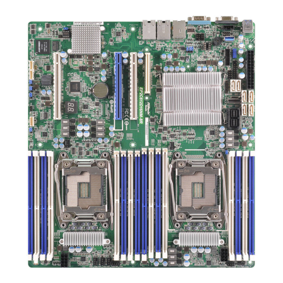
Page 13: Motherboard Layout
EP2C612D16NM Series 1.4 Motherboard Layout EP2C612D16NM 15 16 3 4 5 6 9 10 121314 33.02 cm (13 in) SATA_1 SATA_0 USB 3.0 DDR4_A1 (64 bit, 288-pin module, Blue) ATXPWR1 T: USB2 B: USB1 DDR4_A2 (64 bit, 288-pin module, White) - Page 14 EP2C612D16NM-2T 3 4 5 6 9 10 121314 15 16 33.02 cm (13 in) SATA_0 SATA_1 USB 3.0 ATXPWR1 DDR4_A1 (64 bit, 288-pin module, Blue) T: USB2 B: USB1 DDR4_A2 (64 bit, 288-pin module, White) SATA_3 SATA_2 SATA_4 DDR4_B1 (64 bit, 288-pin module, Blue)
- Page 15 EP2C612D16NM Series Description Speaker Header (SPEAKER1) LAN LED Connector (LED_LAN34) Vertical Type A USB 3.0 (USB3_5) USB 3.0 Header (USB3_3_4) USB 2.0 Header (USB_1_2) Auxiliary Panel Header (AUX_PANEL1) ATX Power Connector (ATXPWR1) SATA3 Connector (SATA_5) SATA3 Connector (SATA_4) SATA3 Connector (SATA_1)
- Page 16 Description 2 x 288-pin DDR4 DIMM Slots (DDR4_H2, DDR4_G2, White) 2 x 288-pin DDR4 DIMM Slots (DDR4_H1, DDR4_G1, Blue) CPU 2 Fan Connector (CPU2_FAN1) Intelligent Platform Management Bus header (IPMB1) ME Recovery Jumper (ME_RECOVERY1) Thermal Sensor Header (TR1) Chassis ID3 Jumper (CHASSIS_ID3) Chassis ID2 Jumper (CHASSIS_ID2) Chassis ID1 Jumper (CHASSIS_ID1) BMC SMBus Header 1 (BMC_SMB1)
- Page 17 EP2C612D16NM Series EP2C612D16NM-8R 3 4 5 6 9 10 121314 1516 17 33.02 cm (13 in) SATA_1 SATA_0 USB 3.0 ATXPWR1 DDR4_A1 (64 bit, 288-pin module, Blue) T: USB2 B: USB1 DDR4_A2 (64 bit, 288-pin module, White) SATA_3 SATA_2 SATA_4...
- Page 18 EP2C612D16NM-2T8R 3 4 5 6 9 10 121314 1516 17 33.02 cm (13 in) SATA_1 SATA_0 USB 3.0 ATXPWR1 DDR4_A1 (64 bit, 288-pin module, Blue) T: USB2 B: USB1 DDR4_A2 (64 bit, 288-pin module, White) SATA_3 SATA_2 SATA_4 DDR4_B1 (64 bit, 288-pin module, Blue)
- Page 19 EP2C612D16NM Series Description Speaker Header (SPEAKER1) LAN LED Connector (LED_LAN34) Vertical Type A USB 3.0 (USB3_5) USB 3.0 Header (USB3_3_4) USB 2.0 Header (USB_1_2) Auxiliary Panel Header (AUX_PANEL1) ATX Power Connector (ATXPWR1) SATA3 Connector (SATA_5) SATA3 Connector (SATA_4) SATA3 Connector (SATA_1)
- Page 20 Description ATX 12V Power Connector (ATX12V2) 2 x 288-pin DDR4 DIMM Slots (DDR4_H2, DDR4_G2, White) 2 x 288-pin DDR4 DIMM Slots (DDR4_H1, DDR4_G1, Blue) CPU 2 Fan Connector (CPU2_FAN1) Intelligent Platform Management Bus header (IPMB1) ME Recovery Jumper (ME_RECOVERY1) Thermal Sensor Header (TR1) Chassis ID3 Jumper (CHASSIS_ID3) Chassis ID2 Jumper (CHASSIS_ID2) Chassis ID1 Jumper (CHASSIS_ID1)
-
Page 21: Onboard Led Indicators
EP2C612D16NM Series 1.5 Onboard LED Indicators SATA_1 SATA_0 USB 3.0 ATXPWR1 DDR4_A1 (64 bit, 288-pin module, Blue) T: USB2 B: USB1 DDR4_A2 (64 bit, 288-pin module, White) SATA_3 SATA_2 SATA_4 FAN_LED5 DDR4_B1 (64 bit, 288-pin module, Blue) AUX_PANEL1 DDR4_B2 (64 bit, 288-pin module, White) - Page 22 Status Description Amber FRNT_FAN1 failed Amber FRNT_FAN2 failed Amber CPU1_FAN1 failed Amber FRNT_FAN3 failed Amber FRNT_FAN4 failed Amber FRNT_FAN5 failed Amber FRNT_FAN6 failed Amber CPU2_FAN1 failed Green BMC heartbeat LED Green STB PWR ready...
-
Page 23: I/O Panel
EP2C612D16NM Series 1.6 I/O Panel EP2C612D16NM / EP2C612D16NM-8R No. Description No. Description USB 3.0 Ports (USB3_1_2) LAN RJ-45 Port (IPMI_LAN1)* VGA Port (VGA1) 1G LAN RJ-45 Port(LAN1)** Serial Port (COM1) 1G LAN RJ-45 Port (LAN2)** EP2C612D16NM-2T / EP2C612D16NM-2T8R No. Description No. - Page 24 **There are two LEDs on each LAN port. Please refer to the table below for the LAN port LED indications. SPEED LED ACT/LINK LED LAN Port LAN Port (LAN1, LAN2) LED Indications 1G For EP2C612D16NM / EP2C612D16NM-8R Speed LED Activity / Link LED Status Description Status...
-
Page 25: Block Diagram
EP2C612D16NM Series 1.7 Block Diagram EP2C612D16NM... - Page 26 EP2C612D16NM-8R...
- Page 27 EP2C612D16NM Series EP2C612D16NM-2T...
- Page 28 EP2C612D16NM-2T8R...
-
Page 29: Chapter 2 Installation
EP2C612D16NM Series Chapter 2 Installation This is a SSI EEB form factor (12” x 13”, 30.5 cm x 33.0 cm) motherboard. Before you install the motherboard, study the configuration of your chassis to ensure that the motherboard fits into it. -
Page 30: Installing The Cpu
2.3 Installing the CPU 1. Before you insert the 2011-3-Pin CPU into the socket, please check if the PnP cap is on the socket, if the CPU surface is unclean, or if there are any bent pins in the socket. Do not force to insert the CPU into the socket if above situation is found. - Page 31 EP2C612D16NM Series...
- Page 32 The cover must be placed if returning the motherboard for after service.
-
Page 33: Installing The Cpu Fan And Heatsink
EP2C612D16NM Series 2.4 Installing the CPU Fan and Heatsink Before you installed the heatsink, you need to spray thermal interface material between the CPU and the heatsink to improve heat dissipation. -
Page 34: Installation Of Memory Modules (Dimm)
2.5 Installation of Memory Modules (DIMM) This motherboard provides sixteen 288-pin DDR4 (Double Data Rate 4) DIMM slots in two groups, and supports Dual Channel Memory Technology. Capacity CPU1 CPU2 DDR4_A1, B1, C1, D1 (Blue) DDR4_E1, F1, G1, H1 (Blue) 256GB / 512GB DDR4_A2, B2, C2, D2 (White) - Page 35 EP2C612D16NM Series The DIMM only fits in one correct orientation. It will cause permanent damage to the motherboard and the DIMM if you force the DIMM into the slot at incorrect orientation.
-
Page 36: Recommended Memory Configurations
Recommended Memory Configurations A single memory module should be installed in the BLUE socket. If you install only one CPU (CPU1) on the motherboard, make sure to install DIMMs into DDR4_A, DDR4_B, DDR4_C, or DDR4_D slot(s). Memory can speed up to 2133 MHz for 1 DIMM per channel. For two DIMMs per channel, memory speed should be 1866MHz. -
Page 37: Jumper Setup
EP2C612D16NM Series 2.6 Jumper Setup The illustration shows how jumpers are setup. When the jumper cap is placed on the pins, the jumper is “Short”. If no jumper cap is placed on the pins, the jumper is “Open”. The illustration shows a 3-pin jumper whose pin1 and pin2 are “Short”... - Page 38 Chassis ID1 Jumper (3-pin CHASSIS_ID1) Chassis ID2 Jumper (3-pin CHASSIS_ID2) Chassis ID3 Jumper (3-pin CHASSIS_ID3) Board Level SKU (Default) Reserved for system level Chassis ID1 Jumper (3-pin CHASSIS_ID1) Chassis ID2 Jumper (3-pin CHASSIS_ID2) Chassis ID3 Jumper (3-pin CHASSIS_ID3) Reserved for system level Reserved for system level Chassis ID1 Jumper (3-pin CHASSIS_ID1)
-
Page 39: Onboard Headers And Connectors
EP2C612D16NM Series 2.7 Onboard Headers and Connectors Onboard headers and connectors are NOT jumpers. Do NOT place jumper caps over these headers and connectors. Placing jumper caps over the headers and connectors will cause permanent damage to the motherboard. *Please see p.7, p.10 or p.11 for motherboard layout. - Page 40 Auxiliary Panel Header This header supports multiple (18-pin AUX PANEL_1) functions on the front panel, including the front panel SMB, internet status indicator and chassis intrusion pin. A. Front panel SMBus connecting pin (6-1 pin FPSMB) This header allows you to connect SMBus (System Management Bus) equipment. It can be used for communication between peripheral equipment in the system, which has slower transmission rates, and power management equipment.
- Page 41 EP2C612D16NM Series Mini SAS HD Connector This Mini SAS HD connector LSI_SAS_0_7 (LSI_SAS_0_7) supports SAS/ SATA data *Not supported for EP2C612D- cables for internal storage 16NM motherboard devices. The current SAS3/SATA3 interface allows up to 12.0 Gb/s data transfer rate. For connecting SAS HDDs, please contact SAS data cable dealers.
- Page 42 CPU_F AN_SPEED FAN_SPEED_CONTROL please connect it to Pin 1-3. *For more details, please refer to the Cooler QVL list on the ASRock Rack website. Front Fan Connectors Please connect fan cables to the (4-pin FRNT_FAN1) fan connectors and match the...
- Page 43 EP2C612D16NM Series ATX Power Connector This motherboard provides a (24-pin ATXPWR1) 24-pin ATX power connector. To use a 20-pin ATX power supply, please plug it along Pin 1 and Pin 13. ATX 12V Power This motherboard provides Connectors two 8-pin ATX 12V power (8-pin ATX12V1) connectors.
- Page 44 Intelligent Platform IPMB_SDA This 4-pin connector is used IPMB_SCL Management Bus header to provide a cabled base-board (4-pin IPMB1) or front panel connection for value added features and 3rd- No Connect party add-in cards, such as Emergency Management cards, t h a t p r o v i d e m a n a g e m e n t features using the IPMB.
-
Page 45: Dr. Debug
EP2C612D16NM Series 2.8 Dr. Debug Dr. Debug is used to provide code information, which makes troubleshooting even easier. Please see the diagrams below for reading the Dr. Debug codes. Code Description Please check if the CPU is installed correctly and then clear CMOS. -
Page 46: Driver Installation Guide
2.9 Driver Installation Guide To install the drivers to your system, please insert the support CD to your optical drive first. Then, the drivers compatible to your system can be auto-detected and listed on the support CD driver page. Please follow the order from top to bottom to install those required drivers. -
Page 47: Dual Lan And Teaming Operation Guide
EP2C612D16NM Series 2.10 Dual LAN and Teaming Operation Guide Dual LAN with Teaming enabled on this motherboard allows two single connections to act as one single connection for twice the transmission bandwidth, making data transmission more effective and improving the quality of transmission of distant images. -
Page 48: Chapter 3 Uefi Setup Utility
Chapter 3 UEFI Setup Utility 3.1 Introduction Th is section explains how to use the UEFI SETUP UTILITY to confi gure your system. Th e UEFI chip on the motherboard stores the UEFI SETUP UTILITY. You may run the UEFI SETUP UTILITY when you start up the computer. -
Page 49: Navigation Keys
EP2C612D16NM Series 3.1.2 Navigation Keys Please check the following table for the function description of each navigation key. Navigation Key(s) Function Description Moves cursor left or right to select Screens Moves cursor up or down to select items + / - To change option for the selected items <Tab>... -
Page 50: Main Screen
3.2 Main Screen Once you enter the UEFI SETUP UTILITY, the Main screen will appear and display the system overview. The Main screen provides system overview information and allows you to set the system time and date. -
Page 51: Advanced Screen
EP2C612D16NM Series 3.3 Advanced Screen In this section, you may set the configurations for the following items: ACPI Configura- tion, Configure Super IO Settings, Serial Port Console Redirection, CSM Parameters, Trusted Computing, USB Configuration, System Configuration, Hard Disk S.M.A.R.T Set- tings, 3rd Storage Configuration, H/W Monitor, WHEA Configuration and Instant Flash. -
Page 52: Acpi Configuration
3.3.1 ACPI Configuration PCIE Devices Power On Use this item to enable or disable PCIE devices to turn on the system from the power-soft- off mode. Ring-In Power On Use this item to enable or disable Ring-In signals to turn on the system from the power- soft-off mode. -
Page 53: Configure Super Io Settings
EP2C612D16NM Series 3.3.2 Configure Super IO Settings Serial Port 1 Configuration Use this item to configure the onboard serial port 1. Select and enter the "Serial Port 1 Configuration" and you will see the followings: Serial Port Use this item to enable or disable the onboard serial port. -
Page 54: Serial Port Console Redirection
3.3.3 Serial Port Console Redirection COM1 / SOL Console Redirection Use this option to enable or disable Console Redirection. If this item is set to Enabled, you can select a COM Port to be used for Console Redirection. Console Redirection Settings Use this option to configure Console Redirection Settings, and specify how your computer and the host computer to which you are connected exchange information. -
Page 55: Flow Control
EP2C612D16NM Series computer and the client computer must be the same. Long or noisy lines may require lower transmission speed. The options include [9600], [19200], [57600], [115200] and [38400]. Data Bits Use this item to set the data transmission size. The options include [7] and [8] (Bits). -
Page 56: Console Redirection
Serial Port for Out-of-Band Management/Windows Emergency Management Services (EMS) Console Redirection Use this option to enable or disable Console Redirection. If this item is set to Enabled, you can select a COM Port to be used for Console Redirection. Console Redirection Settings Use this option to configure Console Redirection Settings, and specify how your computer and the host computer to which you are connected exchange information. -
Page 57: Csm Parameters
EP2C612D16NM Series 3.3.4 CSM Parameters Boot Option Filter This option controls Legacy/UEFI ROMs priority. Launch Storage OpROM Policy Select UEFI only to run those that support UEFI option ROM only. Select Legacy only to run those that support legacy option ROM only. Select Do not launch to not execute both legacy and UEFI option ROM. -
Page 58: Trusted Computing
3.3.5 Trusted Computing NOTE: Options vary depending on the version of your connected TPM module. Here is an example of TPM2.0. TPM State Use this item to enable or disable Security Device. NOTE: Your computer will reboot during restart in order to change State of the Device. Pending Operation Schedule an Operation for the Security Device. - Page 59 EP2C612D16NM Series Device Select TPM 1.2 will restrict support to TPM 1.2 devices; TPM 2.0 will restrict support to TPM 2.0 devices; Auto will support both with the default set to TPM 2.0 devices. If TPM 2.0 devices are not found, TPM 1.2 devices will be enumerated.
-
Page 60: Usb Configuration
3.3.6 USB Configuration Intel USB3.0 Mode Use this item to select the mode of operation of Intel USB 3.0 controller. Configuration options: [Enabled], [Disabled], [Auto] and [Smart Auto]. If [Auto] is selected, all USB ports work as USB3.0 after boot to OS. If [Smart Auto] is selected, all USB ports work as USB3.0 after boot to OS and work as USB2.0 in deep sleep stages. -
Page 61: System Configuration
EP2C612D16NM Series 3.3.7 System Configuration Primary Graphics Adapter Use this item to select the type and primary VGA in case of multiple video contorllers. Onboard VGA Use this to enable or disable the Onboard VGA function. The default value is [Auto]. - Page 62 State] is selected, it will recover to the state before AC/power loss. Onboard Debug Port LED Enable or disable the onboard Dr. Debug LED.
-
Page 63: Hard Disk S.m.a.r.t Settings
EP2C612D16NM Series 3.3.8 Hard Disk S.M.A.R.T Settings Hard Disk S.M.A.R.T. Use this item to enable or disable the S.M.A.R.T. (Self-Monitoring, Analysis, and Reporting Technology) feature. Configuration options: [Disabled] and [Enabled]. -
Page 64: 3Rd Storage Configuration
3.3.9 3rd Storage Configuration LSI 3008 Controller Use this item to enable or disable LSI 3008 Controller. Press <Ctrl - C> to enter RAID ROM during UEFI POST process. Bootable LSI 3008 Controller Use this item to enable or disable Bootable LSI Controller. -
Page 65: H/W Monitor
EP2C612D16NM Series 3.3.10 H/W Monitor In this section, it allows you to monitor the status of the hardware on your system, includ- ing the parameters of the CPU temperature, motherboard temperature, CPU fan speed, chassis fan speed, and the critical voltage. -
Page 66: Watch Dog Timer
FRNT_FAN 4 This allows you to set the front fan 4’s speed. The default value is [Smart Fan]. FRNT_FAN 5 This allows you to set the front fan 5’s speed. The default value is [Smart Fan]. FRNT_FAN 6 This allows you to set the front fan 6’s speed. The default value is [Smart Fan]. Smart Fan Control This allows you to set the Smart fan’s level speed. -
Page 67: Whea Configuration
EP2C612D16NM Series 3.3.11 WHEA Configuration WHEA Support Use this item to enable or disable Windows Hardware Error Architecture. System Error Use this item to enable or disable System Error feature. When it is set to [Enabled], you can configure Memory Error and PCIE Error log features. -
Page 68: Instant Flash
3.3.12 Instant Flash Instant Flash is a UEFI flash utility embedded in Flash ROM. This convenient UEFI update tool allows you to update system UEFI without entering operating systems ® first like MS-DOS or Windows . Just save the new UEFI file to your USB flash drive, floppy disk or hard drive and launch this tool, then you can update your UEFI only in a few clicks without preparing an additional floppy diskette or other compli- cated flash utility. -
Page 69: Intelrcsetup
EP2C612D16NM Series 3.4 IntelRCSetup In this section, you may set the configurations for the following items: Processor Configu- ration, CPU Power Management Configuration, QPI Configuration, Memory Configura- tion, IIO Configuration, PCH Configuration and Server ME Configuration. -
Page 70: Processor Configuration
3.4.1 Processor Configuration Per-Socket Configuration Change Per-Socket Settings. CPU Socket 1 Configuration Active Processor Cores Enter the number of cores to be enabled. 0 means all cores. 14 cores are available. CPU Socket 2 Configuration Active Processor Cores Enter the number of cores to be enabled. 0 means all cores. 14 cores are available. Intel Hyper Threading Technology Intel Hyper Threading Technology allows multiple threads to run on each core, so that the overall performance on threaded software is improved. -
Page 71: Intel Virtualization Technology
EP2C612D16NM Series No-Execute Memory Protection Processors with No-Execution Memory Protection Technology may prevent certain classes of malicious buffer overflow attacks. Enable Intel TXT Support Enable Intel Trusted Execution Technology configuration. Please disable "EX DFX Features" when TXT is enabled. Intel Virtualization Technology... -
Page 72: Cpu Power Management Configuration
3.4.2 CPU Power Management Configuration Intel SpeedStep Technology Intel SpeedStep technology is Intel’s new power saving technology. Processors can switch between multiple frequencies and voltage points to enable power saving. The default value is [Enabled]. Configuration options: [Enabled] and [Disabled]. If you install Windows® Vista / 7 / 8 and want to enable this function, please set this item to [Enabled]. - Page 73 EP2C612D16NM Series CPU C6 State Support Enable C6 deep sleep state for lower power consumption. CPU Thermal Throttling Enable CPU internal thermal control mechanisms to keep the CPU from overheating. CPU HWPM State Control CPU HWPM State Control controls configuration sub menu, includes Native and 00B nd etc.
-
Page 74: Qpi Configuration
3.4.3 QPI Configuration Link Speed Mode Select the QPI link speed as either the POR speed (Fast) or default speed (Slow). Link Frequency Select Allows for selecting the QPI Link Frequency. -
Page 75: Memory Configuration
EP2C612D16NM Series 3.4.4 Memory Configuration Enforce POR Enable to enforce POR restrictions for DDR4 frequency and voltage programming. DRAM Frequency ECC Support Use this item to enable or disable DDR ECC Support. Enable ADR Use this item to enable the ADR. - Page 76 RAS Mode Enable or disable RAS modes. Enabling Sparing and Mirroring is not supported. If enabled, Sparing will be selected. Memory Rank Sparing Enable or disable Memory Rank Sparing. Memory Power Saving Mode Use this item to configure CKE and related Memory Power Savings Features.
-
Page 77: Iio Configuration
EP2C612D16NM Series 3.4.5 IIO Configuration PCIE 2 Link Width This allows you to select PCIE 2 port Link Width. The default value is [Auto]. PCIE 2 Link Speed This allows you to select PCIE 2 Link Speed. The default value is [Auto]. - Page 78 PCI-E ASPM Support This option enables or disables the ASPM support for all downstream devices.
-
Page 79: Pch Configuration
EP2C612D16NM Series 3.4.6 PCH Configuration PCH sSATA Configuration sSATA devices and settings sSATA Controller Use this item to enable or disable SATA Controller. sSATA Mode Selection Identify the SATA port is connected to Solid State Drive or Hard Disk Drive. Press <Ctrl+I>... -
Page 80: Sata Controller
External SATA External SATA configuration. Spin Up Device If enabled for any of ports, Staggered Spin Up will be performed and only the drives which have this option enabled will spin up at boot. Otherwise all drives spin up at boot. sSATA Rx Setting Adjust sSATA DTLE DATA Values (0-15). - Page 81 EP2C612D16NM Series SATA Rx Setting Adjust SATA DTLE DATA Values (0-15). SATA Device Type Identify the SATA port connected to Solid State Drive or Hard Disk Drive.
-
Page 82: Server Me Configuration
3.4.7 Server ME Configuration Spread Spectrum Use this item to select spread specturm mode. -
Page 83: Server Mgmt
EP2C612D16NM Series 3.5 Server Mgmt Wait For BMC Wait For BMC response for specified time out. In PILOTII, BMC starts at the same time when BIOS starts during AC power ON. It takes around 30 seconds to initialize Host to... -
Page 84: System Event Log
3.5.1 System Event Log SEL Components Change this to enable ro disable all features of System Event Logging during boot. Erase SEL Use this to choose options for earsing SEL. When SEL is Full Use this to choose options for reactions to a full SEL. Log EFI Status Codes Use this item to disable the logging of EFI Status Codes or log only error code or only progress or both. -
Page 85: Bmc Network Configuration
EP2C612D16NM Series 3.5.2 BMC Network Configuration Lan Channel 1 (Failover) Manual setting IPMI LAN If [No] is selected, the IP address is assigned by DHCP. If you prefer using a static IP address, toggle to [Yes], and the changes take effect after the system reboots. The default value is [No]. - Page 86 The default login information for the IPMI web interface is: Username: admin Password: admin For more instructions on how to set up remote control environment and use the IPMI man- agement platform, please refer to the IPMI Configuration User Guide or go to the Support website at: http://www.asrockrack.com/support/ipmi.asp BMC Mac Backup Tool Use this to restore BMC Mac from the backup.
-
Page 87: Security
EP2C612D16NM Series 3.6 Security In this section, you may set or change the supervisor/user password for the system. For the user password, you may also clear it. Supervisor Password Set or change the password for the administrator account. Only the administrator has authority to change the settings in the UEFI Setup Utility. -
Page 88: Boot Screen
3.7 Boot Screen In this section, it will display the available devices on your system for you to configure the boot settings and the boot priority. Boot Option #1 Use this item to set the system boot order. Boot Option #2 Use this item to set the system boot order. - Page 89 EP2C612D16NM Series Bootup Num-Lock If this item is set to [On], it will automatically activate the Numeric Lock function after boot-up. Boot Beep Select whether the Boot Beep should be turned on or off when the system boots up. Please note that a buzzer is needed.
-
Page 90: Event Logs
3.8 Event Logs Change Smbios Event Log Settings This allows you to configure the Smbios Event Log Settings. When entering the item, you will see the followings: Smbios Event Log Use this item to enable or disable all features of the SMBIOS Event Logging during system boot. -
Page 91: View Smbios Event Log
EP2C612D16NM Series View Smbios Event Log Press <Enter> to view the Smbios Event Log records. All values changed here do not take effect until computer is restarted. -
Page 92: Exit Screen
3.9 Exit Screen Save Changes and Exit When you select this option, the following message “Save configuration changes and exit setup?” will pop-out. Press <F10> key or select [Yes] to save the changes and exit the UEFI SETUP UTILITY. Discard Changes and Exit When you select this option, the following message “Discard changes and exit setup?”... -
Page 93: Chapter 4 Software Support
4.2.4 Contact Information If you need to contact ASRock Rack or want to know more about ASRock Rack, welcome to visit ASRock Rack’s website at http://www.ASRockRack.com; or you may contact your... -
Page 94: Chapter 5 Troubleshooting
Chapter 5 Troubleshooting 5.1 Troubleshooting Procedures Follow the procedures below to troubleshoot your system. Always unplug the power cord before adding, removing or changing any hardware com- ponents. Failure to do so may cause physical injuries to you and damages to motherboard components. - Page 95 1. Verify if the battery on the motherboard provides ~3VDC. Install a new battery if it does not. 2. Confirm whether your power supply provides adaquate and stable power. Other problems... 1. Try searching keywords related to your problem on ASRock Rack’s FAQ page: http://www.asrockrack.com/support...
-
Page 96: Technical Support Procedures
5.2 Technical Support Procedures If you have tried the troubleshooting procedures mentioned above and the problems are still unsolved, please contact ASRock Rack’s technical support with the following information: 1. Your contact information 2. Model name, BIOS version and problem type. -
Page 97: Chapter 6 Net Framework Installation Guide
EP2C612D16NM Series Chapter 6 Net Framework Installation Guide ® To let Intel RSTe works properly, it is required to install Net Framework. Please follow the ® ® steps below to enable “.Net Framework” feature on Microsoft Windows Server 2008 R2. - Page 98 3. Check the box next to .Net Framework 3.5.1 and then click Next. 4. Click Next to continue.
- Page 99 EP2C612D16NM Series 5. Click Install to start installing .Net Framework 3.5.1. 6. After the installation completes, click Close.
Need help?
Do you have a question about the EP2C612D16NM and is the answer not in the manual?
Questions and answers