
Related Manuals for Howmet Aerospace Huck-Spin HS52 Series


Summary of Contents for Howmet Aerospace Huck-Spin HS52 Series
-
Page 1: Table Of Contents
HS52 Series Huck-Spin Hydraulic Installation Tool ® Instruction Manual Table of Contents EC Declaration of Conformity Safety Instructions System Matrix Specifications Principle of Operation Preparation for Use Installation Sequence Maintenance System Setup Pressure Settings Spare Parts & Accessories Start-up and Operation Limit Switch Operation and Adjustment 12-13 Component Drawings... -
Page 2: Ec Declaration Of Conformity
HS52 series Huck-Spin® Hydraulic Installation Tools (HK1076) EC Declaration of Conformity UKCA Declaration of Conformity Manufacturer: Manufacturer: Huck International, LLC, Industrial Products Group, Huck International, LLC, Industrial Products Group, 1 Corporate Drive, Kingston, NY, 12401, USA 1 Corporate Drive, Kingston, NY, 12401, USA Description of Machinery: Description of Machinery: Models HS52 and HSSFT-M## Family of hydraulic in-... - Page 3 HS52 series Huck-Spin® Hydraulic Installation Tools (HK1076) DANGER - IMPORTANT DO NOT EXCEED HOSE MINIMUM BEND RADIUS Failure to heed the warnings below could lead to a damaged hose, damaged tool, damaged property, personal injury, or death. • This high pressure hose is not to be used other than assembled in a genuine HUCK tool or hose assembly or used as a replacement hose of a genuine HUCK tool or hose assembly.
-
Page 4: Safety Instructions
HS52 series Huck-Spin® Hydraulic Installation Tools (HK1076) Safety Instructions I. GENERAL SAFETY RULES: II. PROJECTILE HAZARDS: 1. A half hour long hands-on training session with quali- fied personnel is recommended before using Howmet 1. Risk of whipping compressed air hose if tool is equipment. - Page 5 HS52 series Huck-Spin® Hydraulic Installation Tools (HK1076) Safety Instructions V. ACCESSORIES HAZARDS: ed tool as recommended to prevent an unnecessary 1. Disconnect tool from energy supply before changing increase in noise. inserted tool or accessory. 6. If the power tool has a silencer, always ensure it is in 2.
-
Page 6: System Matrix
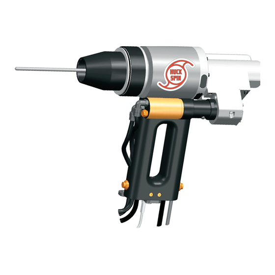
HS52 series Huck-Spin® Hydraulic Installation Tools (HK1076) System Matrix This instruction manual covers the installation tools listed below. Where components other than installation tools are mentioned, such as the Single Tool Controller and the Powerig®, refer to those individual instruction manuals. Where pictorial examples are given, the tool used is TOOLS: the HS52RM-1-1-0. -
Page 7: Specifications
HS52 series Huck-Spin® Hydraulic Installation Tools (HK1076) Specifications Hose Kits: Use only genuine HUCK Hose Kits rated at 10,000 psi (689.5 bar) working pressure. Automatic Hydraulic fluid: Hydraulic fluid shall meet DEXRON III, DEXRON VI, MERCON, Allison C-4 or equivalent Transmission Fluid (ATF) specifications. -
Page 8: Preparation For Use
HS52 series Huck-Spin® Hydraulic Installation Tools (HK1076) Preparation for Use WARNINGS: Use a Huck Powerig Hydraulic Unit, or equivalent, that has ® Huck recommends that a Huck Powerig been suitably prepared for operation. Check the PULL and ® be used to power Huck tools. (Only RETURN pressures and, if required, adjust to pressures given use the Powerig as indicated in its in Specifications section of this manual. -
Page 9: Maintenance
HS52 series Huck-Spin® Hydraulic Installation Tools (HK1076) Maintenance STANDARD SEALANTS, LUBRICANTS CAUTIONS: √ Use automatic transmission fluid DEXRON III or ® Consult the Material Safety Data Sheet (MSDS) equivalent. Fire resistant hydraulic fluid must be used before servicing tool. to comply with OSHA regulation 1926.302 paragraph Keep foreign matter out of the hydraulic system. -
Page 10: System Setup
HS52 series Huck-Spin® Hydraulic Installation Tools (HK1076) System Set-up Figure 4 To Plant Air Supply Plug power supply to 110 VAC Outlet 125727-2 Power Supply LEMO Connector Air Hoses Hydraulic Hoses Plug power supply to Powerig® 918 Powerig ® To primary power source Connect to Nose... -
Page 11: Pressure Settings
HS52 series Huck-Spin® Hydraulic Installation Tools (HK1076) Pressure Settings These pressures are for Low Swage Anvils, which can be identified by a step on the inside bore. Previous designs of anvils have a straight bore without any steps and will require higher pressures. These pressure values are only a starting point for setting the Powerig®. -
Page 12: Start-Up And Operation
HS52 series Huck-Spin® Hydraulic Installation Tools (HK1076) Start-up and Operation Figure 6 WARNING: During fastener installation, the tool will align itself with the axis of the bolt and will move toward the workpiece surface. To avoid personal injury, keep hands clear of all spaces between the tool and the workpiece, and between the workpieces. - Page 13 HS52 series Huck-Spin® Hydraulic Installation Tools (HK1076) Limit Switch Operation & Adjustment continued ... 2. Ensure that the air supply is disconnected at the manifold If the Limit Switch 2 illuminates before ½ turn from the and the electrical Powerig® cord is disconnected at the bottom, then turn the Disc in.
- Page 14 HS52 series Huck-Spin® Hydraulic Installation Tools (HK1076) Components Drawing HS52RM Models (continued) Figure 7b HS52RM-1-1-0 For Model: Part Number: 121453 - Hydraulic Assembly - components: See Figure 10 for more details 506815 121452 506068 509058 Rubber Plug (2) Piston & Seal Wiper Step Seal (2) 101577...
- Page 15 HS52 series Huck-Spin® Hydraulic Installation Tools (HK1076) Components Drawing - Drive Assembly 300292 Figure 8 Drive Assembly Part Number 124490-1 123741 500101 500047 External Drive Gear Screw, 10-32 x ½” Screw, 6-32 x ¼” (10) 500101 121429-2 506476 121474-1 Spacer Screw, 10-32 x ½”...
-
Page 16: Component Drawings
HS52 series Huck-Spin® Hydraulic Installation Tools (HK1076) Component Drawings Hydraulic, Piston, Switch, Actuator Disk and Rod Assemblies Figure 10 121453 Hydraulic Assembly 509057* Step Seal 506068* 121402 121400* 121452 Wiper Cylinder Cylinder End-Cap Piston & Seal Assembly (Figure 11) 124176 Wrenching Ring 508880 501163*... - Page 17 HS52 series Huck-Spin® Hydraulic Installation Tools (HK1076) Components Drawing - HS52 Models Figure 14a HS52-21-0-3-0 For Model: Part Number: 121453 - Hydraulic Assembly components: See Figure 10 for more details 124176 121452 509058 124240 501163 121400 Wrenching Ring Piston & Step Seal Switch Assembly Back-up Ring...
- Page 18 HS52 series Huck-Spin® Hydraulic Installation Tools (HK1076) Components Drawing - HSTM52 Models Figure 14b HSTM52-21-0 For Model: 121529 505588 502900 Drive Mounting Flange F.H.C.S. #8-32 x ½ L 101578 504646 101577 Retaining Ring Sleeve 124240 O-Ring Split Ring 121520 Switch Assembly 121406 Conical Spring Anvil Adapter...
- Page 19 HS52 series Huck-Spin® Hydraulic Installation Tools (HK1076) Components Drawing - HSTM52 Models Figure 14c HSTM52RM-1 HSTM52-21-0 For Models: 125775 Controller Manip. Asm 504300 F.H.C.S. ⁵⁄₁₆ -18 x ¾ Long 125462 Switch Holder 505588 125726 F.H.C.S. #8 -32 x ½ Long Assy, Manip.
-
Page 20: Disassembly Procedure
HS52 series Huck-Spin® Hydraulic Installation Tools (HK1076) Disassembly Procedure Before starting any maintenance, read and follow CAUTION: Always replace all Seals, Wipers, all precautions in the Safe Operation Section, O-rings and Back-up rings when disassembling including safely disconnecting the tool from the power the tool. - Page 21 HS52 series Huck-Spin® Hydraulic Installation Tools (HK1076) Disassembly Procedure (continued) DRIVE MOUNTING FLANGE Figure 18 Figures 18–20 Drive Assembly 13. Disconnect the air tubes from 506606 the fittings, 506485. (Fig.18) 2 ”, 14. With a hex key, remove Twin Tubing 500047 Remove both cap Screws that hold...
- Page 22 HS52 series Huck-Spin® Hydraulic Installation Tools (HK1076) Disassembly Procedure (continued) Figure 21 REAR MOTOR MODELS Remove the Figure 21 Trigger Assembly Loosen the 21. Use a Hex key/Allen wrench Switch Setscrew Switch Holder to remove the Trigger Switch Switch side Assembly from the motor.
- Page 23 HS52 series Huck-Spin® Hydraulic Installation Tools (HK1076) Disassembly Procedure (continued) INTERNAL DRIVE GEAR & BEARING Figure 26 31. With a soft dowel, tap/push Internal Drive Gear out 29. Using a hex key, remove the 2 screws holding of Housing. Actuator Disk Key in the Central Housing. 32.
-
Page 24: Assembly Procedure
HS52 series Huck-Spin® Hydraulic Installation Tools (HK1076) Assembly Procedure Refer to Maintenance. Figure 29 CYLINDER & PISTON ASSEMBLIES O-rings Inspect and clean out Seal grooves. CAUTION: Always replace all seals, wipers, O-rings, and Back-up rings when the tool is disassembled for any reason. Lubricate O-rings &... - Page 25 HS52 series Huck-Spin® Hydraulic Installation Tools (HK1076) Assembly Procedure (continued) NTERMEDIATE DRIVE GEAR & BEARING ASSY; DRIVE MOUNTING FLANGE Figure 32 19. Pack the bearings with bearing grease and press flush into the intermediate gear. 20. While pushing the shaft through the motor boss, install the intermediate gear and spacers, and tighten the shaft locking screw against the shaft.
- Page 26 HS52 series Huck-Spin® Hydraulic Installation Tools (HK1076) Assembly Procedure (continued) Figure 33 External Drive Gear Gear Cover with Apply bearing grease to teeth Drive Gear Bushing White Elbows and Muffler and lubricate shoulder and Spacer snapped in place Apply SLICTITE to threads ®...
-
Page 27: Troubleshooting
HS52 series Huck-Spin® Hydraulic Installation Tools (HK1076) Assembly Procedure (continued) ACTUATOR ROD ASSEMBLY; CONICAL SPRING; DRIVE SHAFT 43.. From the rear, slide actuator rod through the internal drive gear. NOTE: The “keyway” of the actuator disk must be aligned with the actuator disk key. 44. -
Page 28: Warranties
HS52 series Huck-Spin® Hydraulic Installation Tools (HK1076) Limited Warranties Limited Lifetime Warranty on BobTail® Tools: Huck shall not be liable for any loss or damage resulting Huck International, Inc. warrants to the original purchaser from delays or non-fulfillment of orders owing to strikes, that its BobTail®... - Page 29 HS52 series Huck-Spin® Hydraulic Installation Tools (HK1076) Notes...
- Page 30 Tel: +49-8251-8757-0 Fax: +33-1-34-33-97-77 HKSSalesDL@Howmet.com AICSalesDL@Howmet.com Huck provides technical assistance in the use 2022 Howmet Aerospace, Inc. © and application of Huck fasteners & tooling. NOTICE: This publication is only to be used for gen- Howmet Fastening Systems eral guidance in properties of the products shown...
Need help?
Do you have a question about the Huck-Spin HS52 Series and is the answer not in the manual?
Questions and answers