Table of Contents
Advertisement
Quick Links
Instruction Manual
2480 and 2481 series
Hydraulic Installation Tools
Makers of Huck
, Marson
®
Brand Fasteners, Tools & Accessories
, Recoil
®
®
Table of Contents
December 4, 2020
HK970
2
4-5
6
6
7
7
8
9
10
11-12
13
14-17
18
18
19
July 12, 2023
HK970
Advertisement
Table of Contents

Related Manuals for Howmet Aerospace HUCK 2480 Series


Summary of Contents for Howmet Aerospace HUCK 2480 Series
-
Page 1: Table Of Contents
Instruction Manual 2480 and 2481 series Hydraulic Installation Tools Table of Contents Declaration of Conformity Safety Instructions Description Specifications Principle of Operation Tool Setup Preparation for Use Operating Instructions Maintenance Disassembly Procedure 11-12 Assembly Procedure Components Drawings 14-17 Optional Equipment Sticker Locations Troubleshooting December 4, 2020... -
Page 2: Declaration Of Conformity
2480 & 2481 series Hydraulic Installation Tools (HK970) - Page 3 2480 & 2481 series Hydraulic Installation Tools (HK970) DANGER - IMPORTANT DO NOT EXCEED HOSE MINIMUM BEND RADIUS Failure to heed the warnings below could lead to a damaged hose, damaged tool, damaged property, personal injury, or death. • This high pressure hose is not to be used other than assembled in a genuine HUCK tool or hose assembly or used as a replacement for the hose of a genuine HUCK tool or hose assembly.
-
Page 4: Safety Instructions
2480 & 2481 series Hydraulic Installation Tools (HK970) Safety Instructions assembly before installing the next fastener. GLOSSARY OF TERMS AND SYMBOLS: 15. Check clearance between trigger and work piece to -Product complies with requirements set forth by ensure there is no pinch point when tool is activated. the relevant UK and European directives. - Page 5 2480 & 2481 series Hydraulic Installation Tools (HK970) Safety Instructions IV. REPETITIVE MOTION HAZARDS: 4. Operate and maintain tool as recommended in the 1. When using assembly power tool, the operator can instruction handbook to prevent an unnecessary experience discomfort in the hands, arms, shoulders, increase in the noise level.
-
Page 6: Description
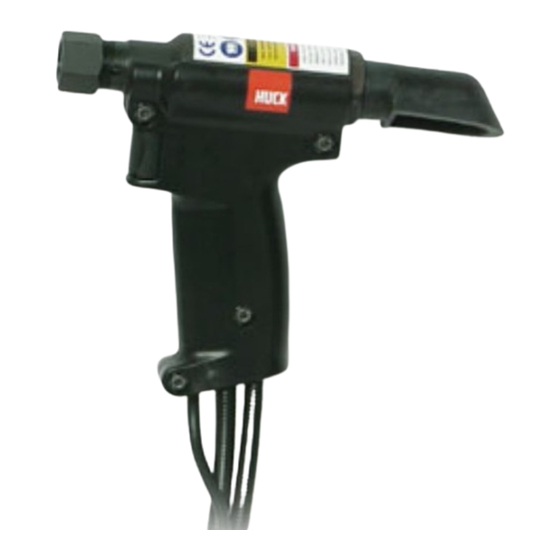
2480 & 2481 series Hydraulic Installation Tools (HK970) Description The 2480, A2480, and 2481 series, with appropriate nose The 2480 series has hoses that pass through the handle, assemblies, install a wide range of Huck blind fasteners and and 2481 has hoses attached to the top of the tool. HUCKBOLT®... -
Page 7: Principle Of Operation
2480 & 2481 series Hydraulic Installation Tools (HK970) A trigger controls the PULL and RETURN strokes. When the When the trigger is released at end of PULL stroke when trigger is pressed, hydraulic pressure is directed to PULL fastener is installed, the pressure is directed to RETURN side side of the piston, and fastener installation begins. -
Page 8: Preparation For Use
2480 & 2481 series Hydraulic Installation Tools (HK970) Preparation for Use 3. First, turn hydraulic unit to OFF; then disconnect power WARNINGS: Correct PULL and RETURN pressures supply from hydraulic unit. Disconnect trigger control are required for operator safety and for system from hydraulic unit. -
Page 9: Operating Instructions
2480 & 2481 series Hydraulic Installation Tools (HK970) Operating Instructions This tool is shipped with an attached regulator and a 1/4” inside diameter air hose (Huck p/n 115436), with a plastic plug in the air inlet connector. An air supply capable of 6.3 CFM at a pressure greater than 10 psi greater than the installed regulator set point (Figure 16) must be available. -
Page 10: Maintenance
2480 & 2481 series Hydraulic Installation Tools (HK970) Maintenance SERVICE PARTS KIT CAUTION: Do not use TEFLON tape on pipe ® Service parts kit 2480KIT contains perishable parts for both threads. Pipe threads may cause tape to shred the 2480 and 2481 family of tools. For convenience, and resulting in tool malfunction. -
Page 11: Disassembly Procedure
2480 & 2481 series Hydraulic Installation Tools (HK970) Disassembly Procedure 7. Electric Trigger Models: Disassemble switch and cord The following procedure is for complete disassembly. Disassemble only subassemblies necessary to check assembly as instructed in Figure 7. and replace damaged seals, wipers, back-up rings and Air Trigger Models: Disassemble air trigger and hose components. - Page 12 2480 & 2481 series Hydraulic Installation Tools (HK970) Disassembly Procedure DISASSEMBLE CYLINDER ASSEMBLY unloading valve, and end cap/rear gland out through the rear of the tool. (Figure 9) 1. Place spacer over threaded end of piston; then thread piston assembly tool onto the piston. If the cylinder 5.
-
Page 13: Assembly Procedure
2480 & 2481 series Hydraulic Installation Tools (HK970) Assembly Procedure Clean out O-ring grooves and reinstall perishable parts (seals, Figure 10 GLANDS, PISTON, AND VALVE ASSEMBLY etc.) using service kit 2480KIT. NOTE: The small inner ring insert of polyseals must remain positioned as shown. If it is forced out of seal body, it may be pinched against gland inner edge. -
Page 14: Components Drawings
2480 & 2481 series Hydraulic Installation Tools (HK970) 2480 series Components Figure 11 Piston Assembly (Note 1) 128471 Front Gland Assembly See Table below for part number: 128473 Rear Gland Assembly (not sold separately) Piston (not sold separately) Front Gland (not sold separately) Rear Gland 500816 O-Ring... - Page 15 2480 & 2481 series Hydraulic Installation Tools (HK970) 2481 series Components Figure 12 See Figure 13 for Hoses, and Cord part numbers Power Cord Hydraulic Hose with Hydraulic Hose with male connector end female connector end 124883 Piston Assembly (2481) 124875-2 Piston Assembly (2481L-1) See Note 1 124871 Front Gland Assembly...
- Page 16 2480 & 2481 series Hydraulic Installation Tools (HK970) Hydraulic Hoses and Electric Trigger and Cord Figure 13 Tool Hose Number Hose Control Cord Handle Number Length Assembly Number 2480 HPHX12-AA10 12 ft. 124880 13 ft. 2480-2 HPHX02-AA10 2 ft. 124880-3 3 ft.
- Page 17 2480 & 2481 series Hydraulic Installation Tools (HK970) Air Hoses and Trigger and Cord Figure 14 Tool Hose Number Hose Control Cord Handle Number Length Assembly Number A2480 124881-1 12 ft. 124889 13 ft. A2480-6 124881-2 6 ft. 124889-1 6.5 ft. A2480-30 HPHX30-AA10 30 ft.
-
Page 18: Optional Equipment
2480 & 2481 series Hydraulic Installation Tools (HK970) 2480 & 2481 series Hydraulic Installation Tools (HK970) Optional Equipment Optional Equipment Pressure Gauge T-124833CE Hose and Cord Kits Hose Length Part No. Pressure Gauge T-124833CE Hose and Cord Kits Hose Length Part No. (Contains control cord - 6 ft 118309-6... -
Page 19: Troubleshooting
2480 & 2481 series Hydraulic Installation Tools (HK970) Troubleshooting Always check the simplest possible cause of a malfunction first. For example, a loose or disconnected trigger line. Then proceed logically, eliminating each possible cause until the defective part is located. Where possible, substitute known good parts for suspected defective parts. - Page 20 2480 & 2481 series Hydraulic Installation Tools (HK970) Notes...
- Page 21 2480 & 2481 series Hydraulic Installation Tools (HK970) Limited Warranties Limited Lifetime Warranty on BobTail® Tools: Tooling, Part(s) and Other Items not manufactured by Huck: Huck International, Inc. warrants to the original purchaser that its BobTail® installation tools manufactured after HUCK makes no warranty with respect to the tooling, 12/1/2016 shall be free from defects in materials and part(s), or other items manufactured by third parties.
- Page 22 HKSSalesDL@howmet.com Huck provides technical assistance regarding the use and application of © 2021 Howmet Aerospace, Inc. Huck fasteners and tooling. NOTICE: The ISO 9001-2015 Howmet Fastening Systems information contained in this publication CERTIFIED is only for general guidance with regard...
Need help?
Do you have a question about the HUCK 2480 Series and is the answer not in the manual?
Questions and answers