Advertisement
Quick Links
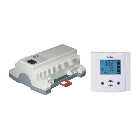
TLR-D5P
Intelligent Package Unit Controller, Base & Terminal
Features
•
Temperature control for 2-pipe or 4-pipe package units (fan supported dual heating or cooling stages with
reversing valve)
•
Temperature control for 2-pipe package units (fan supported dual heating or cooling stages)
•
Temperature control for 4-pipe package units (fan supported heating and cooling 1. stage + optional 2 stage
heating or cooling)
•
Relays switching for outputs each up to 10(6)A
•
Large temperature range from
–20°C to 70°C (-4°F to 158°F).
•
Control for heating, cooling and fan only operation
•
Adjustable start and stop delays to protect compressors and switching elements
•
Cost saving option with Economy functionality and set point limitations
•
External sensor or open contact for remote control, external heat – cool change or auto-changeover on supply
or outdoor temperature with selectable activation limits
•
Password protected programmable user and control parameters
Setpoint range limitation
o
Access control for setpoints, fan speeds and mode change
o
Access control for heat/cool change and time programs
o
Select your display contents
o
Selectable behavior after return from power failure
o
•
Temperature display in Celsius or Fahrenheit
Deluxe Version:
Clock and time schedule functions with special options for schools and universities
o
Clock keeps running for 48h in case of power failure
o
Display with blue backlight
o
Infrared remote controller option:
o
With special features for Boost and delayed switching on or off
Applications
•
Air Only Systems: fan supported heating or/and cooling stages e.g. compressors, electric heaters.
•
Air/Water Systems: Induction units, fan supported dual coil units for 2- and 4-pipe systems
General Description
The TLR-D5P is a stand-alone electronic package unit controller with one control loop. The TLR-D5P includes 1 internal
NTC temperature sensor, one open/contact or external NTC temperature input and five binary outputs (Relays).
A detailed adaptation to local conditions is possible with the use of a simple configuration routine. The TLR-D5P can be
configured using the standard operation terminal. No special tools or software is required.
The TLR-D5P has been specifically developed to switch larger fans with switching power of up to 10 (6) A.
Doc: 70-00-0096 V2.2 Date: 20090203
TLR-D5P Engineering Manual
©2008 Vector Controls
Page 1
Advertisement

Related Manuals for Vector TLR-D5P


Summary of Contents for Vector TLR-D5P
- Page 1 NTC temperature sensor, one open/contact or external NTC temperature input and five binary outputs (Relays). A detailed adaptation to local conditions is possible with the use of a simple configuration routine. The TLR-D5P can be configured using the standard operation terminal. No special tools or software is required.
- Page 2 TLR-D5P Engineering Manual Name - U - 2 4 Deluxe version Power supply voltage Fits on 2” x 4” connection box Package Unit Control Mode Number of binary outputs DO = 5 Digital communication base – terminal Series (TLR) Ordering...
- Page 3 TLR-D5P Engineering Manual Technical specifications Power Supply Operating Voltage TLR-D5P-24 24 V AC ± 10 %, 50…60 Hz TLR-D5P-230 230 V AC ± 10 %, 50…60 Hz Power Consumption TLR-D5P-24 Max. 3 VA TLR-D5P-230 Max. 5 VA Electrical Connection Terminal Connectors, wire 0.34…2.5 mm (AWG 24…12)
- Page 4 TLR-D5P Engineering Manual Selection of actuators and sensors Temperature Sensors: Use only our approved NTC sensors to achieve maximum accuracy. Recommended is SDB-Tn10-20 as Duct sensor, SRA-Tn10 as Room sensor and SDB-Tn10-20 with AMI-S10 as immersion sensor. Binary auxiliary devices: Compressors, heat stages on/off valves, etc.
- Page 5 TLR-D5P Engineering Manual Mechanical design and installation The unit consists of two parts: The base unit and the terminal. Installation base The housing of the TLR base unit is a compact enclosure. The controller may be mounted in any orientation by surface mounting on a wall or in a cabinet with two screws or on a 35mm DIN rail.
- Page 6 TLR-D5P Engineering Manual Display and Operation The operation terminal uses an LCD display and four operation buttons. Legend: 4-digit display of current value, time, control parameter or setpoint Unit of displayed value, °C, °F, % or none Indication of fan speeds...
- Page 7 Clock Operation and Time Schedules (Deluxe Version) TLR-D5P-D contains a real time clock. Up to 16 mode changes (not defined, Off, Economy, Comfort, University mode) based on weekdays and time may be programmed. See chapter operation on how to program switch times.
- Page 8 TLR-D5P Engineering Manual Operation of the terminal unit Switching ON The unit is switched on by pressing the POWER button. It will start up in comfort mode. Changing between COMFORT and ECONOMY Pressing the POWER button for less than 2 seconds toggles between ECONOMY and COMFORT modes. Economy mode may be disabled with UP06.
- Page 9 Clock settings The remote controller contains a daytime clock. The receiving TLR-D5P controller will adopt the OPR-1’s own clock whenever it received a command from it. In order to set the clock in the OPR-1, press HOUR and MINUTE button together until the clock starts blinking. Then set the correct time with the HOUR and MINUTE buttons.
- Page 10 TLR-D5P Engineering Manual Setting of parameters The TLR-D5P is an intelligent controller and can be adapted to fit perfectly into your application. The control operation is defined by parameters. The parameters are set during operation by using the standard operation terminal.
- Page 11 TLR-D5P Engineering Manual Control Functions The controller is designed to control package units with up to two heating or cooling stages and one support fan. The unit may be controlled to run in fan only mode or automatic. In automatic mode, the controller will change heating or cooling stages according to the temperature difference of room temperature and setpoint.
- Page 12 TLR-D5P Engineering Manual Switching Delays Delay switching off: Using this delay will prevent rapid switching of the compressor. After switching on, the compressor will only switch off after the delay switching off time is expired. The selectable range is 0…255 seconds.
- Page 13 Frost protection should be disabled for cooling only systems. (Per default on TLR-D41-W01) Temperature input Accuracy in Kelvin, The TLR-D5P includes an NTC-based passive temperature sensor. A Temperature Input sensor of the same type can be connected as alternative control input or as input for additional functions.
- Page 14 Set user settings (UP) Configuration parameters for firmware version 2.2 The TLR-D5P can be adapted to a wide variety of applications. The adaptation is done through parameters. The parameters can be changed on the unit without the need of additional equipment.
- Page 15 TLR-D5P Engineering Manual Control Parameters (Access Code: 241) Warning! Only experts should change these settings! See user parameters for login procedure. Setpoint limitations Parameter Description Range Default CP 00 Minimum setpoint limit in Heating mode -40…60°C (160°F) 16°C (61°F) CP 01 Maximum setpoint limit in Heating mode -40…60°C (160°F)
Need help?
Do you have a question about the TLR-D5P and is the answer not in the manual?
Questions and answers