Table of Contents
Advertisement
Quick Links
TCI-C series cabinet mounted universal controller
Applications
Heat exchangers
Zoning
Boilers
General
TCI-C11: 1 independent control loop, 2 universal inputs (analog/binary/temp), 2 binary outputs, 1 analog output
TCI-C22: 2 independent control loops, 4 universal inputs, 2 binary outputs, 2 analog output2.
Flexible application configuration is made with a parameter-setting routine using the standard operation terminal.
Name
- C
T
C
I
2
Ordering
Model
Order code
TCI-C11-0
40-11 0060
TCI-C13-0
40-11 0064
TCI-C22-0
40-11 0062
TCI-C14-0
40-11 0071
TCI-C15-0
40-11 0067
TCI-C24-0
40-11 0070
TCI-C25-0
40-11 0068
Temperature sensors: Use Vector Controls NTC or PT1000/NI1000 sensors to achieve maximum accuracy: SDB-Tn10-
20 (duct), SRA-Tn10 (room), SDB-Tn10-20 + AMI-S10 as immersion sensor for NTC (used with TCI-C11, TCI-C13 and
TCI-C22). SDB-Tp2-20 (duct), SRA-Tp2 (room), SDB-Tp2-20+AMI-S10 (immersion), SOD-Tp2 (outdoor) for PT1000 used
with TCI-Cx4 and TCI-Cx5.
Actuators: Choose modulating actuators with an input signal type of 0-10 V DC or 4-20 mA (min. and max. signal
limitations may be set with parameters. 3-pointpoint actuators with constant running time are recommended.
Binary auxiliary devices (e.g. pumps, fans, on/off valves, humidifiers, etc.): Do not directly connect devices that
exceed specified limits in technical specifications – observe startup current on inductive loads.
Doc: 70-00-0123, V1.3, Date: 20170131
Subject to alteration
Features
TCI-C22 also includes
VAV
Air handlers
Fan, pump control
-
2
0
Supply voltage: 0 - 24VAC
In/outputs: see table below
Control loops: 1 - 1 control loop, 2 - 2 control loops
Mounting: C - cabinet
Series: TCI
Power
Option
24 VAC
Standard
24 VAC
Standard
24 VAC
Schedules
24 VAC
Standard
24 VAC
Standard
24 VAC
Schedules
24 VAC
Schedules
Universal PID and/or binary control for any analog
input/output signal and range
Multiple auxiliary functions: heat-cool auto changeover,
automatic enable, set point compensation
Differential, averaging, min. and max. functions
Cascading of control loops (-C22 type)
Alarm monitoring of low and high limits on all inputs
Programmable reaction in case of alarm
Feedback function for inputs and set points
Functions for dehumidifying, set point shift, cascade
control
Password protected programmable user and control
parameters
Power cap protected real-time clock with 48 hr power
backup
7-day programmable schedules, with options including
change of set points and direct position of manual
outputs
Blue backlight
Humidifiers
Dehumidifiers
Ventilation
Loop
Input
Temp
1
2
NTC
1
2
NTC
2
4
NTC
1
2
PT/NI1000
1
2
PT/NI1000
2
4
PT/NI1000
2
4
PT/NI1000
© Vector Controls GmbH, Switzerland
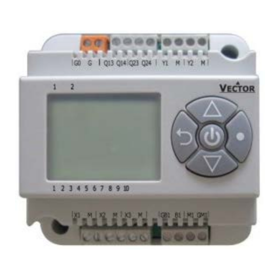
TCI-C Universal Controller
O
VERVIEW
Radiant heating
Radiant cooling
Pressurization
Binary
Analog
output
output
2 relays
1
2 TRIAC
1
2 relays
2
2 relays
1
2 TRIAC
1
2 relays
2
2 TRIAC
2
Page 1
Advertisement
Table of Contents

Related Manuals for Vector TCI-C Series


Summary of Contents for Vector TCI-C Series
- Page 1 PT/NI1000 2 TRIAC Temperature sensors: Use Vector Controls NTC or PT1000/NI1000 sensors to achieve maximum accuracy: SDB-Tn10- 20 (duct), SRA-Tn10 (room), SDB-Tn10-20 + AMI-S10 as immersion sensor for NTC (used with TCI-C11, TCI-C13 and TCI-C22). SDB-Tp2-20 (duct), SRA-Tp2 (room), SDB-Tp2-20+AMI-S10 (immersion), SOD-Tp2 (outdoor) for PT1000 used with TCI-Cx4 and TCI-Cx5.
-
Page 2: Technical Specifications
60 x 93 x 115 mm (2.4 x 3.7 x 4.5) inch Weight (including package) TCI-C11, TCI-C14: 280g (9.9oz) TCI-C13, TCI-C15, TCI-C22, TCI-C24: 295 g (10.4 oz) TCI-C25: 305 g (10.8 oz) Doc: 70-00-0123, V1.3, Date: 20170131 © Vector Controls GmbH, Switzerland Page 2 Subject to alteration... -
Page 3: Terminal Description
Supplying voltages above AC 24 V to low voltage connections may damage the controller or other devices. Connection to voltages exceeding 42 V endangers personnel safety. Doc: 70-00-0123, V1.3, Date: 20170131 © Vector Controls GmbH, Switzerland Page 3 Subject to alteration... -
Page 4: Display And Operation
Verify input connections, jumper settings and parameter settings for the input involved. Err3: A function refers to a disabled input. Disable the function or enable the input. Err4: Internal failure. Product must be replaced. Doc: 70-00-0123, V1.3, Date: 20170131 © Vector Controls GmbH, Switzerland Page 4 Subject to alteration... -
Page 5: Clock Operation
Available actions blink as you scroll through them, press OPTION to select one: Pr01 Characteristics of action (e.g. 0–100% for A1) appear (4 bar indicates step 4 complete) 08:00 Press UP/DOWN to select, OPTION to complete Doc: 70-00-0123, V1.3, Date: 20170131 © Vector Controls GmbH, Switzerland Page 5 Subject to alteration... -
Page 6: Setup And Configuration
Press the POWER to leave the menu. The unit will return to normal operation if no button is pressed for more than 5 minutes. Doc: 70-00-0123, V1.3, Date: 20170131 © Vector Controls GmbH, Switzerland Page 6 Subject to alteration... -
Page 7: User Configuration
1–255= Delay for controller to go back to the scheduled Energy Hold OFF, 0–255 Min 60 (min.) (TCI-C2x) ECONOMY, or COMFORT operation mode if the operation mode is changed manually. Doc: 70-00-0123, V1.3, Date: 20170131 © Vector Controls GmbH, Switzerland Page 7 Subject to alteration... -
Page 8: Input Configuration
UI2 in – UI1 = UI2 out. It is possible to have multiple differentials on one controller. It is not possible to reverse the subtraction to UI1-UI2. Doc: 70-00-0123, V1.3, Date: 20170131 © Vector Controls GmbH, Switzerland Page 8 Subject to alteration... -
Page 9: Control Loop Configuration
Commonly this is used for humidity control to avoid condensation on outside walls or windows in very cold weather. Doc: 70-00-0123, V1.3, Date: 20170131 © Vector Controls GmbH, Switzerland Page 9 Subject to alteration... - Page 10 Dead zone h/c set points Offset heating/reverse Offset cooling/direct Set point heating/reverse T [°C, F] Set point cooling/direct U [V, mA] PI sequence heating/reverse PI sequence cooling/direct Doc: 70-00-0123, V1.3, Date: 20170131 © Vector Controls GmbH, Switzerland Page 10 Subject to alteration...
- Page 11 Input signal Dead zone Offset heating/reverse Offset cooling/direct Set point heating/reverse Set point cooling/direct Binary sequences cooling/direct T [°C, F] U [V, mA] Binary sequences heating/reverse Doc: 70-00-0123, V1.3, Date: 20170131 © Vector Controls GmbH, Switzerland Page 11 Subject to alteration...
-
Page 12: Output Configuration
1A03. As the system moves into heating mode, heating airflow increases until it reaches the maximum heating output (1A04), typically 30 to 50% of maximum cooling airflow. Doc: 70-00-0123, V1.3, Date: 20170131 © Vector Controls GmbH, Switzerland Page 12 Subject to alteration... - Page 13 State functions (1d01=5) activate the output based on certain conditions with or without a demand for heating or cooling, in either comfort or standby mode. In Energy Hold OFF mode (EHO) the output will be off. Doc: 70-00-0123, V1.3, Date: 20170131 © Vector Controls GmbH, Switzerland Page 13 Subject to alteration...
- Page 14 100 seconds as the lifetime of the relays will be shortened with frequent switching. For PWM applications requiring cycle times below 100 seconds we recommend using TCI-C13 with TRIAC outputs. Doc: 70-00-0123, V1.3, Date: 20170131 © Vector Controls GmbH, Switzerland Page 14 Subject to alteration...
-
Page 15: Auxiliary Functions
Activate comfort/economy changeover with loop configuration parameter(L07). Limit 2 > Limit 1 Limit 1 > Limit 2 Comfort Comfort Mode Mode Standby Standby Limit Limit Limit Limit Input Input Doc: 70-00-0123, V1.3, Date: 20170131 © Vector Controls GmbH, Switzerland Page 15 Subject to alteration... -
Page 16: Aux Functions
Limit 1 > Limit 2 Enable Enable Mode Mode Disable Disable Limit Limit Limit Limit Input Input Enable Mode Mode Enable Disable Disable Limit Limit Limit Limit Input Input Doc: 70-00-0123, V1.3, Date: 20170131 © Vector Controls GmbH, Switzerland Page 16 Subject to alteration... - Page 17 Limit 1, cool to heat at Limit 2. For binary open/close contact, open is a high value (100%), closed is a low value (0%). Limit 2 > Limit 1 Limit 1 > Limit 2 Heat Heat Mode Mode Cool Cool Limit Limit Limit Limit Input Input Doc: 70-00-0123, V1.3, Date: 20170131 © Vector Controls GmbH, Switzerland Page 17 Subject to alteration...
Need help?
Do you have a question about the TCI-C Series and is the answer not in the manual?
Questions and answers