Advertisement
Quick Links
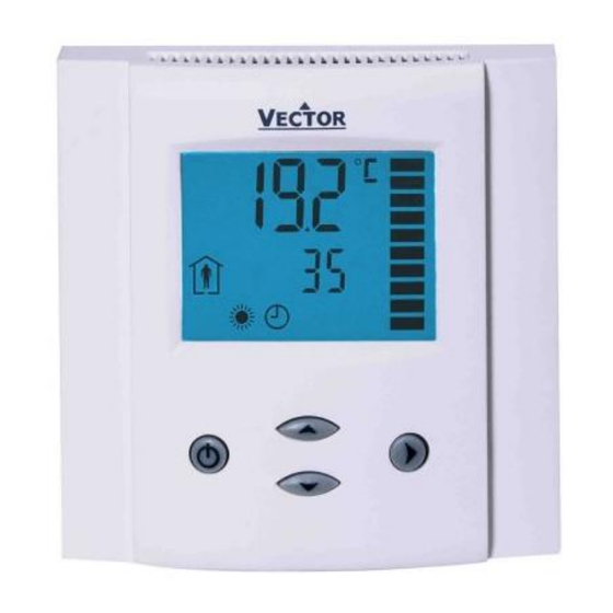
TLC3-FCM-R2
Programmable PI Fan Coil controller
Features
•
Proven PI controls algorithm reduces room temperature fluctuations
and energy consumption
•
Low power energy consumption: < 0.5 W per unit
•
Temperature control for 2- and 4-pipe fan coil systems.
•
Automatic fan control for EC fans.
•
Cost saving option with Economy functionality and set point
limitations
•
Control for modulating heating, cooling and fan only operation modes
•
Password protected programmable user and control parameters
Setpoint range limitation
o
Access control for setpoints, fan speeds and mode change
o
Access control for heat/cool change and time programs
o
Select your display contents
o
Selectable behavior after return from power failure
o
•
Temperature display in Celsius or Fahrenheit
Deluxe Version:
•
Clock and time schedule functions with power failure protection
•
Blue backlight for LCD
•
Infrared remote controller option:
With special features for Boost and delayed switching on or off
Applications
•
Air Only Systems:
Constant or Variable Air Volume systems with three stage fans for single or dual duct systems
o
•
Air/Water Systems:
Fan Coil units for 2-pipe or 4-pipe systems
o
radiator control, chilled ceiling
o
•
Simple individual room control for hotel rooms, meeting rooms, etc.
•
PI-Control of up to 2 modulating valves for heating and cooling
General Description
The TLC3-FCM-R2-T is a stand-alone electronic fan coil controller with one control loop. The TLC3-FCM-R2-T is
designed for EC fan coil systems and features 1 internal NTC temperature sensor, one external passive input for
temperature or open contact, two binary outputs (Relays) and one analog output (0-10VDC) for fan control.
The TLC3-FCM2-R2 is a stand-alone electronic fan coil controller with one control loop. The TLC3-FCM2-R2 is
designed for EC fan coil systems and features 1 internal NTC temperature sensor, two binary outputs and two analog
outputs (0-10VDC) one for fan control and one for a heating or cooling valve.
A detailed parameterization is possible with the use of a simple configuration routine. The TLC3-FCM-R2 can be
configured using the standard operation terminal. No special tools or software is required.
Ordering
Item Name
TLC3-FCM-R2-T-230
TLC3-FCM-R2-T-D-230
TLC3-FCM2-R2-230
TLC3-FCM2-R2-D-230
Selection of sensors
Use only our approved NTC sensors to achieve maximum accuracy. Recommended is SDBTn10-15 as Duct sensor,
SRA-Tn10 as Room sensor and SDB-Tn10-15+AMI-10 as immersion sensor.
Selection of fans
Do not directly connect devices that exceed 2A. Observe startup current on inductive loads! Do not connect more than
one fan coil unit to one controller.
Modulating Actuators:
Choose actuators with an input signal type of 0-10V DC or 2-10V DC. Observe maximal signal current of 1mA!
Doc: 70-00-0891, V1.0 Date: 20220613
Subject to alteration
Item code
Variant
40-10 0278
Standard
40-10 0249
Deluxe
40-10 0279
Standard
40-10 0251
Deluxe
© Vector Controls GmbH, Switzerland
TLC3-FCM-R2 Engineering Manual
Power
Features
Fan coil controller with:
1 TI int
230VAC
1 external input (NTC)
2 DO (Relay)
1 AO (0-10VDC)
1 TI int
230VAC
2 DO (Relay)
2 AO (0-10VDC)
Page 1-12
Advertisement

Related Manuals for Vector TLC3-FCM-R2


Summary of Contents for Vector TLC3-FCM-R2
- Page 1 (0-10VDC) one for fan control and one for a heating or cooling valve. A detailed parameterization is possible with the use of a simple configuration routine. The TLC3-FCM-R2 can be configured using the standard operation terminal. No special tools or software is required.
- Page 2 60 x 50 x 32mm (2.4 x 2.0 x 1.26 in.) Distance for mounting screws: Horizontal and vertical: 45 to 63mm (1.8 to 2.5 in.) Doc: 70-00-0891, V1.0 Date: 20220613 © Vector Controls GmbH, Switzerland Page 2-12 Subject to alteration...
- Page 3 This screw is located on the front lower side of the unit. There is no need to tighten the screw too much. Wiring Diagram TLC3-FCM2-R2-230 Doc: 70-00-0891, V1.0 Date: 20220613 © Vector Controls GmbH, Switzerland Page 3-12 Subject to alteration...
- Page 4 Heating or cooling based on FC27 Analog output 0…10 VDC TLC3-FCM-R2-T: Signal common: RT/DI Input NTC 10kΩ @ 25°C (77°F) or open contact to GND Analog output 0…10 VDC Doc: 70-00-0891, V1.0 Date: 20220613 © Vector Controls GmbH, Switzerland Page 4-12 Subject to alteration...
- Page 5 The output is switched off. Verify parameter settings and wiring. Steady: Frost protection is active. Blinking: Frost protection activated in the past and is now inactive. Confirm with OPTION key. Doc: 70-00-0891, V1.0 Date: 20220613 © Vector Controls GmbH, Switzerland Page 5-12 Subject to alteration...
- Page 6 A blinking clock indicates that the time needs to be set. Time programs will not operate if the time is not defined. ➔ See chapter operation, advanced settings for instructions on how to set the time. Access to time schedules may be disabled with UP-04 ➔ Doc: 70-00-0891, V1.0 Date: 20220613 © Vector Controls GmbH, Switzerland Page 6-12 Subject to alteration...
- Page 7 Repeatedly pressing the mode button may activate the following operation modes: HEAT, COOL and FAN ONLY. The mode change may be disabled using the UP parameters. Note: The remote controller is currently only available in °C mode. Doc: 70-00-0891, V1.0 Date: 20220613 © Vector Controls GmbH, Switzerland Page 7-12 Subject to alteration...
- Page 8 Setting of user parameters The TLC3-FCM-R2 is an intelligent controller and can be adapted to fit perfectly into your fan coil application. The control operation is defined by parameters. The parameters are set during operation by using the standard operation terminal.
- Page 9 Depending on the room size and heating / cooling equipment used a value between 0.1 and 1.5 should be sufficient. Below are suggested values: Heating: K : 0.1-0.4 Cooling: K : 0.1-0.6 Doc: 70-00-0891, V1.0 Date: 20220613 © Vector Controls GmbH, Switzerland Page 9-12 Subject to alteration...
- Page 10 In Auto Mode the fan is controlled by the PI signal. In Manual mode FC23…FC25 define the fan speed. With FC19…FC20 the fan speed may be limited during heating - or with FC21...FC22 in cooling mode. Configuration of inputs (only for TLC3-FCM-R2-T) Parameter...
- Page 11 TLC3-FCM-R2 Engineering Manual Empty page. Doc: 70-00-0891, V1.0 Date: 20220613 © Vector Controls GmbH, Switzerland Page 11-12 Subject to alteration...
- Page 12 TLC3-FCM-R2 Engineering Manual Smart Sensors and Controls Made Easy! Quality - Innovation – Partnership Vector Controls GmbH Switzerland info@vectorcontrols.com www.vectorcontrols.com/ Doc: 70-00-0891, V1.0 Date: 20220613 © Vector Controls GmbH, Switzerland Page 12-12 Subject to alteration...
Need help?
Do you have a question about the TLC3-FCM-R2 and is the answer not in the manual?
Questions and answers