Table of Contents
Advertisement
Quick Links
V
ECTOR
Fan coil controller with Modbus RTU
Document sections
General Description
Technical Specifications
Operation
Setting up the controller
Configuration (parameter options)
Runtime Data
Additional Information
Doc: 70-00-0958A V1.0, 20221102
Subject to change without notice
TRA-F22x-A
© Vector Controls GmbH, Switzerland
www.vectorcontrols.com
Chapter
Page
1
2
2
4
3
6
4
12
5
13
6
31
7
33
TRA-F22x-A
Page 1-34
Advertisement
Chapters
Table of Contents

Related Manuals for Vector TRA-F22 A Series


Summary of Contents for Vector TRA-F22 A Series
- Page 1 Fan coil controller with Modbus RTU Document sections Chapter Page General Description Technical Specifications Operation Setting up the controller Configuration (parameter options) Runtime Data Additional Information Doc: 70-00-0958A V1.0, 20221102 © Vector Controls GmbH, Switzerland Page 1-34 Subject to change without notice www.vectorcontrols.com...
- Page 2 Ignoring specifications and local regulations may cause equipment damage and endangers life and property. Tampering with the device and misapplication will void the warranty. Doc: 70-00-0958A V1.0, 20221102 © Vector Controls GmbH, Switzerland Page 2-34 Subject to change without notice...
- Page 3 SOD-Tn10-1 40-200108 Outdoor temperature sensor (2.5 x 2.5 x 1.4 inch) Additional sensors and accessories can be found on the Vector Controls home page www.vectorcontrols.com. Doc: 70-00-0958A V1.0, 20221102 © Vector Controls GmbH, Switzerland Page 3-34 Subject to change without notice...
- Page 4 Declaration of Information on the conformity of our products can be found on our website Conformity www.vectorcontrols.com on the corresponding product page under "Downloads". Doc: 70-00-0958A V1.0, 20221102 © Vector Controls GmbH, Switzerland Page 4-34 Subject to change without notice www.vectorcontrols.com...
- Page 5 The wiring for the different predefined TRA-F22x-A applications can be found in chapter 5.6.3, page 19. A typical connection of the TRA-F22x-A is shown below: Doc: 70-00-0958A V1.0, 20221102 © Vector Controls GmbH, Switzerland Page 5-34 Subject to change without notice...
-
Page 6: Table Of Contents
Change fan mode (auto mode or fan speed) Menu navigation: Enter menu point (Enter, Save) Parameter change: Save parameter Long press: Display external input status Doc: 70-00-0958A V1.0, 20221102 © Vector Controls GmbH, Switzerland Page 6-34 Subject to change without notice www.vectorcontrols.com... -
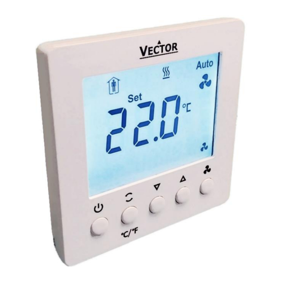
Page 7: Lcd Display
When the cooling symbol is blinking the cooling valve is turned on. Fan Only The bars between the fan symbols show the fan speed. Doc: 70-00-0958A V1.0, 20221102 © Vector Controls GmbH, Switzerland Page 7-34 Subject to change without notice www.vectorcontrols.com... -
Page 8: Large And Small Digits
The switching differential or proportional band is 2°C for heating mode and 1°C for cooling mode (configurable via parameters P400 and P401). The default integral time is 5 minutes (adjustable via parameter P402 with 300 seconds as default value). Doc: 70-00-0958A V1.0, 20221102 © Vector Controls GmbH, Switzerland Page 8-34 Subject to change without notice www.vectorcontrols.com... -
Page 9: Controller Operation
(according to the Operating Mode Comfort, Economy or manual setting), by controlling the fan speeds and the cooling valve. Doc: 70-00-0958A V1.0, 20221102 © Vector Controls GmbH, Switzerland Page 9-34 Subject to change without notice... -
Page 10: Temperature Control
(format: 1r0, means version 1 revision 0). For TRA-F221-A, the Modbus address of the controller is shown for two seconds. Display test Software version (example) Modbus address (example) Doc: 70-00-0958A V1.0, 20221102 © Vector Controls GmbH, Switzerland Page 10-34 Subject to change without notice www.vectorcontrols.com... -
Page 11: Power Failure
Press the Operating ( ) or Controlling ( ) Mode button to leave the menu. After one minute the input menu is left automatically. Doc: 70-00-0958A V1.0, 20221102 © Vector Controls GmbH, Switzerland Page 11-34 Subject to change without notice www.vectorcontrols.com... - Page 12 Selection of actuators and sensors Temperature sensors: Use Vector Controls NTC sensors to achieve maximum accuracy, see ordering list in chapter 1.3, page 3. Binary auxiliary devices (e.g. fans, on/off valves, etc.): Do not directly connect devices that exceed specified limits in technical specifications – observe startup current on inductive loads.
-
Page 13: Content Of Chapter 5.1 Parameter Usage
The multiplier is only used for Modbus data access. On the user interface, the values are displayed in normal resolution. Parameter with values below 0 (zero) are given as signed integer values. Doc: 70-00-0958A V1.0, 20221102 © Vector Controls GmbH, Switzerland Page 13-34 Subject to change without notice... -
Page 14: Configuration (Parameter Options)
Allow changing of parameter settings through P005 communication 1 = Allowed 0 = No offset P006 Modbus address PLC style 1 = PLC address style (+1 address offset) Doc: 70-00-0958A V1.0, 20221102 © Vector Controls GmbH, Switzerland Page 14-34 Subject to change without notice www.vectorcontrols.com... -
Page 15: Operating Options
1 = Enable (parameter can be changed from user interface) 0 = Protection mode (OFF) P110 State after power failure 1 = Comfort mode (ON) 2 = State before power failure Doc: 70-00-0958A V1.0, 20221102 © Vector Controls GmbH, Switzerland Page 15-34 Subject to change without notice www.vectorcontrols.com... -
Page 16: Quick System And Output Configuration (Application Specific)
Application modes: Wiring diagrams of outputs An overview of the of the application specific output wiring diagrams can be found in chapter 5.6.3, page 19. Doc: 70-00-0958A V1.0, 20221102 © Vector Controls GmbH, Switzerland Page 16-34 Subject to change without notice... -
Page 17: System And Output Configuration
P203 = 0/1: DO01 and DO02 are used as valve outputs, AO01 is used as the 0-10V fan output. P203 = 2/3: DO01 to DO03 are used as 3-stage fan outputs, AO01 and AO02 are used as valve outputs. Doc: 70-00-0958A V1.0, 20221102 © Vector Controls GmbH, Switzerland Page 17-34 Subject to change without notice... -
Page 18: Application Modes: Valve Control Diagrams
Heated/chilled ceiling NTC / DI 2-pipe system auto heat/cool changeover 4-pipe system T [°C] auto heat/cool changeover 4-pipe system Heating and cooling T [°C] Doc: 70-00-0958A V1.0, 20221102 © Vector Controls GmbH, Switzerland Page 18-34 Subject to change without notice www.vectorcontrols.com... -
Page 19: Application Modes: Wiring Diagrams Of Outputs
On/off valve P201 0 = OFF • DO1: Heating 18 = Heated/Chilled ceiling P203 0 = on/off valve On/off valve P207 Any value Doc: 70-00-0958A V1.0, 20221102 © Vector Controls GmbH, Switzerland Page 19-34 Subject to change without notice www.vectorcontrols.com... -
Page 20: Manual Vs. Auto Heat/Cool Change
(P200 = 3 or 5). Via user interface the user can only change to fan only. Doc: 70-00-0958A V1.0, 20221102 © Vector Controls GmbH, Switzerland Page 20-34 Subject to change without notice... -
Page 21: 3-Position Valve Control
(NTC or DI) P501/P503 (Definition of RT1/ RT2) 0 = NTC temperature sensor P505 (Floor temperature limit) Set limitation (Default: 30°C/86°F) Ignored Doc: 70-00-0958A V1.0, 20221102 © Vector Controls GmbH, Switzerland Page 21-34 Subject to change without notice www.vectorcontrols.com... -
Page 22: Set Points
Note 2: Comfort set point is not compared with economy heating/cooling set point, nor with frost/overheat protection set points. Economy set points are not compared with frost/overheat protection set points. Doc: 70-00-0958A V1.0, 20221102 © Vector Controls GmbH, Switzerland Page 22-34 Subject to change without notice... - Page 23 The controller acquires the room temperature via built-in sensor or external temperature sensor and maintains the temperature set point by delivering actuator control commands to heating and/or cooling equipment. Doc: 70-00-0958A V1.0, 20221102 © Vector Controls GmbH, Switzerland Page 23-34 Subject to change without notice...
-
Page 24: Control Settings
For room temperature control the integral time should be chosen above 120 seconds (2 minutes), since the temperature change needs in minimum several minutes to take place after heating or cooling valve was changed. Doc: 70-00-0958A V1.0, 20221102 © Vector Controls GmbH, Switzerland Page 24-34 Subject to change without notice... -
Page 25: On/Off Control
Control Control output [%] output [%] Heating mode Cooling mode Legend Proportional band heating Proportional band cooling Set point T [°C] T [°C] Doc: 70-00-0958A V1.0, 20221102 © Vector Controls GmbH, Switzerland Page 25-34 Subject to change without notice www.vectorcontrols.com... -
Page 26: On/Off Control For 4-Pipe Application Heating And Cooling Mode
Dead zone half span T [°C] Note: X can be chosen smaller than for on/off valve, as the modulating control is more accurate. Doc: 70-00-0958A V1.0, 20221102 © Vector Controls GmbH, Switzerland Page 26-34 Subject to change without notice www.vectorcontrols.com... -
Page 27: Analog Fan Control In Automatic Mode (On/Off Control)
For 4-pipe heating and cooling application (P200 = 6), the dead zone between heating and cooling switch point is not depicted. • This chart assumes P213 (Minimum fan speed in auto mode) is set to 0 = Fan off (default). Doc: 70-00-0958A V1.0, 20221102 © Vector Controls GmbH, Switzerland Page 27-34 Subject to change without notice www.vectorcontrols.com... -
Page 28: Temperature And Digital Inputs
If the floor temperature sensor exceeds the floor temperature limit (P505), the heating valve is turned off until the floor temperature is 2°C lower than the floor temperature limit. Doc: 70-00-0958A V1.0, 20221102 © Vector Controls GmbH, Switzerland Page 28-34 Subject to change without notice... -
Page 29: P500/502: 3/4 = Occupation Sensor
1 = Normally Open (DI) No alarm Dew point alarm 7 = Dew point sensor (DI) 2 = Normally Closed (DI) Dew point alarm No alarm Doc: 70-00-0958A V1.0, 20221102 © Vector Controls GmbH, Switzerland Page 29-34 Subject to change without notice www.vectorcontrols.com... -
Page 30: 5.10 Load And Store Default Settings
1 = Load config. as defined with address 37 Action for default configuration registers) 2 = Save actual config. to OEM default (only valid when address 37 = 1) Doc: 70-00-0958A V1.0, 20221102 © Vector Controls GmbH, Switzerland Page 30-34 Subject to change without notice www.vectorcontrols.com... - Page 31 -100.0 (= 0xFC18= = none (digital input) Multiplier: 10; Integer (signed) 1202 External temperature RT2 -20.0…60.0 °C (-4.0…140 °F) none -100.0 (= 0xFC18) = none (digital input) Doc: 70-00-0958A V1.0, 20221102 © Vector Controls GmbH, Switzerland Page 31-34 Subject to change without notice www.vectorcontrols.com...
- Page 32 1 = ON none -1 = none (Temperature input) 1300 Heating control output 0…100 % none 1301 Cooling control output 0…100 % none Doc: 70-00-0958A V1.0, 20221102 © Vector Controls GmbH, Switzerland Page 32-34 Subject to change without notice www.vectorcontrols.com...
- Page 33 Neutral voltage Normally closed Normally open Negative Temperature Coefficient Reference Relative humidity RT (n) Input (DI or NTC sensor) Shielded Twisted Pair (Cable) Doc: 70-00-0958A V1.0, 20221102 © Vector Controls GmbH, Switzerland Page 33-34 Subject to change without notice www.vectorcontrols.com...
- Page 34 ECTOR TRA-F22x-A DDITIONAL NFORMATION Smart Sensors and Controls Made Easy! Quality - Innovation – Partnership Vector Controls GmbH Switzerland info@vectorcontrols.com www.vectorcontrols.com Doc: 70-00-0958A V1.0, 20221102 © Vector Controls GmbH, Switzerland Page 34-34 Subject to change without notice www.vectorcontrols.com...
Need help?
Do you have a question about the TRA-F22 A Series and is the answer not in the manual?
Questions and answers