Table of Contents
Advertisement
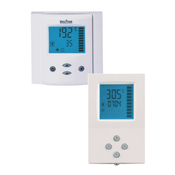
TCY3-T0121R Series Intelligent Compact Controller
Applications
•
Air Only Systems: Constant or Variable Air Volume systems for single or dual duct systems with options of:
up to two reheat stages
o
supply air, extract air cascade control
o
humidity control
o
Control for variable speed fans
o
•
Air/Water Systems:
Fan Coil units for 2-pipe or 4-pipe systems with options of:
o
radiator control, chilled ceiling
o
•
Water Only Systems: Radiator, floor heating or chilled ceilings
•
Individual room control for hotel rooms, meeting rooms, etc.
General Description
The TCY3 is a stand-alone electronic universal controller with two autonomous control loops. Each control loop may use up
to 2 PID sequences and 6 binary sequences. The TCY3-T0121R features 1 NTC temperature sensor and 1 analog input, 2
Binary Outputs and one analog output. The outputs need to be assigned to the control sequences by parameters. A
detailed configuration is possible by following a simple setup routine. The TCY3 can be configured using the standard
operation terminal. No special tool or software is required.
Doc: 70-000002 V1.0, 20101115
Subject to alteration
Humidity control
Pressure control
© Vector Controls GmbH, Switzerland
Features
•
Temperature control for 2-pipe, 4-pipe HVAC
systems.
•
-H version: Humidity control with integrated
humidity sensor
•
Universal PID and binary control for any
analog input/output signal and range
•
4 independent PID sequences, 12
independent binary sequences
•
1 modulating output for DC 0...10V or 0...20
mA actuators with 10 bit resolution.
•
1 Input for DC 0...5V, 0...10V or 0...20 mA
sensors with 10 bit resolution
•
1 internal temperature sensor and 1 external
sensor input
•
Multiple functions on external input: auto
changeover, remote control
•
Monitoring of low and high limits on all inputs.
Programmable reaction in case of alarm.
•
Feedback function for internal sensors and
set points.
•
Special functions for dehumidifying, set point
shift and VAV control
•
Transformation of display value according to
analog sensor range
•
Password protected programmable user and
control parameters
•
Blue backlight
•
Deluxe Version only:
Power Cap protected real time clock with 24h
o
power backup
16 switching times, grouped in 4 time
o
schedules.
Infrared remote control
o
TCY3-T0121R
Page 1
Advertisement
Table of Contents

Related Manuals for Vector TCY3-T0121R


Summary of Contents for Vector TCY3-T0121R
- Page 1 The TCY3 is a stand-alone electronic universal controller with two autonomous control loops. Each control loop may use up to 2 PID sequences and 6 binary sequences. The TCY3-T0121R features 1 NTC temperature sensor and 1 analog input, 2 binary outputs and one analog output. The outputs need to be assigned to the control sequences by parameters. A detailed configuration is possible by following a simple setup routine.
- Page 2 1 AO sensor TCY3-T0121R-H-U 40-10 0027 Standard 2” x 4” TCY3-T0121R-H-U-D 40-10 0028 Deluxe Dimensions [mm] (inch) 88 (3.5) 32 (1.2) (0.8) 73 (2.9) 32 (1.2) (0.6) Doc: 70-000002 V1.0, 20101115 © Vector Controls GmbH, Switzerland Page 2 Subject to alteration...
- Page 3 Dimensions (H x W x D), U-version Front part: 112 x 73 x 15 mm (4.4” x 2.9” x 0.6”) Power case: ø 58 x 32 mm (ø 2.3” x 1.3”) Weight (controller only) 180 g (6.3 oz) Weight (including package) 260 g (9.2 oz) Doc: 70-000002 V1.0, 20101115 © Vector Controls GmbH, Switzerland Page 3 Subject to alteration...
- Page 4 NTC 10kΩ @ 25°C (77°F) ) selectable by jumper WARNING: Power supply is half-wave rectified: Signal ground = Power ground Connect through a safety isolation transformer Doc: 70-000002 V1.0, 20101115 © Vector Controls GmbH, Switzerland Page 4 Subject to alteration...
- Page 5 With a Philips-type screw driver of size #2, carefully tighten the front holding screw to secure the front part to the mounting plate. This screw is located on the front lower side of the unit. There is no need to tighten the screw too much. Doc: 70-000002 V1.0, 20101115 © Vector Controls GmbH, Switzerland Page 5 Subject to alteration...
- Page 6 Clock (Deluxe version only): Operation modes may automatically be switched according to daytime and weekday. The clock symbol will be indicated if time programs are activated. • Infrared Remote Controller (Deluxe version only): use OPR-1 to control the unit remotely Doc: 70-000002 V1.0, 20101115 © Vector Controls GmbH, Switzerland Page 6 Subject to alteration...
- Page 7 Problem with the internal real-time clock. Time schedule programs are not operating, time related functions will not be accurate. Clear the error message with OPTION key. If error reappears, replace product. Doc: 70-000002 V1.0, 20101115 © Vector Controls GmbH, Switzerland Page 7 Subject to alteration...
- Page 8 Select switching time 00:00 to 23:45 in 15-minute steps; press OPTION to continue. • Repeat above two steps for each switching time. Access to time schedules may be disabled with UP04 Doc: 70-000002 V1.0, 20101115 © Vector Controls GmbH, Switzerland Page 8 Subject to alteration...
- Page 9 Clock settings The remote controller contains a daytime clock. The receiving TCY3-T0121R controller will adopt the OPR-1’s own clock whenever it received a command from it. In order to set the clock in the OPR-1, press HOUR and MINUTE button together until the clock starts blinking. Then set the correct time with the HOUR and MINUTE buttons.
- Page 10 02 = Humidity Input UP 12 = Display heating & cooling state in standard mode ON, OFF = Show heating and cooling while output is active Doc: 70-000002 V1.0, 20101115 © Vector Controls GmbH, Switzerland Page 10 Subject to alteration...
- Page 11 1L04 1L02 IP23 = ON IP26 = ON IP26 = OFF 1L01 IP23 = OFF 1L03 T [°C, F] U [V, mA] IP28 IP24 IP25 IP27 Doc: 70-000002 V1.0, 20101115 © Vector Controls GmbH, Switzerland Page 11 Subject to alteration...
- Page 12 TI = 60s, KI = 0.4 For dehumidifying systems: TI = 70s, KI = 0.3 Pressure Control (VAV): TI = 1s, KI = 0.8 (depending on speed of actuator KI varies) Doc: 70-000002 V1.0, 20101115 © Vector Controls GmbH, Switzerland Page 12 Subject to alteration...
- Page 13 Control speed will slow down when a large number of samples are used for an averaging signal. This should be taken into account when defining the control parameters. Compensation: Adjust input values if required Doc: 70-000002 V1.0, 20101115 © Vector Controls GmbH, Switzerland Page 13 Subject to alteration...
- Page 14 Humidity Input (-H Version) The TCY3-T0121R-H includes a capacitive-based humidity sensor with 3% accuracy. The sensor may be used as control input, as feedback or display input. It will replace the analog input on loop 2, if configured as control input.
- Page 15 The position of the floating output is calculated according to the sum of opening and closing time of the actuator. The total running time of the actuator must be entered. Doc: 70-000002 V1.0, 20101115 © Vector Controls GmbH, Switzerland Page 15 Subject to alteration...
- Page 16 Switching difference on floating output: Use the Switching difference parameter to reduce the switching frequency of the actuator. The actuator will only move, if the difference to the current actuator position is larger than this parameter. Doc: 70-000002 V1.0, 20101115 © Vector Controls GmbH, Switzerland Page 16 Subject to alteration...
- Page 17 10. Set user settings (UP) Configuration parameters for firmware version 3.1 The TCY3-T0121R can be adapted to a wide variety of applications. The adaptation is done through parameters. The parameters can be changed on the unit without the need of additional equipment.
- Page 18 Switching Hysteresis X 0…100° 0.5° (1.0°F) 1L 23 Delay Switching on / off 0…255s 1L 24 Delay Heat / Cool change over 0…255 Min 5 Min Doc: 70-000002 V1.0, 20101115 © Vector Controls GmbH, Switzerland Page 18 Subject to alteration...
- Page 19 Acc input 2L 21 Offset cooling stage 3: Q Acc input 2L 22 Switching Hysteresis X Acc input 2L 23 Delay Switching on / off 0…255s Doc: 70-000002 V1.0, 20101115 © Vector Controls GmbH, Switzerland Page 19 Subject to alteration...
- Page 20 Upper Limit: Input signal with maximum setpoint shift. IP 29 Hot / Cool Symbol while compensation is active ON, OFF OFF= Hide symbol ON= Show symbol Doc: 70-000002 V1.0, 20101115 © Vector Controls GmbH, Switzerland Page 20 Subject to alteration...
- Page 21 ON = open output (Output is on 100%) OP 09 Temperature feedback minimum temperature -40…215 °C 0°C (32°F) OP 10 Temperature feedback maximum temperature -40…215 °C 50° (122°F) Doc: 70-000002 V1.0, 20101115 © Vector Controls GmbH, Switzerland Page 21 Subject to alteration...
- Page 22 7 = Any alarm active (ALA1 – ALA4) OP 17 FO1 Action in case of alarm ON, OFF OFF = close output ON = open output Doc: 70-000002 V1.0, 20101115 © Vector Controls GmbH, Switzerland Page 22 Subject to alteration...
- Page 23 DO2: Action in case of alarm ON, OFF OFF = close output ON = open output OP 26 Display Fan Symbol while DO1 active ON, OFF Doc: 70-000002 V1.0, 20101115 © Vector Controls GmbH, Switzerland Page 23 Subject to alteration...
Need help?
Do you have a question about the TCY3-T0121R and is the answer not in the manual?
Questions and answers