Table of Contents
Advertisement
Quick Links
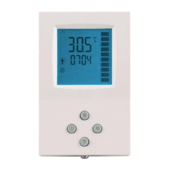
TLC3-FCR-T-U
Intelligent Fan Coil controller
Features
The PWM control option reduces room temperature fluctuations
and energy consumption
Low power energy consumption: < 1W per unit
Temperature control for 2- pipe fan coil systems.
External sensor or open contact for remote control,
external heat – cool change or auto-changeover on supply
temperature with selectable activation limits
Automatic fan control for three stage fans.
Cost saving option with Economy functionality and set point
limitations
Control for single stage heating, cooling and fan only operation
modes
Password protected programmable user and control parameters
Setpoint range limitation
o
Access control for setpoints, fan speeds and mode change
o
Access control for heat/cool change and time programs
o
Select your display contents
o
Selectable behavior after return from power failure
o
Temperature display in Celsius or Fahrenheit
Deluxe Version:
Clock and time schedule functions with power failure protection
Blue backlight for LCD
Infrared remote controller option:
With special features for Boost and delayed switching on or off
Applications
Air Only Systems:
Constant Air Volume systems with three stage fans for single or dual duct systems
o
Air/Water Systems:
Fan Coil units for 2-pipe systems
o
radiator control, chilled ceiling
o
Simple individual room control for hotel rooms, meeting rooms, etc.
PWM or On-Off-Control of 2 spring return valves or 3-point on-off or floating control of one 3-point valve.
General Description
The TLC3-FCR-T-U is a stand-alone electronic fan coil controller with one control loop. The TLC3-FCR-T-U features 1
NTC temperature sensor input, 1 external NTC or open contact input and four binary outputs (Relays).
A detailed parameterization is possible with the use of a simple configuration routine. The TLC3-FCR-T-U can be
configured using the standard operation terminal. No special tools or software is required.
Ordering
Item Name
TLC3-FCR-T-U-24
TLC3-FCR-T-U-24-W01
TLC3-FCR-T-U-120
TLC3-FCR-T-U-120-W01
TLC3-FCR-T-U-230
TLC3-FCR-T-U-230-W01
TLC3-FCR-T-U-D-24
TLC3-FCR-T-U-D-24-W01
TLC3-FCR-T-U-D-120
TLC3-FCR-T-U-D-120-W01
TLC3-FCR-T-U-D-230
TLC3-FCR-T-U-D-230-W01
Selection of actuators, fans and sensors
Temperature Sensors: Use only our approved NTC sensors to achieve maximum accuracy. Recommended is SDB-
Tn10-15 as Duct sensor, SRA-Tn10 as Room sensor and SDB-Tn10-15+AMI-10 as immersion sensor.
Binary auxiliary devices: E.g. fans, on/off valves, etc. Do not directly connect devices that exceed 2A. Observe startup
current on inductive loads! Do not connect more than one fan coil unit to one controller.
Doc: 70-00-0201, V3.0 Date: 20120404
Subject to alteration
Item code
Variant
Standard
40-10 0139
Cooling only
40-10 0139-01
Standard
40-10 0149
Cooling only
40-10 0149-01
Standard
40-10 0116
Cooling only
40-10 0116-01
Deluxe
40-10 0144
Cooling only
40-10 0144-01
Deluxe
40-10 0154
Cooling only
40-10 0154-01
Deluxe
40-10 0117
Cooling only
40-10 0117-01
© Vector Controls GmbH, Switzerland
TLC3-FCR-T-U Engineering Manual
Power
Features
24VAC/DC
120VAC
Fan coil controller with:
230VAC
1 TI int or ext
3 DO (Relay) Fan control
24VAC/DC
1 DO (Relay) Binary valve control
120VAC
230VAC
Page 1
Advertisement
Table of Contents

Related Manuals for Vector TLC3-FCR-T-U Series


Summary of Contents for Vector TLC3-FCR-T-U Series
- Page 1 Binary auxiliary devices: E.g. fans, on/off valves, etc. Do not directly connect devices that exceed 2A. Observe startup current on inductive loads! Do not connect more than one fan coil unit to one controller. Doc: 70-00-0201, V3.0 Date: 20120404 © Vector Controls GmbH, Switzerland Page 1 Subject to alteration...
-
Page 2: Technical Specification
60 x 50 x 32mm (2.4 x 2.0 x 1.3 in.) Distance for mounting screws: Horizontal 55 to 60mm (2.2 to 2.4 in.) Vertical: 55 to 93mm (2.2 to 3.7 in.) Doc: 70-00-0201, V3.0 Date: 20120404 © Vector Controls GmbH, Switzerland Page 2 Subject to alteration... -
Page 3: Mounting Location
Binary output 230V AC: Valve (Heating or cooling) External input: NTC 10kΩ @ 25°C (77°F) or open contact to SGND Signal common: 0 potential for inputs Doc: 70-00-0201, V3.0 Date: 20120404 © Vector Controls GmbH, Switzerland Page 3 Subject to alteration... -
Page 4: Display And Operation
External input for heat / cool auto-change-over missing or damaged. Verify wiring or setup. Steady: Frost protection is active. Blinking: Frost protection activated in the past and is now inactive. Confirm with OPTION key. Doc: 70-00-0201, V3.0 Date: 20120404 © Vector Controls GmbH, Switzerland Page 4 Subject to alteration... - Page 5 A blinking clock indicates that the time needs to be set. Time programs will not operate if the time is not defined. See chapter operation, advanced settings for instructions on how to set the time. Access to time schedules may be disabled with UP-04 Doc: 70-00-0201, V3.0 Date: 20120404 © Vector Controls GmbH, Switzerland Page 5 Subject to alteration...
- Page 6 Repeatedly pressing the mode button may activate the following operation modes: HEAT, COOL and FAN ONLY. The mode change may be disabled using the UP parameters. Note: The remote controller is currently only available in °C mode. Doc: 70-00-0201, V3.0 Date: 20120404 © Vector Controls GmbH, Switzerland Page 6 Subject to alteration...
- Page 7 The unit will switch automatically back to the scheduled mode when the reset time expires. = Reset of override mode is not active. 1…255 = delay in minutes to switch off device Doc: 70-00-0201, V3.0 Date: 20120404 © Vector Controls GmbH, Switzerland Page 7 Subject to alteration...
-
Page 8: Control Configuration
It is not recommended to use cycle times below 10 minutes as the lifetime of the relays will be shortened with frequent switching. For PWM applications requiring cycle times below 100 seconds we recommend using TLC3-FCR-2 with TRIAC outputs Doc: 70-00-0201, V3.0 Date: 20120404 © Vector Controls GmbH, Switzerland Page 8 Subject to alteration... - Page 9 Dry contact: Heating if contact closed FC18 > FC19 25°C (77F) 15°C (59F) Dry contact: Cooling if contact closed FC18 < FC19 15°C (59F) 25°C (77F) Doc: 70-00-0201, V3.0 Date: 20120404 © Vector Controls GmbH, Switzerland Page 9 Subject to alteration...
- Page 10 TLC3-FCR-T-U Engineering Manual Notes: Doc: 70-00-0201, V3.0 Date: 20120404 © Vector Controls GmbH, Switzerland Page 10 Subject to alteration...
Need help?
Do you have a question about the TLC3-FCR-T-U Series and is the answer not in the manual?
Questions and answers