Table of Contents
Advertisement
Quick Links
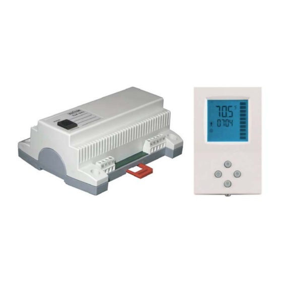
TLR-D5P-U Intelligent Package Unit Controller, Base and Terminal
General Description
The TLR-D5P-U is a stand-alone electronic package unit controller with one control loop. The TLR-D5P-U includes 1
internal NTC temperature sensor, one open/contact or external NTC temperature input and five binary outputs
(Relays). A detailed adaptation to local conditions is possible with the use of a simple configuration routine. The TLR-
D5P-U can be configured using the standard operation terminal. No special tools or software is required. The TLR-
D5P-U has been specifically developed to switch larger fans with switching power of up to 10(6) Amp. TLR-DP5-U
includes:
•
1 package unit control loop
•
1 internal temperature sensor or external temperature sensor input
•
1 binary output for fan control
•
2 binary outputs for cooling
•
2 binary outputs for heating
Deluxe Version:
•
Clock and time schedule functions with special options for schools and universities
•
Clock keeps running for 48 hours in case of power failure
•
Display with blue backlight
•
Infrared remote controller option with special features for Boost and delayed switching on or off
Features
•
Temperature control for 2- or 4-pipe package units (2 stages fan-supported heating or cooling with reversing
valve)
•
Temperature control for 2-pipe package units (fan-supported dual heating or cooling stages)
•
Temperature control for 4-pipe package units (1 stage fan-supported heating and cooling, optional 2 stage
heating or cooling)
•
Relays switching for outputs each up to 10(6)A
•
Large temperature range from –20°C to 70°C (-4°F to 158°F).
•
Control for heating, cooling and fan only operation
•
Adjustable start and stop delays to protect compressors and switching elements
•
Cost saving option with Economy functionality and set point limitations
•
External sensor or open contact for remote control, external heat/cool changeover or auto-changeover on
supply or outdoor temperature with selectable activation limits
•
Password protected programmable user and control parameters
Setpoint range limitation
o
Access control for setpoints, fan speeds and mode change
o
Access control for heat/cool change and time programs
o
Select your display contents
o
Selectable behavior after return from power failure
o
•
Temperature display in Celsius or Fahrenheit
Applications
•
Air-only systems: fan supported heating or/and cooling stages e.g. compressors, electric heaters.
•
Air/water systems: Induction units, fan supported dual coil units for 2- and 4-pipe systems
Doc: 70-07-0100, V2.2, Date: 20090201
TLR-D5P-U Engineering Manual
©2008 Vector Controls
Page 1
Advertisement
Table of Contents

Related Manuals for Vector TLR-D5P-U Series TLR-D5P-24


Summary of Contents for Vector TLR-D5P-U Series TLR-D5P-24
- Page 1 Temperature display in Celsius or Fahrenheit Applications • Air-only systems: fan supported heating or/and cooling stages e.g. compressors, electric heaters. • Air/water systems: Induction units, fan supported dual coil units for 2- and 4-pipe systems Doc: 70-07-0100, V2.2, Date: 20090201 ©2008 Vector Controls Page 1...
- Page 2 Duct sensor with housing, 12cm immersion depth 40-20 0051 SDB-Tn10-20 Duct sensor with housing, 20cm immersion depth 40-20 0004 SRA-Tn10 Room sensor 40-20 0005 SOA-Tn10 Outdoor sensor 40-20 0006 Dimensions [mm] (inch) Doc: 70-07-0100, V2.2, Date: 20090201 ©2008 Vector Controls Page 2...
-
Page 3: Technical Specifications
Dimensions (H x W x D) 57 x 147 x 115 mm (2.25 x 5.8 x 4.5 in) including package, base + terminal) Weight TLR-D5P-U-24 520 g (1.15 lb) TLR-D5P-U-230 570 g (1.25 lb) Doc: 70-07-0100, V2.2, Date: 20090201 ©2008 Vector Controls Page 3... -
Page 4: Selection Of Actuators And Sensors
13 T Stage 2/ Heat 2 Power for DO4 – DO5 14 GND Rev Valve/ Cool 1 15 T Cool 2 Attention: Max. switching power is limited to 250VAC, 10(6)A Doc: 70-07-0100, V2.2, Date: 20090201 ©2008 Vector Controls Page 4... -
Page 5: Mechanical Design And Installation
200 m (650ft). • Conductor resistance will influence external temperature reading. 450 Ω will result in an increase of 1°C (2°F). Compensate using UP-08 if external temperature is used to control unit. Doc: 70-07-0100, V2.2, Date: 20090201 ©2008 Vector Controls Page 5... -
Page 6: Display And Operation
Infrared Remote Controller: (Deluxe version only) use OPR-1 to control the unit remotely • Via external contact (comfort/economy) Note: Time programs will not operate, if operation mode is set to OFF by remote control or if time is not set. Doc: 70-07-0100, V2.2, Date: 20090201 ©2008 Vector Controls Page 6... -
Page 7: Error Messages
The TLR-D5P-U may display the following error condition: Err1: Temperature sensor faulty. The temperature sensor is damaged. Err2: External input for heat / cool auto change over missing or damaged. Frost protection is active. Doc: 70-07-0100, V2.2, Date: 20090201 ©2008 Vector Controls Page 7... -
Page 8: Operation Of The Terminal Unit
Select switching time 00:00 to 23:45 in 15-minute steps; press OPTION to continue. Repeat steps 3 and 4 for each switching time. Access to time schedules may be disabled with UP-04 Doc: 70-07-0100, V2.2, Date: 20090201 ©2008 Vector Controls Page 8... - Page 9 Repeatedly pressing the mode button may activate the following operation modes: HEAT, COOL and FAN ONLY. The mode change function on the TLR-D5P-U may be disabled using the UP00 parameters. Note: The remote controller is currently only available in °C mode. Doc: 70-07-0100, V2.2, Date: 20090201 ©2008 Vector Controls Page 9...
-
Page 10: Setting Of Parameters
= Reset of override mode is not active. 1…255 = delay in minutes to switch off device if ON/Economy mode is activated while the unit is scheduled to be in OFF mode Subject to alteration Doc: 70-07-0100, V2.2, Date: 20090201 ©2008 Vector Controls Page 10... -
Page 11: Control Functions
Rev. Valve if CP19 = 2 Frost 2 pipe system heat or cool Stage 1 Stage 2 Frost 4 pipe system Heating Stage 1 Stage 2 4 pipe system Cooling Stage 1 Stage 2 Doc: 70-07-0100, V2.2, Date: 20090201 ©2008 Vector Controls Page 11... - Page 12 The control output will be switched off when the setpoint is reached. The fan keeps running until stop delay has expired. This delay prevents overheating and condensation on the coils. Controls Output Fan Output Demand CP20 CP21 Time [s] Doc: 70-07-0100, V2.2, Date: 20090201 ©2008 Vector Controls Page 12...
-
Page 13: Input Configuration
A preset setpoint defined with CP16 for heating and CP17 for cooling is used instead of the selected setpoint. The setpoint shift feature is disabled. Doc: 70-07-0100, V2.2, Date: 20090201 ©2008 Vector Controls Page 13... -
Page 14: Configuration Of Controller
Press the POWER key again so as to leave the menu and return to the group selection. Press POWER while in the group selection to return to normal operation. The unit will return to normal operation if no key is pressed for more than 5 minutes. Doc: 70-07-0100, V2.2, Date: 20090201 ©2008 Vector Controls Page 14... - Page 15 Fan on delay (time the fan runs before stage switch on) 0…255 s 30 s CP 21 Fan off delay (time the fan keeps running after stage switch off) 0…255 s 90 s Subject to alteration Doc: 70-07-0100, V2.2, Date: 20090201 ©2008 Vector Controls Page 15...
Need help?
Do you have a question about the TLR-D5P-U Series TLR-D5P-24 and is the answer not in the manual?
Questions and answers