
Related Manuals for SDI HPDA-15RM-B1


Summary of Contents for SDI HPDA-15RM-B1
- Page 1 PECTRA YNAMICS, ERFORMANCE ISTRIBUTION MPLIFIER HPDA-15RM-B1 PERATING ANUAL PECTRA YNAMICS, NC • 1849 Cherry St. Unit 2. • Louisville, CO 80027 Phone: (303) 665-1852 • Fax: (303) 604-6088 www.spectradynamics.com...
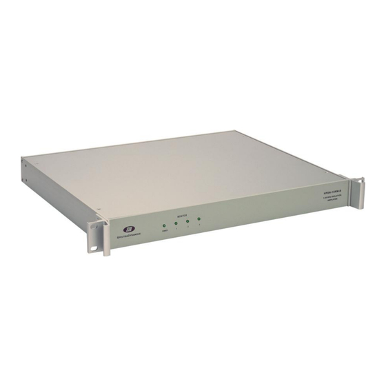
- Page 3 Description The standard unit HPDA-15RM-B is a high performance distribution and isolation amplifier that contains three HPDA modules. This HPDA-15RM-B1 unit is a modification of the standard unit that contains only two HPDA modules. One Input signal is used to feed the two HPDA modules.
-
Page 4: Safety And Preparation For Use
Line Voltage This instrument may be setup to operate on 100-120 or 220-240 VAC and a line frequency of 50 to 60 Hz. The setup voltage for this HPDA-15RM-B1 is specified on page 4. Fuse A 0.50 Ampere 250V slow-blow fuse is used for 100-120 VAC operation. -
Page 5: The Front Panel
The Front Panel AC Power LED The POWER LED is on when power is applied to unit and the unit is operating properly. Monitor LED The MONITOR LED labeled 1 will be on if all outputs on the first HPDA module have signal levels greater than +7 dBm. -
Page 6: The Back Panel
The Back Panel AC POWER ENTRY MODULE The HPDA-15RM-B1 is configured to operate on: 100-120 VAC 220-240 VAC SMA INPUTS The signal to be distributed should be connected to the SMA jack labeled INPUT. There are two amplifier modules, one input is driving both amplifier modules. -
Page 7: Operation
Plug the unit into an appropriate power outlet. A green LED on the front panel labeled “POWER” will turn on. Attach the signal to be distributed to any of the SMA input connectors on the back panel. Any HPDA-15RM-B1 output may be used to drive the input of another distribution module. -
Page 8: Specifications
Specifications PARAMETER CONDITIONS UNITS Max. Input Power 1 dB compression Bandwidth +/- 1 dB 1 - 20 Gain @ 5 MHz +/- 0.5 Impedance Input Ohms Output Return Loss Input (S11) 5MHz Output (S22) 5MHz Distortion +13 dBm Isolation Output to output Output to input Phase Noise 1 Hz... -
Page 9: Warranty
This warranty shall be in effect for one (1) year from the date a HPDA-15RM-B1 is sold by SDI. SDI makes no other warranty, express or implied, and makes no warranty of the fitness for any particular purpose. SDI’s obligation under this warranty shall not include any transportation charges or costs of installation or any liability for direct, indirect, or consequential damages or delay. - Page 10 HPDA-15RM-B1:1I-10O/R02...
Need help?
Do you have a question about the HPDA-15RM-B1 and is the answer not in the manual?
Questions and answers