
Related Manuals for SDI PD-100i


Summary of Contents for SDI PD-100i
- Page 1 PECTRA YNAMICS PD-100i PULSE DISTRIBUTION AMPLIFIER PERATING ANUAL SPECTRADYNAMICS, INC • 1849 Cherry St. Unit 2. • Louisville, CO 80027 Phone: (303) 665-1852 • Fax: (303) 604-6088 www.spectradynamics.com...
- Page 2 PD-100i Pulse Distribution Amplifier Operating Manual Copyright © 2018 SpectraDynamics, Inc. All rights reserved. PD-100i:R02-2018/LA...
-
Page 3: Table Of Contents
Contents Introduction ……………………………………………………………………..1 Safety and preparation for use ………………………………..……….…….. 2 2.1 Electrical ……………….…………………………………………….……. 2 2.2 Instrument ……..…………….………………………………….….…….. 3 Front panel description …….…………………………………………….…… 4 Back panel description ………………………………………………….……. 5 Operation ……………………………………………………………………… Specifications …………………………………………………………………. 7 Warranty and service ………………………………………………………… 8... -
Page 5: Introduction
Fourier frequencies greater than 10 kHz. All outputs are DC coupled and conform to TTL specifications. The PD-100i is designed to be powered by a 100 to 240 VAC mains source or by a +12 to +36 VDC power source if the instrument was acquired with the DC power option. The... -
Page 6: Safety And Preparation For Use
Detaching the AC power cord is the only option of disconnecting the unit from the AC mains supply. Make sure you have access to the rear panel or provide an external accessible AC disconnect means for your PD-100i. DC Power... -
Page 7: Instrument
Do not apply negative voltages as they will damage the pulse distribution amplifier. RF Signals The second module of the PD-100i is designed to distribute RF signals. The recommended input levels are +7 to +20 dBm. Greater power levels will damage the unit and void all war- ranties. -
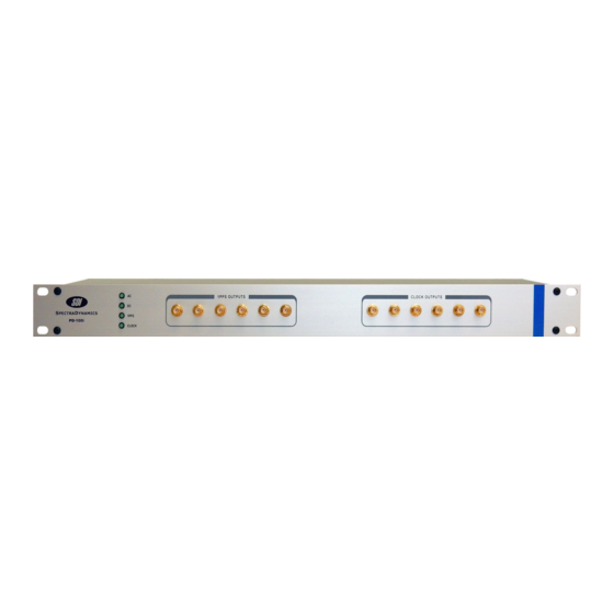
Page 8: Front Panel Description
Front Panel The AC Power LED turns on when AC power is applied to unit. The DC Power LED is on when DC power is applied to unit. 1PPS The 1PPS LED flashes on the falling edge of the 1PPS output signal. CLOCK The CLOCK LED will be on if an RF signal is present at the CLOCK input. -
Page 9: Back Panel Description
Back Panel AC POWER The PD-100i is configured to operate on 100 to 240 VAC. DC POWER Optional Battery Backup Connector for DC Backup power source. 1PPS IN The 1 PPS signal to be distributed should be connected to the SMA jack labeled 1 PPS INPUT. -
Page 10: Operation
If you supply AC power to the unit, the LED on the front panel labeled AC Power will turn on. If you apply DC power to the PD-100i the DC power LED located on the front panel should light up. -
Page 11: Specifications
Specifications PPS Distribution Module PARAMETER CONDITIONS UNITS Rise time 10 - 90 % Fall time 10 - 90 % Propagation delay 50 ohm load Differential delay Channel - Channel Impedance input Ohms output Input High Level Input signal into 50 ohm load Input Low Level Input signal into 50 ohm... -
Page 12: Warranty And Service
SDI’s option, any product not meeting the said specifications. This warranty shall be in effect for one (1) year from the date a PD-100i is sold by SDI. SDI makes no other warranty, express or implied, and makes no warranty of the fitness for any particular pur- pose.
Need help?
Do you have a question about the PD-100i and is the answer not in the manual?
Questions and answers