Table of Contents

Related Manuals for SDI PD5-RM-B


Summary of Contents for SDI PD5-RM-B
- Page 1 PECTRA YNAMICS, ULSE ISTRIBUTION MPLIFIER PD5-RM-B PERATING ANUAL PECTRA YNAMICS, NC • 1849 Cherry St. Unit 2. • Louisville, CO 80027 Phone: (303) 665-1852 • Fax: (303) 604-6088 www.spectradynamics.com...
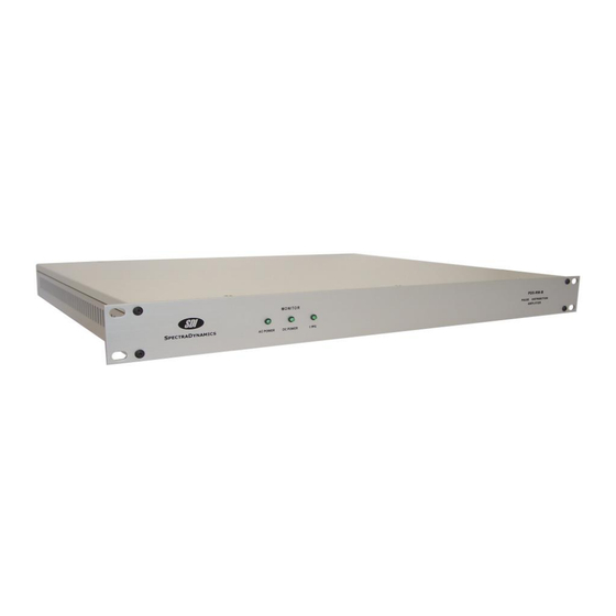
- Page 3 Description The PD5-RM-B is a TTL pulse distribution amplifier that accepts one input and provides five outputs. The outputs are designed to drive low impedance loads and long 50 or 75-ohm cables. The propagation delay through the amplifier is typically 10 ns. The channel-to-channel delay differences are less than 1 ns.
-
Page 4: Safety And Preparation For Use
Line Voltage This instrument may be setup to operate on 100-120 or 220-240 VAC and a line frequency of 50 to 60 Hz. The setup voltage for this PD5-RM-B is specified on page 4. Fuse A 0.50 Ampere 250V slow-blow fuse is used for 100-120 VAC operation. -
Page 5: The Front Panel
LED should be on when DC power is applied and the unit is operating properly. If the PD5-RM-B is not equipped with the battery backup option, the DC POWER LED will not be connected but will still be on the front panel. -
Page 6: The Back Panel
The Back Panel The Back Panel AC POWER ENTRY MODULE The PD5-RM-B is configured to operate on: 100-120 VAC 220-240 VAC DC POWER ENTRY MODULE Optional Battery Backup Connector for +24 VDC Backup power source. SMA INPUT 1 PPS input. The input signal should conform to TTL levels. -
Page 7: Battery Backup Module
Battery Backup Module Description If you acquired the optional battery backup module for your PD5-RM-B you will be able to power your instrument with an external +24 VDC power source. In case of loss of the main AC power this module will automatically power the unit. The switch from AC to DC supply operation is affected by a Schottky diode network and charge storage capacitors to ensure glitch free operation. - Page 8 The +24 VDC connector is wired as follows: Pin 1 NC Pin 2 NC Pin 3 NC Pin 4 +24 VDC GND return Pin 5 +24 VDC power Pin 6 Chassis GND / Earth GND Copyright © SpectraDynamics, Inc. 2010...
-
Page 9: Operation
Low-Level Input Voltage -1.2 VDC Minimum DC Voltage Applied at Output 7 VDC Maximum Storage Temperature -10 to +75 ºC Operation Environment 0 to +50 ºC 1U H, 19“ W, 14” D Rack Mount Chassis Copyright © SpectraDynamics, Inc. 2010... -
Page 10: Specifications
50 ohm load Output Low Level 50 ohm load Temperature-delay 0 - 50 ºC ps/ºC Coefficient 25 - 35 ºC The rise and fall times were tested with a TTL input signal at 100 kHz. Copyright © SpectraDynamics, Inc. 2010... -
Page 11: Warranty
SDI’s option, any product not meeting the said specifications. This warranty shall be in effect for one (1) year from the date a PD5-RM-B is sold by SDI. SDI makes no other warranty, express or implied, and makes no warranty of the fitness for any particular purpose. - Page 12 PD5-RM-B:1I-5O/R02...
Need help?
Do you have a question about the PD5-RM-B and is the answer not in the manual?
Questions and answers