
Related Manuals for SDI HPDA-15RMi-CW


Summary of Contents for SDI HPDA-15RMi-CW
- Page 1 PECTRA YNAMICS HPDA-15RMi-CW 1-100 MHz ISOLATION AMPLIFIER OPERATING MANUAL SPECTRADYNAMICS, INC • 1849 Cherry St. Unit 2 • Louisville, CO 80027 Phone: (303) 665-1852 • Fax: (303) 604-6088 www.spectradynamics.com...
- Page 2 HPDA-15RMi-CW 1-100 MHz Isolation Amplifier Operating Manual Copyright © 2020 SpectraDynamics, Inc. All rights reserved. HPDA-15RMi-CW:R01-2021-FA-MD...
-
Page 3: Table Of Contents
Contents Introduction ……………………………………………………………………..1 Safety and preparation for use ………………………………..……….…….. 2 2.1 Electrical ……………….…………………………………………….……. 2 2.2 Instrument ……..…………….………………………………….….…….. 3 Front panel description …….…………………………………………….…… 4 Back panel description ………………………………………………….……. 5 Installation ……………………………………………………………….…….. 6 Operation ……………………………………………………………………… Troubleshooting ………………………………………………………………. 8 Specifications …………………………………………………………………. 9 Warranty and service …………………………………………………………... -
Page 5: Introduction
LED for the corresponding module will turn off indicating a fault condition. The HPDA-15RMi-CW is designed to be powered by a 100 to 240 VAC mains source or by a +12 to +36 VDC power source. The DC power module may be used as a main power source for the instrument or in conjunction with the AC power module as a backup power supply in case of loss of the main AC power. -
Page 6: Safety And Preparation For Use
2.0 Safety and Preparation for Use The HPDA-15RMi-CW was designed for indoor use only and is not intended for operation outdoors or in a wet environment. The instrument may be mounted in a standard 19-inch instrumentation rack or may be used on a laboratory bench. -
Page 7: Instrument
2.2 Instrument Safety and Preparation for Use The HPDA-15RMi-CW is designed to distribute RF signals with a frequency of 1 to 100 MHz . The recommended level for the RF input signal is 0 dBm to +15 dBm. Any output level below 0 dBm will trigger a fault condition turning off the monitor LED for the corresponding RF module. -
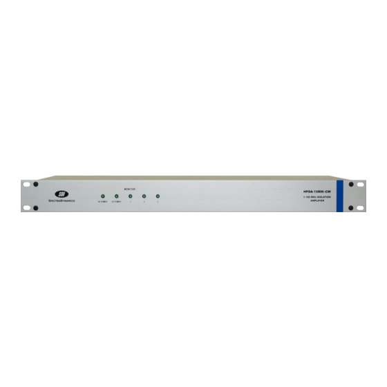
Page 8: Front Panel Description
0 dBm. RF signal levels less than 0 dBm will trigger a fault condition and the Monitor LED will not light up. However the HPDA-15RMi-CW will still provide five buffered copies per distribution module of the RF input signal on the back panel. -
Page 9: Back Panel Description
This instrument may also operate on DC power from +12 to +36 VDC as the main power supply. When the HPDA-15RMi-CW is set up to operate with both AC and DC power sources at the same time the DC power is used as backup power in case of AC power outages. -
Page 10: Installation
The instrument may be mounted in a standard 19-inch instrument rack or may be operated on a laboratory bench. Connecting Power The HPDA-15RMi-CW ships with a standard North American or European IEC power cord and a RM12BPE-6S(81) DC connector . You may prepare a DC power cable with the DC connector following the connector configuration on page 3. -
Page 11: Operation
Plug the power cord into an appropriate AC power outlet. You may also connect the DC power cable to an appropriate DC power supply. The HPDA-15RMi-CW is designed to distribute signals from 1 MHz to 100 MHz. The RF input has a 50-ohm input impedance. Provide a signal within the mentioned frequency range to the any of the SMA connectors available on the back panel labeled INPUT. -
Page 12: Troubleshooting
If any fuse is blown replace with same type and rating. Please contact SDI if the any of the fuses blow again or if the event that caused the fuse to blow is not known. -
Page 13: Specifications
8.0 Specifications Specifications for Part Numbers HPDA-15RMi-CW and HPDA-15RMi-C2W PARAMETER CONDITIONS UNITS Input power level 1 dB compression Bandwidth +/- 1 dB 1 - 100 1 - 100 Gain @ 10 MHz Impedance Input Ohms Output Return loss Input (S11) 10 MHz... - Page 14 8.0 Specifications Specifications for Part Numbers HPDA-15RMi-C1W and HPDA-15RMi-C3W PARAMETER CONDITIONS UNITS Input power level 1 dB compression Bandwidth +/- 1 dB 1 - 100 1 - 100 Gain @ 10 MHz Impedance Input Ohms Output Return loss Input (S11) 10 MHz Output (S22) 10 MHz Distortion +13 dBm...
- Page 15 8.0 Specifications Rackmount chassis 1U H, 19“ W, 14” D Weight 4.5 kg, (10 lbs) AC Input Voltage Range 90-264 VAC, 22 W, 47-63 Hz DC Input Voltage Range 12-36 VDC, 13 W Storage temperature -10 to +75 ºC Operation environment 0 to +50 ºC Humidity 5% to 95% Non-condensing...
-
Page 16: Warranty And Service
Do not attempt to service or adjust the instrument unless another person, capable of providing first aid or resuscitation, is present. Please remember that any alteration or repair may void the warranty. Contact SDI with any questions or to request an RMA if a repair is needed. - Page 17 EC Declaration of Conformity The HPDA-15RMi-CW distribution amplifier has been designed and manufactured in accordance with the below referenced Standards and complies with all essential requirements of the Directives listed below. Directives: 2014/35/EU of the European Parliament and of the Council of 26 February 2014 on the harmonization of the laws of the Member States relating to the making available on the market of electrical equipment designed for use within certain voltage limits.
Need help?
Do you have a question about the HPDA-15RMi-CW and is the answer not in the manual?
Questions and answers