Sign In
Upload
Manuals
Brands
Ametek Manuals
Power Supply
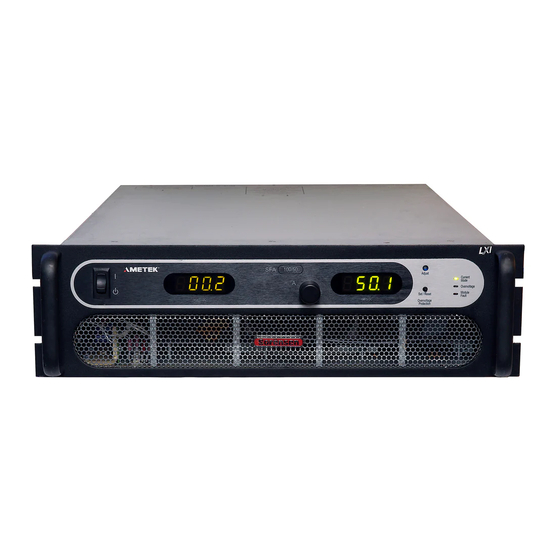
Sorensen SFA Series
Ametek Sorensen SFA Series Manuals
Manuals and User Guides for Ametek Sorensen SFA Series. We have
1
Ametek Sorensen SFA Series manual available for free PDF download: Operation Manual
Ametek Sorensen SFA Series Operation Manual (64 pages)
Brand:
Ametek
| Category:
Power Supply
| Size: 0 MB
Table of Contents
Table of Contents
15
Overview
19
General Description
19
Figure 1-1. Model Number Decoding
19
Technical Specifications
20
Environmental Characteristics
20
Electrical Characteristics
21
Physical Characteristics
23
Installation
25
Inspection
25
Contents of Shipment
25
Input/Output Connections
26
Location and Mounting
27
Chassis Removal from Rack
27
Table 2-1. 5Kw to 15Kw and 20Kw to 30Kw Series Input/Output Connectors
28
Table 2-2. Input Connections
28
Table 2-3. Output Connections
28
Wire Selection
30
Wire Size
30
Table 2-4. Minimum Wire Size
30
Table 2-5 Wire Resistance and Voltage Drop
31
Load Considerations
32
Inductive Loads
32
Outline Drawings
32
Table 2-6 Maximum AC Current Ratings
32
Table 2-7 Recommended Lugs
32
Table 2-8. Recommended Sense Connector Tools
32
Figure 2-1. SFA Series Outline Drawing, 3U Models, 5Kw to 15Kw
33
Figure 2-2. SFA Series Outline Drawing, 6U Models, 20Kw to 30Kw
34
Operation
35
Controls and Indicators
35
Figure 3-1. Front Panel Controls and Indicators (3U Model Shown)
35
Figure 3-2. Rear Panel Connectors (3U Model Shown)
37
Shaft Lock (Option)
38
Local Operation
38
Figure 3-3. Shaft Lock
38
Floating and Polarized Output
39
Initial Setup
39
Current Mode Operation
40
Overcurrent Protection
40
Analog Control Connector (J1)
41
Figure 3-4. ANALOG CONTROL Connector (J1) Pin-Out
42
Table 3-1. ANALOG CONTROL Connector (J1), Designations and Functions
44
Remote Current Programming
45
Figure 3-5. Remote Current Programming Using Resistance
45
Remote Sensing
46
Figure 3-7. Remote Sensing Operation at the Load
47
Remote Output On/Off Control
48
Figure 3-8. Remote On/Off Control by Contact Closure
48
Figure 3-9. Remote On/Off Using Isolated AC or DC Voltage Source
48
Remote Overcurrent Setpoint
49
Figure 3-10. Remote On/Off Using Isolated TTL/CMOS Voltage Supply
49
Figure 3-11. Remote Overcurrent Set Using DC Voltage Source
49
Remote Shutdown (S/D)
50
Master/Slave Operation
50
Parallel Operation
50
Figure 3-12. Remote Shutdown Using DC Voltage Source
50
Figure 3-13. Master/Slave Connection
51
Verification and Calibration
53
Introduction
53
Verification and Calibration Cycle
53
Preparation
53
Standard Verification and Calibration Procedure
54
Current Mode
54
Figure 4-1. Precision Current Shunt
54
Resistor Programming Current Sources
55
Isolated Analog (Option) Verification and Calibration Procedure
55
Current Mode
56
Figure 4-2. Potentiometer Locations
57
Maintenance
59
Introduction
59
Preventive Maintenance
59
Table 5-1. Recommended Annual Inspection
60
Fuses
61
Table 5-2. Fuse Values
61
Advertisement
Advertisement
Related Products
AMETEK Sorensen SGI Series
Ametek Sorensen SGA Series
Ametek Sorensen SGA Series DC
Ametek Sorensen SG Series
Ametek Sorensen SGA
Ametek Sorensen SGI
Ametek Sorensen XDL Series II
Ametek Sorensen DCS-E 3kW Series
Ametek Sorensen XTR100-8.5
Ametek Sorensen XTR8-100
Ametek Categories
Measuring Instruments
Test Equipment
Power Supply
Switch
Controller
More Ametek Manuals
Login
Sign In
OR
Sign in with Facebook
Sign in with Google
Upload manual
Upload from disk
Upload from URL