Table of Contents
Advertisement
Quick Links
Advertisement
Table of Contents

Subscribe to Our Youtube Channel
Related Manuals for Renogy X 48V 5000W


Summary of Contents for Renogy X 48V 5000W
- Page 2 The illustrations in the user manual are for demonstration purposes only. Details may appear slightly different depending on product revision and market region. Renogy reserves the right to change the information in the user manual without notice. For the latest user manual, visit renogyx.com.
-
Page 3: Table Of Contents
1.4. Key Features ..............................2 1.5. SKU ................................... 2 1.6. Anti-lslanding Effect ............................2 2. Get to Know RENOGY X Hybrid Inverter ..........3 2.1. What’s In the Box? ............................3 2.2. Recommended Tools ............................3 2.3. Optional Accessories ............................4 2.4. - Page 4 USER - STATISTIC ............................60 7. Troubleshooting .................61 8. Dimensions & Specifications ..............64 8.1. Dimensions ..............................64 8.2. Technical Specifications ..........................64 9. Maintenance ..................67 9.1. Inspection ..............................67 9.2. Cleaning ................................. 67 9.3. Storage ................................67 Emergency Responses ................68 Renogy Support ..................69...
-
Page 5: General Information
General Information 1.1. Symbols Used The following symbols are used throughout the user manual to highlight important information. WARNING: Indicates a potentially dangerous condition which could result in injury or death. CAUTION: Indicates a critical procedure for safe and proper installation and operation. NOTE: Indicates an important step or tip for optimal performance. -
Page 6: Introduction
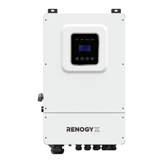
1.3. Introduction RENOGY X Hybrid Inverter works as a powerful inverter, a battery charger, and a high-speed AC transfer switch. It can convert solar energy to AC power and store power into lithium iron phosphate batteries. Featuring optimized self-consumption, the inverter stores power in batteries for future use or feeds the power to the grid. -
Page 7: Get To Know Renogy X Hybrid Inverter
Get to Know RENOGY X Hybrid Inverter 2.1. What’s In the Box? RENOGY X Hybrid Inverter × 1 User Manual × 1 Wi-Fi Logger × 1 M6 x 50 mm CT × 2 Expansion Screws × 6 (including two extras) Make sure that all accessories are complete and free of any signs of damage. -
Page 8: Optional Accessories
2.3. Optional Accessories AURA Lithium Iron Phosphate Battery System Meter Solar Panel Fuse You can buy optional accessories from renogyx.com. — 4 —... -
Page 9: Product Overview
2.4. Product Overview █ Exterior LOAD1 Port COM3 Port COM2 Port COM1 Port COM Port Dust-proof Cover PV Switch RSD Button Mounting Holes BAT Port Ground Port PV+ Port — 5 —... - Page 10 █ Interior (with the Dust-proof Cover removed) CAN2 CAN1 Type-C Update RS485 CAN1 and CAN2 are used to connect Renogy X inverters in parallel. Type-C Update Port is used to upgrade the software in the inverter. For details, contact renogyx.com. — 6 —...
-
Page 11: System Setup
2.5. System Setup █ System Wiring Positive (DC) Negative (DC) Ground Grid Power Utility Meter Main Electrical Panel Load Center AC Generator Critical Loads Non-Critical Loads 48V Battery The wiring diagram only shows the key components in a typical DC-coupled residential energy storage system for the illustrative purpose. - Page 12 █ Inverter Wiring Live wire (AC) Positive (DC) Ground Neutral wire (AC) Negative (DC) Communication AC Loads AC Load Center AC Load Center AC Loads L1 L2 N PE L1 L2 N 48V Battery Grounding PV 1 PV 2 PV 3 PV 4 AC Generator Grid Power...
-
Page 13: Preparation
Preparation 3.1. Plan a Mounting Site The inverter is designed for outdoor installation (IP65 rated). Make sure the installation site meets the following conditions: Not in direct sunlight. Not exposed to rain or snow. Not in areas where highly flammable materials are stored. Not in potential explosive areas. Not in the cool air directly. -
Page 14: Check The Inverter
Risk of explosion! Never install the inverter in a sealed enclosure with flooded batteries! Do not install it in a confined area where battery gases can accumulate. Keep the inverter out of the reach of children and animals. Do not expose the inverter to flammable or harsh chemicals or vapors. If the inverter is installed improperly on a boat, it may cause damage to components of the boat. -
Page 15: Check The Battery
2. Ensure the PV Switch is set to OFF when installing the inverter. PV SWITCH 3.3. Check the Battery Recommended Components 48V Battery Battery Adapter Cable (4/0 AWG) Grounding Cable (7 AWG) Prepare a proper grounding cable by yourself based on the 48V battery you use. This manual takes AURA Lithium Iron Phosphate Battery System as an example. -
Page 16: Check The Solar Panel(S) (Optional)
2. This Inverter supports a maximum System Voltage system voltage of 60V. Read the user manual for battery voltage Battery or Battery Pack System Voltage = System Voltage U parameters, and calculate the Batteries in Series Batteries in Parallel voltage of the battery or battery pack system according to the System Voltage U: U System Voltage U: U... - Page 17 4. Ensure the total power of all the Model Total Power solar panels complies with the value listed in the table. RENOGY X 48V 5000W Hybrid 7500W Max Inverter (RIV4850HI-SPS) RENOGY X 48V 8000W Hybrid 12000W Max Inverter (RIV4880HI-SPS) 5.
-
Page 18: Check The Ac Generator Or The Grid (Optional)
6. Strip some insulation (18 mm) off the cables with a wire stripper. 18mm 7. Insert the bare ends of the Solar Panel Extension Cables into the Cold- Pressed Terminals, and use Cold-Pressed Terminal Crimping Pliers to crimp the ends into the terminals. Ensure the cables are securely fixed to the Cold-Pressed Terminals. - Page 19 1. Inspect the Bare Wires for any visible damage including cracks, dents, deformation, and other visible abnormalities. All connector contacts shall be clean, dry, and free of dirt and corrosion. 2. Strip some insulation (18 mm) off the cables with a wire stripper. 18mm 3.
-
Page 20: Installation
Installation 4.1. Mount the Inverter 1. Place the inverter to the wall. Mark the mounting locations with a Marker Pen. 2. Remove the inverter. If the inverter is installed on a concrete or masonry wall, drill the pilot holes with the Hammer Drill and the Masonry Drill Bit at the marked locations. -
Page 21: Remove The Dust-Proof Cover
4.2. Remove the Dust-proof Cover Remove the Dust-proof Cover from the inverter by using an Inner Hexagon Spanner (M5) 4.3. Ground the Inverter Recommended Components Grounding Cable (7 AWG) 1. Remove the screw on the Ground Port with a Phillips Screwdriver (#2). 2. -
Page 22: Connect The Inverter To A Battery
4.4. Connect the Inverter to a Battery █ Wiring Diagram Communication 48V Battery The inverter can communicate with the connected battery only when the battery management system is compatible with that of the inverter. █ Power Cable Wiring 1. Run the Battery Adapter Cables (with the ends with ring terminals) and the Grounding Cable (with the ring terminal) through the grommet of the BAT Port. - Page 23 3. Remove one of the grounding screws from the inverter, and connect the Grounding Cable Ring Terminal to the grounding port of the inverter with the removed screw by using the Phillips Screwdriver (#2). 4. Connect the other end of the positive Battery Adapter Cable to the positive end of the battery, and the negative cable to the negative...
-
Page 24: Connect The Inverter To A Solar Panel (Optional)
2. Connect the RJ45 connector to BMS-485/BMS-CAN on the inverter and the other end to the communication port of the battery. Communication 48V Battery For details on how to connect the battery to the inverter, read the user manual of the battery. 4.5. - Page 25 For your safety, it is recommended to connect a fuse between the solar panel and the inverter. The fuse protects the inverter and other connected components, improving the security of the whole system. In the formula, I represents the maximum output current of the solar panel, and 1, 2 or 3 represents the solar panel number respectively.
-
Page 26: Connect The Inverter To An Ac Generator (Optional)
4. Connect the other end of the negative Solar Panel Extension Cable to the negative port of the solar panel. Connect the other end of the positive Solar Panel Extension Cable to the solar panel with a fuse. 4.6. Connect the Inverter to an AC Generator (Optional) █... - Page 27 CTs”. For details on how to install a current transformer (CT) to an AC generator, see “Install For single-phase generators, only GEN L1 is used. For split-phase generators, both GEN L1 and GEN L2 are used. █ Power Cable Wiring 1.
- Page 28 4. Complete grounding of the AC Generator in accordance with instructions in the user manual of the generator. AC Generator Grounding █ Communication Wiring For AC Generators supporting automatic on/off, connect the generator to the inverter via the DRYO_1A and DRYO_1B ports.
- Page 29 3. Run the two Signal Lines (with the ends with Cold-Pressed Terminals) through the grommet of the COM3 Port. 4. Insert the Cold-Pressed Terminals into the DRYO_1A and DRYO_1B ports on the inverter. When you hear a “click” sound, the Signal Line is firmly installed on the Click inverter.
- Page 30 To configure the AC Generator through the inverter, choose “USER > 1. SETUP > PASSORD CHECK > 16. Generator” on the LCD of the inverter. Parameter Settings Interface Description This interface shows general settings for the connected generator. 1. When the battery SOC drops below START SOC, the inverter automatically powers on the AC Generator to charge the battery.
-
Page 31: Connect The Inverter To The Grid (Optional)
4.7. Connect the Inverter to the Grid (Optional) █ Wiring Diagram Grid Power (120V/240V) CTs”. For details on how to install a current transformer (CT) in a system, see “Install For single-phase grid systems (such as in Europe, Africa, Asia, and Australia), only GEN L1 is used. For split- phase grid systems (such as in North America), both GEN L1 and GEN L2 are used. -
Page 32: Install Cts
2. Plug two Cold-Pressed Terminals of the Bare Wires to the GRID L1 and L2 ports of the inverter. Insert the rest Cold-Pressed Terminal of the Bare Wire to the GRID N port of the inverter. When you hear a “click” sound, the Bare Wire is firmly installed on the inverter. - Page 33 1. Run the RJ45 connectors of the CTs through the COM2 Port grommet on the inverter. 2. Connect the RJ45 connectors to CT L1 and CT L2 ports on the inverter. 3. The illustrations take the CT L1 port as an example. The same installation rules apply to the CT L2 port.
-
Page 34: Connect The Inverter To Ac Loads (Appliances)
5. Close the CT when you hear a “click” sound. 4.9. Connect the Inverter to AC Loads (Appliances) The inverter works in both on-grid and off-grid scenarios via the LOAD1 and LOAD2 ports. When connected to the grid or (and) a generator, the inverter powers AC loads via the grid first and then the generator. In off-grid mode (not connected to the grid or a generator), the inverter powers AC loads by using energy stored in the connected battery. - Page 35 Either LOAD1 or LOAD2 can output a maximum of 5000W or 8000W power. For scenarios involving both LOAD1 and LOAD2, the total output power of LOAD1 and LOAD2 stands at up to 5000W (for RENOGY X 48 V 5000W Hybrid Inverter) or 8000W (for RENOGY X 48 V 8000W Hybrid Inverter).
- Page 36 2. Insert the bare ends of the Bare Wires into the Cold-Pressed Terminals, and use Cold-Pressed Terminal Crimping Pliers to crimp the ends into the terminals. 3. Run the three Bare Wires (with the ends with Cold-Pressed Terminals) and the Grounding Cable (with the ring terminal) through the grommet of the LOAD1 Port.
- Page 37 6. Remove the front cover of the AC load center and connect the two live wire busbars with a copper strip. 7. Connect the AC Output cable of the inverter to the distribution box. The live wire is connected to the (L) terminal.
-
Page 38: Wi-Fi Connection
3. Turn the nut of the Wi-Fi Logger clockwise to fasten the logger to the inverter. Power on the inverter, and start the Renogy X Home app. Follow the instructions in the app to connect the inverter to the Wi-Fi Logger. -
Page 39: Check All Wires
4.11. Check All Wires Check and confirm all wires are firmly fastened to the inverter. 4.12. Install the Dust-proof Cover Install the Dust-proof Cover on the inverter by using an Inner Hexagon Spanner (M5). — 35 —... -
Page 40: Power On/Off And Configuration
Power On/Off and Configuration 5.1. Power On After completing all connections, power on the battery and press the RSD Button on the inverter to turn it on. The LCD lights up simultanesously. Prior to configuring the inverter, ensure all power supplies except the battery are OFF. The inverter cannot be powered on when the battery voltage is lower than 40V. - Page 41 █ Wi-Fi Logger LEDs You can check the operating status of the Wi-Fi logger through the embedded LEDs. Note that all LEDs are green lights. Implication Status Description Off: The logger fails to communicate with the router. Indicates the Slow flash (on for 1s/Off for 1s): Communication with the router communication succeeded.
-
Page 42: Configure Grid, Solar Panel, And Battery Parameters
Fault Fault Cause Solution COM READY Description 1. Connection between 1. Check the connection between the logger and the the logger and the inverter. The power inverter is loosen or Remove the logger and re- supply of abnormal. install it to the inverter. the logger is 2. -
Page 43: Choose A Working Mode
5.4. Choose a Working Mode The inverter supports three in-built working modes: SELFCONSUME, PEAK SHIFT, and BAT PRIORITY. You can choose one on demand. Alternatively, you can customize your mode by referring to “5.5. Advanced Mode Settings”. If the Anti-Reflux function is enabled, the inverter will not feed power to grid. 5.4.1. - Page 44 █ When the inverter is connected to a solar panel and a battery The connected loads are powered by the solar panel. If the solar power is sufficient to supply all the connected load, the surplus power is used to charge the battery. The connected loads are first powered by the solar panel and then by both the solar panel and battery when the solar power is insufficient to supply all the connected loads.
- Page 45 █ When the inverter is connected to the grid and a battery Grid In charge mode, both the connected loads and the battery are supplied by the grid. Grid In discharge mode, the connected loads are powered by the battery when the rated power of the loads is less than the battery power.
-
Page 46: Advanced Mode Settings
5.5. Advanced Mode Settings The hybrid inverter can be programmed to control how and when to use grid power. The advanced mode allows management of flexible loads and time-of-use billing. There are three advanced modes available: Sell First Mode, Limit Grid Mode and Zero Export Mode. Sell First Mode In this mode, the AntiReflux setting is automatically disabled. - Page 47 Working Mode Interface Description MODE SET 1. Disable 2. Sell First Sets the working mode of the inverter. 3. Limit Grid 4. Zero Export Advan Ctrl Interface Description 1. Global control. Indicates whether the grid can charge the battery. ADVAN CONTROL 2.
-
Page 48: Operation
5.6. Operation After the inverter is set up, remove the shading from the solar panels and turn the inverter PV Switch to the ON position. Power on the grid or the generator, and the inverter starts to work. PV SWITCH Please do not operate the inverter while it is in operation. -
Page 49: Power Off
5.8. Power Off 1. Turn off all connected loads. Press the RSD Button when the inverter is on, and the RSD Button will pop up. The inverter will automatically shut down. 2. Set the PV Switch to OFF and power off all the connected supplies. PV SWITCH When accessing the internal circuit of inverter, it is very important to wait 5 minutes before operating the power circuit or demounting the electrolyte capacitors inside the device. -
Page 50: Parameter Configuration
Parameter Configuration 6.1. Check General Parameters You can press on the LCD Screen to configure the general parameters for your system. Parameter Interface Description This interfaces displays error code and relative error ERROR NO. information. 02: BatDisconnect Error information When there is a lock mark in the upper right-corner of 27: BMS Comm.fail the screen, you need to press... - Page 51 Parameter Interface Description VpBUS: Real-time voltage of bus capacitor of the DC VOLTAGE inverter. VpBUS: 235.0V DC Voltage VnBUS: Real-time voltage of bus capacitor of the VnBUS: 235.0V inverter. LearkCur: LeakCurr: Real-time leak current of the inverter. Displays the real-time voltage and current of the battery. STA: Battery status.
- Page 52 Parameter Interface Description LOAD POWER PER L1 : Load- L1 power percentage. LOAD POWER PER L2 : Load- L2 power percentage. POWER PV I/P: PV I/P: PV power. POWER BAT: BAT: BAT power. TEMPERATURE INVER: Inverter module temperature. INVER: 0°C Temperature DCDC: DC-DC module temperature.
-
Page 53: Custom Settings
6.2. Custom Settings In the main interface of the LCD Screen, press to enter the custom settings page. You can customize the following parameters. 1. SETUP 1. SYS SETTING 1. WORK MODE 1. SELF CONSUME 2. EPS ENABLE 2. PEAK SHIFT 3. -
Page 54: User - Setup
6.3. USER - SETUP Interface Description USER SETUP: Press to display the user settings interface. 1. SETUP INQUIRE: Displays the model, serial number, and software version of the 2. INQUIRE inverter. 3. STATISTIC STATISTIC: Displays the operating statistics of the inverter. PASSWORD Enter the password required for custom settings. - Page 55 Parameter Interface Description WORK MODE 1. SELFCONSUME This interface is used to set the working mode of the inverter. 2. PEAK SHIFT 3. BAT PRIORITY WORK MODE 1. SELFCONSUME PEAK SHIFT is used to adjust the time of peak load shifting 2.
- Page 56 Parameter Interface Description This parameter is used to enable/disable the inverter to send instructions to the battery forcibly sucking relay WAKE-UP EN by BMS and enable the inverter to charge the battery BAT WAKE-UP 1. DISABLE when the battery is low and the battery relay has been 2.
- Page 57 Parameter Interface Description BAT TYPE This interface allows you to select the battery type. 1. DC-SOURCE Choosing DC-SOURCE means the inverter is in test mode 2. LEAD-ACID (not for customers). 3. Lithium Lithium 1. CHARG-VOLT 2. BAT END VOLT 3. BAT OVP This interface is used to configure parameters for the 4.
- Page 58 2. GRID POWER 3. DISC POWER 4. VAC-MIN Indicates the run settings of the inverter. 5. VAC-MAX This is a factory default setting, and please consult Renogy for modification. 6. FAC-MIN 7. FAC-MAX 8. ACTIVEREP 9. GRID RECONN — 54 —...
- Page 59 2.REACT POWER QP WAVE: Active power-reactive power curve. 3.QU WAVE (These two functions are not available on the screen, and please contact Renogy if you need to use them.) 4.QP WAVE REACT MODE POWER FACTOR POWER FACTOR: The input value should range between INPUT: C1.00...
- Page 60 6.3.6. 485 ADDRESS Interface Description 485 ADDRESS Indicates the RS-485 address. INPUT: 6.3.7. BAUD RATE Interface Description SELECT 1. 9600 bps Indicates the RS-485 baud rate. 2. 19200 bps 6.3.8. LANGUAGE Interface Description LANGUAGE 1. 中文 Indicates the language of the inverter. 2.
- Page 61 Interface Description FACTORY RESET This parameter is used to reset the inverter to factory settings. 1. CANCEL 2. CONFIRM 6.3.14. PARALLEL Contact Renogy for details about the parallel function. Interface Description PARALLEL 1. NUM 2. MASTEP/SLAVE 3. ADDRESS 4. COMMON BAT This parameter is used to set parameters of the inverters connected in parallel.
- Page 62 Parameter Interface Description Charge Curr This parameter is used to select the parallel charge CHARGE CURR INPUT: 0100 current. UNIT: Discharge Curr This parameter is used to select the parallel discharge INPUT: 0100 DISCHG CURR current. UNIT: Parallel EN 1. DISABLE PARALLEL EN Enables or disables the parallel function.
-
Page 63: User - Inquire
Parameter Interface Description Tis interface shows the control parameters of the generator. 1. Enable/Disable the generator function. GEN CONTROL 1.Generator 2. Enable/Disable the charge function of the generator. 2.Charge 3. Enable/Disable the generator to be automatically 3.AutoCtrl CONTROL controlled to start and stop through the dry contact. 4.Manual 4. -
Page 64: User - Statistic
6.5. USER - STATISTIC Interface Description This interface shows the operating statistics of the inverter. 1. Displays power statistic for the day (KWH). 2. Displays power statistic for the month (KWH). STAT. 3. Displays power statistic for the year (KWH). 1. -
Page 65: Troubleshooting
Troubleshooting When an error occurs in the inverter, refer to the error code on the LCD and find a solution from the table below. For more information about troubleshooting, see https://www.renogyx.com. Error Code Explaination Solutions 1. Wait for one minute for the inverter to restart. Battery discharge 2. - Page 66 Error Code Explaination Solutions 1. Ensure the PV input is grounded. 2. Ensure no current leakage occurs in the GFCI over GFCI protection is triggered. inverter or the connected loads. renogyx.com 3. Contact if the error warning continues. 1. Check whether the input mode setting is correct.
- Page 67 Error Code Explaination Solutions 1. Check the solar panels and related wires are correctly connected. Arc Fault Solar panel arc fault 2. Contact renogyx.com if the error warning continues. Bus soft fail 1. Restart the inverter, and wait until it Inv soft fail functions normally.
-
Page 68: Dimensions & Specifications
Dimensions & Specifications 8.1. Dimensions 18.11in 8.86in (460mm) (225mm) 29.92in (760mm) Dimension tolerance: ±0.2 in (0.5 mm) 8.2. Technical Specifications PV Input Data Technical Data RIV4850HI-SPS RIV4880HI-SPS MAX. DC Input Power 7.5kW 12kW NO. MPPT Tracker MPPT Range 120 V ~ 500 V MAX. - Page 69 Output Frequency 50Hz / 60Hz (45Hz ~ 54.9Hz / 55Hz ~ 65Hz) Nominal AC Current Output to Grid 20.8A 33.3A MAX. AC Current Output to Grid 22.9A 36.7A Output Power Factor 0.8leading…0.8lagging OutPut THDI < 3% AC Output Data (Back-Up) Nominal.
- Page 70 Size (Width*Height*Depth) 18.11 in × 29.92 in × 8.86 in / 460 mm × 760 mm × 225 mm Cooling Forced-air cooling Noise emission < 38dB Display Communication With BMS/Meter/ RS485 and CAN Supported communication RS485, Wi-Fi and 4G (optional) interface Self-consumption at night <...
-
Page 71: Maintenance
Maintenance 9.1. Inspection For optimum performance, it is recommended to perform these tasks regularly. Check the appearance of the inverter to make sure it is clean and dry. Ensure the inverter is installed in a clean, dry and ventilated area. Ensure there is no damage or wear on the cables. -
Page 72: Emergency Responses
Emergency Responses In the event of any threat to health or safety, always begin with the steps below before addressing other suggestions. Immediately contact the fire department or other relevant emergency response team. Notify all people who might be affected and ensure that they can evacuate the area. Only perform the suggested actions below if it is safe to do so. -
Page 73: Renogy Support
Renogy Support For technical questions about your product in the U.S., contact the Renogy technical support team through: https://renogyx.com To discuss inaccuracies or omissions in this quick guide or user manual, contact us at: contentservice@renogy.com FCC Statement This device complies with Part 15 of the FCC Rules. Operation is subject to the following two conditions: (1) This device may not cause harmful interference, and (2) This device must accept any interference received, including interference that may cause undesired operation. - Page 74 Save 105 gallons of water from being consumed Renogy Power PLUS Renogy Power Plus allows you to stay in the loop with upcoming solar energy innovations, share your experienc- es with your solar energy journey, and connect with like-minded people who are changing the world in the Renogy Power Plus community.
Need help?
Do you have a question about the X 48V 5000W and is the answer not in the manual?
Questions and answers