Table of Contents
Advertisement
Quick Links
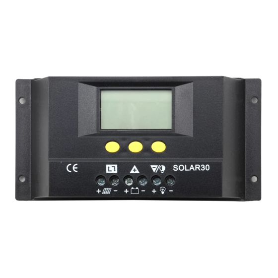
1. Product Introduction
This controller is an intelligent and multifunctional solar charge controller. These
serial products adopt customized LCD display screens, which make operations
on the interface rather convenient. All of the controlling parameters can be reset
to satisfy user needs. This controller has the following features:
• Visual LCD graphic symbol
• Brief key operation
• Grade auto-switch of system voltage
• Intelligent PWM Charging Mode
• Auto temperature compensation
• Adjustable charging & discharging parameter
• Settable working modes of loads
• Accumulative function of charging &
discharging AH
• Protection for battery back discharging
• Protection for battery low voltage
• Overloading & short-circuit protection
• Battery reversed protection
• Delayed auto restart after overloading
protection
2. Installation Explanation
Prepare the related tools and cables. Renogy suggests you choose the
appropriate cables to ensure the current density < 4 A/mm
reducing cable voltage drop. Recommendation: 30A using AWG 8 cable, or 50A
using AWG 6 cable.
1. Check whether the place of installation accords with the relative safety
rules. Please avoid installing and using the controller under the following
conditions: wet places, dusty places, or places with flammable and
explosive gases.
2. Install the controller at the vertical plane. Please refer to chapter 5 for
more detailed information about the required spacing between installing
holes. In order for the controller to have good thermal dissipation, please
spare 10cm above and below the controller.
30A PWM Solar Charge Controller with LCD
Model: PWM30CC-LCD
2
, which is good for
Advertisement
Table of Contents

Related Manuals for Renogy PWM30CC-LCD


Summary of Contents for Renogy PWM30CC-LCD
- Page 1 • Delayed auto restart after overloading protection 2. Installation Explanation Prepare the related tools and cables. Renogy suggests you choose the appropriate cables to ensure the current density < 4 A/mm , which is good for reducing cable voltage drop. Recommendation: 30A using AWG 8 cable, or 50A using AWG 6 cable.
- Page 2 3. As shown in the figure to the right, connect the loads, battery, and solar panels with the controller in proper order. Pay close attention when connecting the loads, battery, and solar panels, to ensure the job is done correctly. 4.
- Page 3 Load light control Load timing control Stop charge for battery Charging battery at full speed Float charging Normal working state Abnormal working state Battery capacity display Battery icon TABLE 3.1 LCD graphic symbols description Explanation of Buttons Interfaces circular toggling button: Use of this button can realize (show/create) the toggling circularly among the interfaces.
- Page 4 Parameter Review and Setting After the controller properly electrifies, it will enter the battery voltage onto the displaying interface. This interface is the main interface of the controller. Press button to go through the interfaces of the following parameters. If the interface can be reset, press button for at least 5 seconds (>5 seconds, and the number on the interface starts to flicker), then it will enter into the setting...
- Page 5 As shown in the figure to the right, the displayed number is the load current. 3.6 Reviewing and Clearing Accumulative, Generated Ah of Solar Panels As shown in the figure to the right, the displayed number is that of the accumulative, generating AH of the solar panels.
- Page 6 3.9 Reviewing and Setting Recovering Voltage for Voltage Condition As shown in the figure to the right, the displayed number is the recovery number. After the controller enters into a low voltage protection state, and when the battery voltage recovers to be higher than the recovering voltage, the controller will...
- Page 7 At this interface, press for greater than 5 seconds (>5 seconds). The number will start to flicker, which means the controller enters into the interface to set the load modes. Use buttons to adjust this parameter. After finishing this set-up, press for greater than 5 seconds (>5 seconds) to exit this interface and the controller can store this setting number.
- Page 8 Please restart the controller four times. Other exceptional conditions: Please contact the distributor or manufacturer. Charge Controller Specifications Electrical Characteristics Parameter PWM30CC-LCD Rated Working Voltage 12V/24V Rated Working Current Solar Input Voltage ≤48V Float Charging Voltage (adjustable) 13.8V/27.6V...
Need help?
Do you have a question about the PWM30CC-LCD and is the answer not in the manual?
Questions and answers