
Related Manuals for Renogy RIV1210PU-126


Summary of Contents for Renogy RIV1210PU-126
- Page 1 Renogy Pure Sine Wave Inverter with Transfer Switch 12V 1000W/2000W/3000W RIV1210PU-126/RIV1220PU-126/RIV1230PU-126 VERSION A0 USER MANUAL...
- Page 3 Renogy is not responsible or liable for any failure, damage, or injury resulting from repair attempts by unqualified personnel, improper installation, or inappropriate operation.
-
Page 4: Table Of Contents
What’s In the Box?..........................2 Required Tools & Accessories ......................2 Get to Know Renogy 12V 1000W Pure Sine Wave Inverter ............3 Get to Know Renogy 12V 2000W Pure Sine Wave Inverter ............4 Get to Know Renogy 12V 3000W Pure Sine Wave Inverter ............5 Part Description .......................... - Page 5 Renogy Support ..........................24 FCC Statement ..........................25 FCC Radiation Exposure Statement .....................25...
-
Page 6: Symbols Used
NOTE: Indicates an important step or tip for optimal performance. Introduction Renogy 12V 1000W/2000W/3000W Pure Sine Wave Inverter with Transfer Switch is ideal for a wide range of off-grid applications, including vans, semi-trucks, fifth wheels, cabins, and remote locations that require reliable power sources. The inverter converts DC Power stored in batteries into usable AC Power for appliances. -
Page 7: What's In The Box
What’s In the Box? Renogy Pure Sine Wave Inverter with Transfer Switch 12V 1000W/2000W/3000W RIV1210PU-126/RIV1220PU-126/RIV1230PU-126 VERSION A0 Renogy 12V 1000W/2000W/3000W Pure Sine Wave Inverter with Transfer Switch × 1 USER MANUAL User Manual × 1 Cables (3ft) × 2 (only 1000W/2000W inverter) -
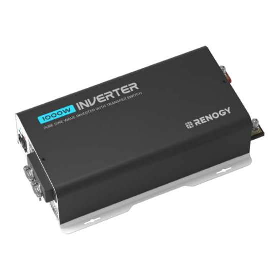
Page 8: Get To Know Renogy 12V 1000W Pure Sine Wave Inverter
Get to Know Renogy 12V 1000W Pure Sine Wave Inverter █ AC Side View GFCI LED Indicator Fault LED Indicator AC Input and Power LED Indicator High Output AC Terminals USB Power Port ON/OFF/REM Switch Remote Control Terminal AC Output Frequency... -
Page 9: Get To Know Renogy 12V 2000W Pure Sine Wave Inverter
Get to Know Renogy 12V 2000W Pure Sine Wave Inverter █ AC Side View GFCI LED Indicator Fault LED Indicator Power LED Indicator AC Input and High Output AC Terminals USB Power Port ON/OFF/REM Switch Remote Control Terminal AC Output Frequency... -
Page 10: Get To Know Renogy 12V 3000W Pure Sine Wave Inverter
Get to Know Renogy 12V 3000W Pure Sine Wave Inverter █ AC Side View GFCI LED Indicator Fault LED Indicator Power LED Indicator AC Input and High Output AC Terminals USB Power Port ON/OFF/REM Switch Remote Control Terminal AC Output Frequency... -
Page 11: Part Description
AC Outlets 120V AC, 50/60 Hz. z Up to 10A x 2 for Renogy 12V 1000W Pure Sine Wave Inverter z Up to 16A x 2 for Renogy 12V 2000W Pure Sine Wave Inverter z Up to 16A x 3 for Renogy 12V 3000W Pure Sine Wave Inverter USB Power Port Supplies 5V/2.1A for charging tablets, smartphones, and other small... -
Page 12: How To Properly Install Cable Clamps
High Output AC Terminals Connect to 120V AC devices operating at higher than 10A/20A/30A or distributed wiring with multiple AC outlets. Remove the two screws on the protective cover to access the terminals. Terminal layout (facing the front panel): z Left: Ground (G) z Middle: Live (L) z Right: Neutral (N) AC Input Terminals... -
Page 13: System Setup
System Setup System Wiring Starter Battery Solar Charge Panel Controller Solar Panel Fuse Battery Battery Fuse Fuse Battery Battery Fuse Fuse Battery Charger Battery Grid Power Inverter Loads Positive (DC) Negative (DC) The wiring diagram only shows the key components in a typical DC-coupled off-grid energy storage system for the illustrative purpose. -
Page 14: Inverter Wiring
Inverter Wiring The wiring diagram provided in this section is tailored for a 1000W inverter model. Similar wiring rules apply to other models. █ AC Side View Wired Remote Loads Ground Fault Control (USB) AC Loads Circuit Interrupter AC Loads Grid Power (GFCI) Single-... -
Page 15: Size A Battery Bank
Size a Battery Bank Battery types and capacity relate to the overall inverter performance. To size a proper battery bank, you need to identify the loads that you will be utilizing, as well as an estimate duration (hours/day) you will be using the load. The inverter is only compatible with 12V battery banks, and oversizing should be considered due to efficiency losses. -
Page 16: Step 2. Plan A Mounting Site
Step 2. Plan a Mounting Site Follow the guidelines below: z Cool, dry, and well-ventilated area The inverter must be installed in a site where the fans are not blocked or where they are not hit directly by the sun. The site should be free of any kind of moisture with a clearance of at least 10 inches around the inverter for adequate ventilation. -
Page 17: Step 3. Grounding
Step 3. Grounding Grounding is highly recommended for both when using the inverter in a mobile application, such as an RV, or in a building. If available, the chassis ground lug should be connected to a ground point such as a vehicle chassis or boat grounding system. In fixed locations, connect the ground lug to earth ground. - Page 18 For your safety, it is recommended that you should use a battery fuse on the positive end. Model RIV1210PU-126 RIV1220PU-126 RIV1230PU-126 Continuous Output Power 1000W 2000W 3000W Battery Fuse 150A 250A 400A Step 1: On the AC side, set the ON/OFF Switch to the OFF position.
-
Page 19: Step 5. Ac Output Wiring
Step 5. AC Output Wiring Recommended Ground-Fault Circuit Interrupter (GFCI) A ground-fault circuit interrupter, or GFCI, is a device that helps protect people from electric shocks by de-energizing a circuit or portion of a circuit within an established period of time when a current to ground exceeds some predetermined value that is less than that required to operate the overcurrent device (circuit breaker or fuse) of the supply circuit. -
Page 20: Step 6. Ac Input Wiring (Optional)
Ground Fault Circuit Interrupter (GFCI) For details on how to connect loads and the inverter to the GFCI, read the user manual of the specific GFCI. Step 6. AC Input Wiring (Optional) Utilizing the built-in transfer switch, this inverter seamlessly switches to grid power, bypassing the inverter when it’s available, thereby directly supplying the load with grid power. -
Page 21: Power On/Off
Power On/Off █ Operations on Inverter After proper battery and AC load connections, you can operate the inverter. 1. On the AC side, rock the ON/OFF Switch to the ON position. 2. The inverter is operating normally. When finishing using the inverter, power off the AC loads first, and then rock the ON/OFF Switch to the OFF position. -
Page 22: N-G Bonding Relay
Step 2: Rock the ON/OFF Switch to the REM position, and you can power on/off the inverter via the Wired Remote Control. The inverter is off. The inverter is on. RMS-P2 N-G Bonding Relay The inverter is equipped with a Neutral to Ground (N-G) bonding relay that ensures that either the neutral in or out contact of the RV is always grounded. -
Page 23: Monitor The Inverter
In scenarios where the N-G bonding relay is disabled, the N-G bonding relay connects to the ground contact of the inverter only. You have the option to manually enable or disable the N-G Bonding Relay. Enabled Disable The N-G bonding relay must be enabled when the battery supplies the connected loads because the GFCI will be unavailable if the N-G bonding relay is disabled. -
Page 24: Short-Range Monitoring Via Dc Home App
Wireless Long-Range Monitoring If long-range communication and programming are required, connect the inverter to Renogy ONE (sold separately) through Bluetooth, and the Renogy ONE to the DC Home app through Wi-Fi. Recommended Components *RENOGY ONE Core or Renogy ONE M1 Components marked with “*”... -
Page 25: Led Overview & Troubleshooting
If it stays off, this suggests a current leakage issue with one of the appliances. If the LED remains on, kindly reach out to Renogy via renogy.com/ contact-us for further assistance. No sound and Disconnect appliances, and use the... -
Page 26: Pure Sine Wave
Overload protection seconds (manual restart required if beeping sound automated recovery fails). For further assitance, contact Renogy technical support service at https:/ /www.renogy. com/contact-us. Pure Sine Wave The inverter outputs a pure sine wave similar to the waveform of the grid power. In a pure sine wave, the voltage rises and falls in a smooth fashion with very low harmonic distortion and cleaner utility-like power. -
Page 27: Specifications
Specifications General Data Model RIV1210PU-126 RIV1220PU-126 RIV1230PU-126 Output Waveform Pure Sine Wave 2 x AC sockets 2 x AC sockets 3 x AC sockets AC Terminals 1 x AC high-output 1 x AC high-output 1 x AC high-output terminal block... -
Page 28: General Safety Information
Maximum Continuous 105A 210A 310A Battery Output Current Inverter Efficiency 92%, MAX Full Load Efficiency Power Consumption < 12W < 18W < 18W Battery Overoltage 16.0V (±0.3V) DC Shutdown Battery Low Voltage Alarm 11.0V (±0.3V) DC Battery Low Voltage 10.5V (±0.3V) DC Shutdown Wired Remote Data Front Plate Dimensions... - Page 29 Questionnaire Investigation To explore more possibilities of solar systems, visit Renogy Learning Center at: renogy.com/learning-center For technical questions about your product in the U.S., contact the Renogy technical support team through: renogy.com/contact-us 1(909)2877111 For technical support outside the U.S., visit the local website below:...
- Page 30 FCC Statement This device complies with Part 15 of the FCC Rules. Operation is subject to the following two conditions: (1) This device may not cause harmful interference. (2) This device must accept any interference received, including interference that may cause undesired operation.
- Page 32 Save 105 gallons of water from being consumed Renogy Power PLUS Renogy Power Plus allows you to stay in the loop with upcoming solar energy innovations, share your experiences with your solar energy journey, and connect with like-minded people who are changing the world in the Renogy Power Plus community.
Need help?
Do you have a question about the RIV1210PU-126 and is the answer not in the manual?
Questions and answers