Table of Contents
Advertisement
Advertisement
Table of Contents

Related Manuals for Renogy PCL Series


Summary of Contents for Renogy PCL Series
- Page 1 SERIES 2000W/3000W Pure Sine Wave Inverter & Charger Version 1.1...
-
Page 2: Table Of Contents
CONTENTS General Information Product Overview Identification of Parts Dimensions Included Components Installation Location Recommendations Sizing A Battery Bank Grounding DC WIRING AC WIRING Automatic Neutral-to-Ground Bond Switching Automatic Transfer Relay Auto Generator Start Operation Fan Operation Main Menu 05 Setup Battery Type 05 Custom Battery Type /User Mode Display Panel LCD Display Icons and Behaviors... - Page 3 Important Safety Instructions Please save these instructions. This manual contains important safety, installation, and operating instructions for the inverter. The following symbols are used throughout the manual: Indicates a potentially dangerous condition. Use extreme caution WARNING when performing this task. Indicates a critical procedure for safe and proper operation of the inverter.
- Page 4 Battery Safety Do NOT let the positive (+) and negative (-) terminals of the battery touch each other. Use sealed Lead-Acid, Flooded, Gel, AGM, Lithium or Calcium batteries which must be deep cycle. Explosive battery gases may be present while charging. Be certain there is enough ventilation to release the gases.
-
Page 5: General Information
General Information The Renogy PCL series inverter-chargers combine an inverter and battery charger with an automatic transfer switch into one complete system. Featuring a 3-stage battery charging mode when connected to utility AC power, the PCL series inverter-charger can meet powerful demand needs as well as charge your battery bank. -
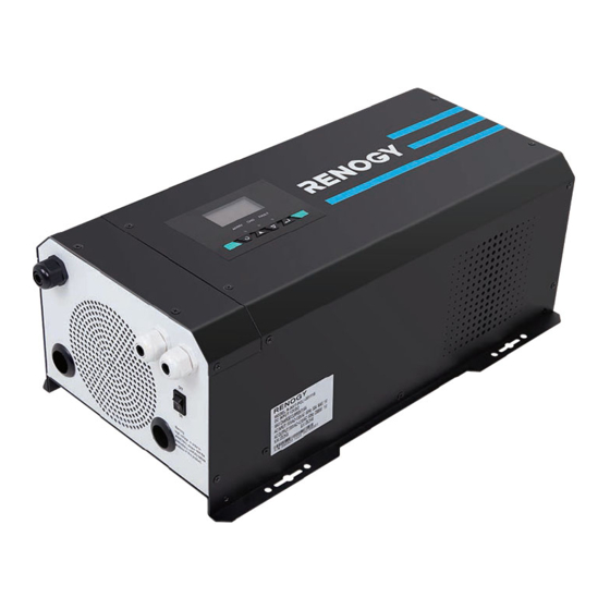
Page 6: Product Overview
Product Overview Identification of Parts Top view AC Input Cable Entry AC Output Cable Entry Wired Remote Control Cable Entry LCD Panel and Buttons Mounting Holes... - Page 7 Left View (Covered) Left View (Uncovered) Main ON/OFF Switch: This is a simple Rj45 Port for Future Development ON/OFF switch to be able to control the AC Output Terminal Block inverter with the plate in place. The wiring is connected to the Terminal Block AC Input Terminal Block on the inside of the plate seen in 13.
-
Page 8: Dimensions
Included Components Battery Temperature Sensor (BTS) Renogy inverter chargers come equipped with a battery temperature sensor that will help prolong the battery life. The battery sensor allows the inverter charger to continuously adjust the charging voltage based on the battery temperature. The inverter charger will compensate charging with a factor of -0.5mV/C◦... - Page 9 Wired Remote Control The wire remoted control for the inverter chargers gives users the opportunity to power on/off the inverter from a distance. Giving you approximately 16.4ft of distance, simply connect the cable to the RJ11 port on the PCL unit. Make sure both the PCL inverter model and the wired remote are both in the off position.
-
Page 10: Installation
Installation Make sure inverter is in the off position before connecting anything. WARNING Do not over-torque or over tighten the terminals. This could potentially CAUTION damage the unit. Refer to the technical specifications for max wire sizes on the controller CAUTION and for the maximum amperage going through wires. -
Page 11: Sizing A Battery Bank
Utilize the formula Watts = Volts * Amps Determine Amps used for how many hours – Amp-hour (Ah) For this Renogy inverter, the battery bank will be 12 volts direct current (12 VDC) Example A Microwave oven... -
Page 12: Dc Wiring
DC WIRING The Renogy Pure Sine Wave Inverters are suitable for 12V battery bank systems ONLY. WARNING Not following the minimum DC requirement will cause irreversible damage to the unit. Be careful of the positive and negative poles. Reversing the poles might cause CAUTION permanent damage to the inverter. -
Page 13: Ac Wiring
When installing DC cables, the following are recommendations: Battery positive and negative cables should be as close to the battery as possible to minimize voltage loss and other possible effects. Tie, tape, or twist cables together to reduce self-inductance. Install all overcurrent devices on the positive cable. Model Recommended Fusing Recommended Wire Sizing... -
Page 14: Automatic Neutral-To-Ground Bond Switching
Be careful of the positive and negative poles. Reversing the poles might cause CAUTION permanent damage to the inverter. It will surely blow the internal fuse. Damage to the Renogy inverters due to reverse polarity is NOT covered by warranty. NOTE... - Page 15 The input terminals of the inverters have large capacitors connected to them. Once a NOTE positive and negative wire are connected to the terminals, it will complete the circuit, and commence drawing a heavy current momentarily. As a result, there may be a sparking occurring even if the inverter is in the off position.
-
Page 16: Automatic Transfer Relay
Automatic Transfer Relay The PCL inverter chargers are equipped with a 30A transfer relay switch that switches between Inverter and Standby mode depending on availability of AC input power. If AC is present, the transfer relay bypasses up to 30A of the incoming AC power through the inverter to power the AC loads on the inverter’s output. -
Page 17: Operation
Operation Upon successful connection of a 12V deep cycle battery bank, flip the inverter power to the ON position. Upon successful connection of a 12V deep cycle battery bank, flip the inverter power NOTE to the ON position. The unit may also be powered on by the wired remote control. NOTE Function Keys Exit setting mode, go back to main menu... - Page 18 INPUT OUTPUT 100% Input Volts AC / Output Volts AC BATT OUTPUT 100% Battery Volts DC / Load Volts AC BATT OUTPUT 100% Battery Volts DC / Output Watts...
- Page 19 BATT OUTPUT 100% Battery Volts DC / Output Load % BATT OUTPUT 100% Battery Volts DC / Output Frequency INPUT OUTPUT 100% Input Frequency / Output Volts AC...
- Page 20 INPUT 100% Input Volts AC / Input Amps TEMP OUTPUT 100% Inverter Temperature Celsius / Output Volts AC 100% Inverter Version Number...
-
Page 21: Setup Battery Type
Use the arrow keys to go to Program 05. Use the following table to set the appropriate battery type based on the boost voltage and float voltage that has been preset. The PCL series is only compatible with 12V battery banks. NOTE... -
Page 22: Custom Battery Type /User Mode
05 Custom Battery Type /User Mode If the preset battery options are not compatible with your system, you will need to custom the charging by following the next steps. 1. Set the battery type to b-0. By default this unit is preset to boost at 14.3V and Float at 13.7V. -
Page 23: Display Panel
b.Once finished, go to Program 27 to set the battery low voltage recovery charge. This will be the voltage that the battery discharges to before the inverter-charger charges the battery to the predetermined maximum charging voltage Program Parameter Description Number Setting Battery low voltage open If User-defined is selected in program 94,this program can be set... -
Page 24: Lcd Display Icons And Behaviors
LED Indicator Parameter Output is powered by an AC source in line Solid AC/INV Green Output is powered by battery or in invert mode Flashing Battery is fully charged Solid Green Flashing Battery is charging Fault occurred Solid FAULT Warning conditions has occurred Flashing Function Keys Exit setting mode, go back... - Page 25 INPUTBATT ERROR ERROR OUTPUTBATTLOAD CHARGING <12.0V 12.0.V-12.5V 12.5V-13.0V >13.0V...
- Page 26 <10.3V 10.3V 10.8V 10.8V~11.3V >11.3V <10.9V 10.9V 11.4V 10.9V~11.9V >11.9V <11.2V 11.2V 11.7V 11.7V~12.2V >12.2V OVER LOAD Indicates the load level by 0-24%, 25-49%, 50-74% and 75-100%. 100% 0%-24% 25%-49% 50%-74% 75%-100% Indicates unit is connected to shore power BYPASS...
-
Page 27: Programmable Features
Programmable Features The PCL inverter charger series is fully programmable. You may change the respective parameter by going to the Program Number listed below Function Keys Exit setting mode, go back to main menu Cycle through the menu Cycle through the menu 1. -
Page 28: Ac Input Voltage Range
The following steps need to be taken to properly set the inverter charger to Battery Priority (SbU) 1. Press and hold the Enter key to enter the setting screen. 2. Press the down arrow key until setting 01 is shown. Press and hold the Enter key until the setting starts flashing, press the up or down arrow key to select SbU. -
Page 29: Power Saving Mode
04 Power Saving Mode Power saver function is designed to conserve battery power when AC power is not or rarely required by the loads. In this mode, the inverter pulses the AC output looking for an AC load (i.e., electrical appliance). Whenever an AC load (greater than 50 watts) is turned on, the inverter recognizes the need for power and automatically starts inverting and output goes to full voltage. -
Page 30: Maximum Utility Charging
11 Maximum Utility Charging The PCL inverter chargers can operate like battery chargers converting incoming AC power into DC recharging power. The 2000W has a 65A max while the 3000W has a 75A max adjustable battery charging. The default is the maximum value (65A-2KW, 75A-3KW), with a 5A minimum. -
Page 31: Screen Mode
Alarm Parameters: Inverter Charger Failure (Low-voltage The buzzer will keep beeping Shutdown, High-voltage Shutdown, Overheating Protection, Overload Protection) Pressing Function Keys The buzzer will beep for 0.5s Working Mode Transfer The buzzer will beep for 0.5s Overheating/Overload Alarm The buzzer will beep for 0.3s every 1s Low-voltage/High-voltage Alarm The buzzer will beep for 0.2s every 0.5s 19 Screen Mode... -
Page 32: Record Fault Code
25 Record Fault Code The PCL inverter will demonstrate the fault code. 26 Boost Charging Refer to Program 5 for modifying this setting. This setting will not be modifiable if users choose a pre-set battery voltage. NOTE Bulk charging voltage(C.V If User-defined is selected in program94,this program can voltage) be set up. -
Page 33: Input Frequency Range
The default setting is 10.0V. Setting range is from 10.0V to 12.0V with increments of 0.1V. This setting must be at least 0.5V lower than setting #98 Low Battery Alarm. BATT 93 Input Frequency Range The factory default frequency for inverters is 60Hz. Normally, manufacturers build electrical devices for a certain amount of Current, Voltage and Hertz (Cycles) which is mentioned on the name plate. -
Page 34: Low Voltage Trip For Dry Contacts
When dry contact switch from NC to NO, battery voltage arrive to setting voltage, dry contact point switch to NC. This setting can not be than fast charge voltage.higher setting range is from 13.0V to 15.5V for 12V Increment of each click is 0.1V for 12V BATT 96 Low Voltage Trip for Dry Contacts... -
Page 35: Low Battery Voltage Alarm
98 Low Battery Voltage Alarm Users can select to have the PCL inverter-charger sound an alarm at a programmable battery voltage. This will need to be a higher value than Program 29 Low DC Cut-off Voltage as it will warn users that the battery is discharging before ultimately disconnecting. The default is 10.5V. -
Page 36: Battery Charging Stages
Battery Charging Stages Bulk Stage: The charger will supply constant current until the battery voltage reaches the boost voltage. The software will calculate the time charging began up until the battery voltage reaches 0.3V below the boost voltage. It uses this time to as T0 and T0×10 = T1. Boost Stage: The charger will supply constant voltage and reduce the current slowly through this stage. -
Page 37: Fault / Warning Codes
Fault / Warning Codes The following fault codes will have a caution symbol when experiencing the fault NOTE Warning Code Warning Event Icon On Battery over voltage Battery low voltage Inverter over temperature Inverter overload Transformer phase reversal Frequency is out of range The following will experience an error display as well as the fault code NOTE Heat sink over temperature... -
Page 38: Technical Specifications
Technical Specifications Model R-INVT-PCL1-20111S R-INVT-PCL1-30111S Inverter Specifications Rated Output Power 2000W 3000W Surge Power (1 second) 6000W 9000W Surge Power (3 seconds) 3000W 4500W Surge Power (10 seconds) 2400W 3600W Nominal output Voltage RMS 120 VAC ( 100 ~ 120VAC, 5V intervals 50HZ ±... - Page 39 Model R-INVT-PCL1-20111S R-INVT-PCL1-30111S Transfer Switch Specifications Transfer Time ~ 10ms Line Mode Efficiency > 95% Transfer Relay Rating 30A Maximum Bypass General Specifications Battery Types GEL, AGM, SLA, FLD, CAL, LI, USER Operating Temperature Range 0~40°C/0~104°F Storage Temperature -30~70°C/-22~158°F Humidity 0% ~ 95% Noise <50dB...
- Page 40 RENOGY.COM Renogy reserves the right to change the contents of this manual without notice. 2775 E Philadelphia St, Ontario, CA 91761, USA 909-287-7111 www.renogy.com support@renogy.com 苏州高新区科技城培源路1号5号楼-4 400-6636-695 https://www.renogy.cn support@renogy.cn https://www.renogy.jp supportjp@renogy.com https://ca.renogy.com supportca@renogy.com https://au.renogy.com supportau@renogy.com https://uk.renogy.com supportuk@renogy.com https://de.renogy.com supportde@renogy.com...
Need help?
Do you have a question about the PCL Series and is the answer not in the manual?
Questions and answers