
Related Manuals for Renogy 500W


Summary of Contents for Renogy 500W
- Page 1 Battery Power Inverters Renogy 500W | 1000W | 2000W Pure Sine Wave Inverter Manual 2775 E. Philadelphia St., Ontario, CA 91761 1-800-330-8678 Version 1.1...
-
Page 2: Important Safety Instructions
Important Safety Instructions Please save these instructions. This manual contains important safety, installation, and operating instructions for the inverter. The following symbols are used throughout the manual: WARNING: Indicates a potentially dangerous condition. Use extreme caution when performing this task. CAUTION: Indicates a critical procedure for safe and proper operation of the inverter. - Page 3 Battery Safety Do let the positive (+) and negative (-) terminals of the battery touch each other. Use only sealed lead-acid, flooded, or gel batteries which must be deep cycle. Explosive battery gases may be present while charging. Be certain there is enough ventilation to release the gases.
-
Page 4: Table Of Contents
Table of Contents General Information ...................... 5 Included Components ....................6 Identification of Parts (AC Side)................... 7 Identification of Parts (DC Side)................... 9 Installation ........................10 Location Recommendations ................... 10 Sizing a Battery Bank ....................11 Grounding ........................ 12 DC Side Connection ....................13 Operation ........................ -
Page 5: General Information
A remote for powering the inverter loads on or off (For select models only) Pure Sine Wave The Renogy Power Inverters output a pure sine wave similar to the waveform of the grid power. In a pure sine wave, the voltage rises and falls in a smooth fashion with very low harmonic distortion and cleaner utility-like power. -
Page 6: Included Components
Included Components The Renogy Pure Sine Wave Battery Inverters will be shipped with inverter cables and select models will include a key chain remote for powering the inverter on or off. Inverter Type Cables Gauge RNG-500W 6 AWG 1 red inverter cable and 1... -
Page 7: Identification Of Parts (Ac Side)
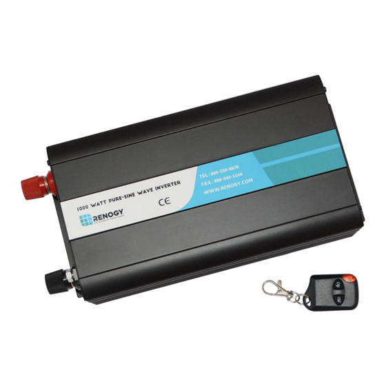
The remote works for a maximum distance of 170 feet from the inverter’s location and it includes a clip for easy attaching. Wireless remote with clip Identification of Parts (AC Side) Figure 1: 500W Inverter... - Page 8 Figure 2: 1000W Inverter Figure 3: 2000W Inverter Key Parts 1. Ventilation Holes 2. AC Output socket(s) 3. Power Indicator 4. Over-heat / Low-voltage protection indicator 5. Over-voltage protection indicator 6. Over-load protection indicator 7. Short-circuit indicator 8. USB output port (5V, 2A) 9.
-
Page 9: Identification Of Parts (Dc Side)
Identification of Parts (DC Side) Figure 4: 500W Inverter Figure 5: 1000W Inverter... -
Page 10: Installation
Figure 6: 2000W Inverter Key Parts 1. Positive Terminal Connection(s) 2. Ventilation Fan(s) 3. Grounding Bolt 4. Negative Terminal Connection(s) Installation WARNING: Make sure inverter is in the off position before connecting anything. CAUTION: Do not over-torque or over tighten the terminals. This could potentially damage the unit CAUTION: Refer to the technical specifications for max wire sizes on the controller and for the maximum amperage going through wires. -
Page 11: Sizing A Battery Bank
Ensure installation follows the following guidelines: 1. Cool, dry, well-ventilated area—Heat is the worst enemy for electronic equipment. Inverters must be in an area where the fans are not blocked or where they are not hit directly by the sun. They should be in an area free of any kind of moisture and allow for clearance of at least 10”... -
Page 12: Grounding
*For this Renogy inverter, the battery bank will be 12 volts direct current (12 VDC) Example 700 Watts to run microwave using the batteries as if it was a 12VDC microwave requires 58 Amps A Microwave = 700 Watts 700 Watts / 12 Volts = 58 Amps... -
Page 13: Dc Side Connection
This serves the purpose of splitting the potentially high amperages and protecting the wires. NOTE: The 500W inverter is used as the example in the wiring schematics. The same principles apply to the 1000W and 2000W inverters. 1. Flip inverter power to OFF position (on AC side) - Page 14 2. Unscrew inverter terminals and connect battery connections. Then tighten.
-
Page 15: Operation
Simply be within a 170 foot radius of the inverter and press the off or on button. NOTE: The wireless remote is not included in the 500W inverter models. -
Page 16: Usb Operation
USB Operation The Renogy inverters are equipped with a unique USB feature where the user is able to plug their USB devices for charging purposes. This feature is a simple “plug and play”. NOTE: USB operation is not compatible with the Apple Lightning Connector. -
Page 17: Inverter Troubleshooting
If the inverter experiences an internal Short Circuit Indicator short circuit, it will sound the alarm and (AUDIBLE ALARM) turn on the red indicator. Inverter Troubleshooting Indicator Troubleshoot Use a multi-meter to check the voltage of the battery. Make sure the battery voltage is not below the rated specification of the inverter. - Page 18 A short might occur down the DC line connecting to the inverter. Check the battery connections going to the inverter and ensure that there is continuity. In the event that there is an in-line fuse installed, check to make sure the fuse has not blown.
-
Page 19: External Fusing
When the inverter is switched on, the circuitry inside is activated. Even if there is no load on the AC side of the inverter, users will experience a small amount of current Idle draw from inverter draw to keep the circuitry within the inverter ready to power. -
Page 20: Technical Specifications
Technical Specifications Model RNG-500W RNG-1000W RNG-2000W Rated Power 500 W 1000 W 2000 W Surge Power 1000 W 2000 W 4000 W Rated Voltage 12 VDC Rated Voltage 11 V – 15V Range DC ≥ 10V ± 0.5V Input Voltage Over-Voltage 16V ±...
Need help?
Do you have a question about the 500W and is the answer not in the manual?
Questions and answers