
Related Manuals for GEA Aseptomag DK


Summary of Contents for GEA Aseptomag DK
- Page 1 Aseptic Valves ® GEA Aseptomag double chamber valve type DK Operating instruction (Translation from the original language) 430BAL012555EN_3...
- Page 2 LEGAL NOTICE Word marks ® ® Aseptomag and TEFASEP are registered trademarks of GEA Aseptomag AG and may not be used without the permission of GEA Aseptomag AG. ® T.VIS is a protected trademark of GEA Tuchenhagen GmbH. 430BAL012555EN_3 27.08.2024...
-
Page 3: Table Of Contents
TABLE OF CONTENTS General Information Information on the Document 1.1.1 Binding Character of These Operating Instructions 1.1.2 Notes on the Illustrations 1.1.3 Symbols and Highlighting Manufacturer address Customer service EC Declaration of Incorporation Safety Intended use 2.1.1 Requirements for operation 2.1.2 Pressure equipment directive 2.1.3... - Page 4 10.1 Safety instructions 10.2 Inspections 10.2.1 Bellows 10.2.2 Piston rod seal 10.2.3 Pneumatic connections 10.2.4 Electrical connections 10.3 Maintenance intervals 10.4 List of tools 10.5 Prior to disassembly 10.6 Disassembling and Assembling the Valve 10.6.1 Removing the valve 10.6.2 Installing the valve 10.6.3 Torques for clamp 10.7...
- Page 5 12.1 Safety instructions 12.2 Disposal 12.2.1 General notes Appendix 13.1 Lists 13.1.1 Abbreviations and terms 430BAL012555EN_3 27.08.2024...
- Page 6 430BAL012555EN_3 27.08.2024...
-
Page 7: General Information
General Information Information on the Document General Information Information on the Document The present Operating Instructions are part of the user information for the product. The Operating Instructions contain all the information you need to transport, install, commission, operate and carry out maintenance for the product. 1.1.1 Binding Character of These Operating Instructions These Operating Instructions contain the manufacturer's instructions to the... -
Page 8: Manufacturer Address
Result of the previous operation. ® The operation is complete, the goal has been achieved. Hint! Further useful information. Manufacturer address GEA Aseptomag AG Industrie Neuhof 28 CH-3422 Kirchberg Customer service Phone: +41 (0)34 426 29 29 Fax: +41 (0)34 426 29 28 service.aseptomag@gea.com... -
Page 9: Ec Declaration Of Incorporation
Teamleader Product Development GEA Aseptomag AG Flow Components – Aseptic Valves GEA Aseptomag AG Tel. +41 34 426 29 29 · Fax +41 34 426 29 28 · gea.com Industrie Neuhof 28, CH-3422 Kirchberg Seite 1 von 1 430BAL012555EN_3 27.08.2024... -
Page 10: Safety
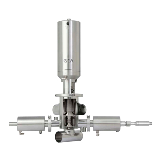
Safety Intended use Safety Intended use Aseptic double chamber valves of type DK are mix-proof stroke valves for aseptic process systems and permit the safe separation of incompatible media. The media separation is done via the integrated sterile chamber (ISB), which is separated hermetically from the atmosphere with a seal each to both product lines and via two side valves (inlet and outlet). -
Page 11: Requirements For Operation
The valve is a piece of pressure equipment (without safety function) as defined in the Pressure Equipment Directive: Directive 2014/68/EG. It is classified according to Annex II, article 4, section 3. In the event of any deviations, GEA Aseptomag AG will supply a specific Declaration of Conformity. -
Page 12: Improper Operating Conditions
Safety Operator’s Duty of Care ® Aseptomag valve technology can also be used in ATEX protected areas. However, the suitability of the component must be checked under consideration of the respective conditions. Additional information will be made available upon request. 2.1.4 Improper operating conditions The operational reliability of the valve cannot be ensured under improper... -
Page 13: Subsequent Changes
EC Machinery Directive on your own. In general, only original spare parts supplied by GEA Aseptomag AG should be fitted. This ensures the reliable and economical operation of the valve. -
Page 14: Environmental Protection
Safety Supplementary Regulations 2.4.2 Environmental Protection Harm to the environment can be avoided by safety-conscious and proactive behaviour of the staff. For environmental protection the following principles apply: • Substances harmful to the environment must not be discharged into the ground or the sewage system. - Page 15 Safety Qualification of Staff Only allow specially trained staff to carry out any work on explosion-protected equipment. When working on explosion-protected equipment observe the standards DIN EN 60079-14 for gases and DIN EN 50281-1-2 for dusts. The following minimum qualifications are required: •...
-
Page 16: Safety Equipment
Safety Safety equipment User groups Staff Qualifications Operating staff Adequate instruction and sound knowledge in the following areas: • Function of the valve • Valve operating sequences • What to do in case of an emergency • Lines of authority and responsibilities with respect to the task Maintenance staff Adequate instruction as well as sound knowledge of the design and function of the valve. -
Page 17: Residual Dangers
Safety Residual dangers Residual dangers Dangerous situations can be avoided by safety-conscious and proactive behaviour of the personnel and by wearing personal protective equipment. Residual dangers on the valve and measures Danger Cause Measure Danger to life Inadvertent Effectively disconnect all components, effectively prevent switch-on of the switch-on. -
Page 18: Danger Zones
Safety Danger zones Danger zones Fig.5: Danger zone at the valve Please observe the following notes: • In the event of malfunctions, shut down the valve (disconnect from the power and air supply) and secure it against being used. • Never reach into the motor stool (1) or the valve housing (2) when the valve is switching. -
Page 19: Description
Description Design of the Valve Description Design of the Valve Fig.6: Main components on the valve Designation Housing Internal assembly Valve seat A Valve seat B Actuator Clamp (safety device) Inlet valve (side valve) Outlet valve (side valve) Clamp to side valve (safety installation) Temperature sensor (optional) 430BAL012555EN_3 27.08.2024... -
Page 20: Valve Identification
Description Valve Identification Valve Identification Reference numbers from the following number systems are assigned to each part of components from GEA Aseptomag AG. The reference numbers can be used to clearly identify a component and its composition. Number Designation Description... - Page 21 Description Valve Identification Fig.7: Designations on the valve Example Position Details V50-1235 Valve Drawing number of valve housing housing 1.4435 TC 333937 Material and re-stamping details 0548 10 Valve Serial number of valve housing housing V-50-1004 Clamp Number of clamp drawing V-50-2245 Internal Drawing number of internal assembly...
- Page 22 Description Valve Identification Example Position Details PA60/25 DK OR NC PT Outlet valve Designation of actuator V25-3121 Number of actuator drawing 0813 10 Serial number of actuator V-15-1004 Number of clamp drawing TR31-K-Z-TT Temperature Type designation sensor 430BAL012555EN_3 27.08.2024...
-
Page 23: Sealing Concepts
Divisible valve disc, valve seat seal EPDM (form seal) Concept for hard sealing materials • Divisible valve disc • GEA Aseptomag option for seat A • For hard sealing materials like TEFASEP (TVT) • Additional elastomer O-ring behind the valve seat seal Fig.10:... - Page 24 Description Fig.11: "Divisible" version - for elastomer sealing materials 430BAL012555EN_3 27.08.2024...
-
Page 25: Transport And Storage
Transport and storage Storage conditions Transport and storage Storage conditions The valves, valve inserts or spare parts should be stored in a dry place, free of vibrations and dust, and protected from light. To avoid damage, leave the components in their original packaging if possible. If, during transport or storage, the valve is going to be exposed to temperatures ≤... -
Page 26: Technical Data
Technical data Technical data Technical data Technical data Operating data (for valve with sealing materials Tefasep and silicone) Max. operating temperature 150 °C (302 °F) Max. sterilisation temperature 160 °C (320 °F) for max. 30 min. Max. product pressure 6 bar (others on request) Max. - Page 27 Technical data Resistance of sealing materials All sealing materials in the product contact area are suitable for applications in the food industry. The durability of the sealing materials depends on the type, temperature and contact time of the conveyed media. The final assessment of the suitability of Product contact seals the material is therefore the sole responsibility of the plant operator, even if the materials meet all common guidelines of...
-
Page 28: Assembly And Installation
Assembly and installation Safety instructions Assembly and installation Safety instructions Dangerous situations during assembly can be avoided by safety-conscious and proactive behaviour of the staff. For installation, the following principles apply: • Only properly qualified staff is allowed to install, assemble and set the valve into operation. -
Page 29: Welding Post-Treatment
Assembly and installation Welding In a Valve with Pipe Connection Caution! Danger of injury due to spring force being released You can sustain injuries to your fingers when you put your hand into a valve if the valve has not been moved to the open position beforehand. ►... -
Page 30: Pneumatic Connections
Assembly and installation Pneumatic connections Pneumatic connections 6.4.1 Overview switching positions Fig.12: Air connections valve version EA Function Valve seat Air connection Open “A“ + “B“ "D" Ventilation (EA & AZ) “A“ "E" Ventilation (EA) “B“ "C" Control Side valve ®... -
Page 31: Establishing The Compressed Air Supply
Assembly and installation Electrical connections Air requirement for DK EA for spring-to-close actuators (NC) Air requirements [dm Nominal width of valve Actuator Total stroke Venting seat A Venting seat B DN100 / 4"OD PA180/100 EA PA255/125-150 DN125 17.0 14.0 Air requirement DK EA for actuators NC and NO of the side valve Valve associated side valve Nominal width... - Page 32 Assembly and installation Danger Live parts Electrical shock can result in serious personal injury or death. ► Only allow properly qualified staff to carry out work on the electrical equipment. ► Prior to establishing electrical connections check the maximum permissible operating voltage. Explosive gases or dusts An explosion can result in serious personal injury or death.
-
Page 33: Start-Up
Start-up Safety instructions Start-up Safety instructions Initial commissioning For initial commissioning, the following principles apply: • Take protective measures against dangerous contact voltages in accordance with pertinent regulations. • The valve must be completely assembled and correctly adjusted. All screw connections must be securely tightened. -
Page 34: Operation And Control
Operation and control Safety instructions Operation and control Safety instructions Dangerous situations during operation can be avoided by safety-conscious and proactive behaviour of the staff. For operation, the following principles apply: • Monitor the valve during the operation. • Safety devices must not be changed, removed or taken out of service. Check all safety devices at regular intervals. -
Page 35: Cleaning
Cleaning Cleaning Cleaning Cleaning The valve is suitable for CIP (Cleaning in Place); recommended cleaning speed in the valve is at least 2 m/s. All parts in contact with product must be cleaned at regular intervals. Always observe the safety data sheets issued by the cleaning agent manufacturers. Only use cleaning agents which do not cause damage to the seals and the inner parts of the valve. - Page 36 Cleaning The ultimate temperatures, chemicals, concentrations and contact time to be used must be determined by the plant operator along with its chemical supplier. 430BAL012555EN_3 27.08.2024...
-
Page 37: Maintenance
Maintenance Safety instructions Maintenance 10.1 Safety instructions Maintenance and repair Before carrying out maintenance and repair work on the component's electrical equipment, perform the following steps in accordance with the "5 safety rules": • Isolate from the power supply • Take appropriate measures to prevent switch on •... -
Page 38: Inspections
Maintenance Inspections • Disconnect all power and utility lines. • Markings, e.g. on lines, must not be removed. • Do not climb on the component. Use suitable access aids and working platforms. • Mark the lines (if unmarked) prior to disassembly to ensure they are not confused when re-assembling. -
Page 39: Maintenance Intervals
If information regarding the definition of practical-oriented maintenance intervals is not available or is insufficient, the guideline values listed in the "Maintenance" chapter can be referred. This information is based on empirical values for GEA Flow Components and relates to installations working in two-shift operation. - Page 40 Maintenance List of tools List of tools (in alphabetical order) Material Number Tool Figure Intended Purpose GEA Aseptomag AG Valves AZ & NC Pressurising tool AZ & 0980.50073 DN 125 S-12-0454 Inspection of metal DN 125" bellows Fig.15 Valves EA Pressurizing tool EA 0980.10060...
- Page 41 Maintenance List of tools List of tools (in alphabetical order) Material Number Tool Figure Intended Purpose GEA Aseptomag AG Jaw insert SW17 Side valve PA60 0980.50306 Fig.19 Pressure control valve Inspection of metal 9999.10090 bellows Ø 6 mm Fig.20 Flexible head spanner PA80-135 0980.10009...
- Page 42 Maintenance List of tools List of tools (in alphabetical order) Material Number Tool Figure Intended Purpose GEA Aseptomag AG Oven 0981.50016 Preheat hard valve (no microwave, seat seals S-12-0084 min. temp. 140 °C) Fig.24 Valves Hex socket key 0980.50121 DN 10 - DN 65...
- Page 43 Maintenance List of tools List of tools (in alphabetical order) Material Number Tool Figure Intended Purpose GEA Aseptomag AG Mounting tool PA30-210 0981.50008 Spring package Remove/insert spring S-12-0209 PA30-210 package PA255 Mounting tool 0981.50009 Remove/insert spring Spring package PA255 S-12-0210 Fig.29...
- Page 44 Maintenance List of tools List of tools (in alphabetical order) Material Number Tool Figure Intended Purpose GEA Aseptomag AG Mounting tool 5050.51258 Remove/fit seals O-ring S-12-0162 Fig.34 Disassemble hard, O-ring cutter 0980.50022 shrunk valve seat heated S-12-0083 seals Fig.35 PA80AZ - PA180AZ...
- Page 45 Maintenance List of tools List of tools (in alphabetical order) Material Number Tool Figure Intended Purpose GEA Aseptomag AG DN 50 - 65 EA TV Spanner adapter 5050.51605 Loosen / tighten AF17 S-12-0097 divisible valve disks Fig.39 DN 80 - 100 EA TV Spanner adapter 5050.51606...
-
Page 46: Prior To Disassembly
Maintenance Prior to disassembly List of tools (in alphabetical order) Material Number Tool Figure Intended Purpose GEA Aseptomag AG Inspection of metal Shut-off valve Ø 6 mm 9999.10091 bellows Fig.44 DN 10 - 100 TV Socket wrench bit 0980.00009 Release divisible valve AF14, square drive ½"... - Page 47 Maintenance Disassembling and Assembling the Valve Caution! Danger of injury due to spring force being released You can sustain injuries to your fingers when you put your hand into a valve if the valve has not been moved to the open position beforehand. ►...
- Page 48 Maintenance Disassembling and Assembling the Valve Fig.48: Separate pipe connection ! Ensure that all pipe connections for the divert valve housing have been removed before carrying out the next step. Release the clamp of the side valve with a suitable hex socket key but do not unhook the screw yet.
- Page 49 Maintenance Disassembling and Assembling the Valve Fig.50: Remove valve insert Release the clamp of the main valve with a suitable hex socket key, but do not unhook the screw yet. Fig.51: Loosening the clamp screw ! Ensure that you can move the clamp by hand and without much effort before carrying out the next step.
-
Page 50: Installing The Valve
Maintenance Disassemble and assemble the side valves Fig.52: Removing actuator and internal assembly ® Internal assembly, actuator and side valves are now separated from the housing. 10.6.2 Installing the valve Hint! Pay attention to the following point when assembling the valve: •... -
Page 51: Disassemble And Assemble Inside Part (Side Valve) - Versions "Lvd" And "Uv
Maintenance Disassemble and assemble the side valves – Disassemble and assemble inside part (side valve) - version “AV” is included in the disassembly / assembly instructions of drive PA50/PA60 (side valve). – Disassemble and assemble drive PA50/PA60 (side valve), see Section 10.7.4, Page 55. -
Page 52: Assemble Piston Rod Seal (Side Valve) - Version "Lvd" And "Uv
Maintenance Disassemble and assemble the side valves Fig.54: Remove components of inside part ® The internal LVD has been disassembled. Side valve UV: Loosen clamp with Allen key and remove. Fig.55: Remove clamp Side valve UV: Remove divert valve housing and valve cover. Remove the housing seal without a tool. -
Page 53: Disassemble And Assemble Piston Rod Seal (Side Valve) - Version "Lvd" And "Uv
Maintenance Disassemble and assemble the side valves Tools required: • Torque wrench with open-jawed spanner Carry out the following steps: Install the internal assembly in the reverse order of disassembly, see Section 10.7.2.1, Page 51. ! Grease well the valve axle of the inside part at the thread and 5 mm of the adjoining axle to prevent possible corrosion. -
Page 54: Assemble Piston Rod Seal (Side Valve) - Version "Lvd" And "Uv
Maintenance Disassemble and assemble the side valves Fig.58: Remove piston rod seal ® Piston rod seal side valve is dismantled. 10.7.3.2 Assemble piston rod seal (side valve) - version "LVD" and "UV" Tools required: • Food-grade lubricant PARALIQ GTE 703 •... -
Page 55: Disassemble And Assemble Actuator Pa50/Pa60 (Side Valve)
Maintenance Disassemble and assemble the side valves Fig.60: Insert piston rod seal Using your thumbs, push the piston rod seal downwards in the opening simultaneously on both sides until it engages in the seal groove. ® Piston rod seal side valve is installed. 10.7.4 Disassemble and assemble actuator PA50/PA60 (side valve) 10.7.4.1 Disassembling Actuator PA50/PA60 (side valve) - Page 56 Maintenance Disassemble and assemble the side valves Fig.61: Lowering actuator base Remove the circlip from the actuator base using the Seeger circlip pliers. Fig.62: Removing the circlip Slowly remove pressure from the actuator base. 430BAL012555EN_3 27.08.2024...
- Page 57 Maintenance Disassemble and assemble the side valves ! For side valve “LVD” and “UV”: The bottom part of the actuator is pressed upwards by the pressure spring when pressure is removed and can be taken out. Fig.63: Removing pressure from the actuator base Side valve "LVD"...
- Page 58 Maintenance Disassemble and assemble the side valves Fig.65: Lift out the actuator components Pull the bottom circlip out of the groove and remove both parts of the lock washer from the piston rod. Fig.66: Removing bottom securing elements Carefully slip off the actuator components from the piston rod. ! Pay attention to the alignment of the piston disk (asymmetrical design) already when disassembling.
- Page 59 Maintenance Disassemble and assemble the side valves Fig.68: Remove upper securing elements Side valve "AV": Pull the bottom part of the actuator from the piston rod. Fig.69: Pull off the bottom part of the actuator Actuator NC: Carefully draw the compression spring out of the cylinder. Fig.70: Lift out spring ®...
-
Page 60: Installing Actuator Pa50/Pa60
Maintenance Disassemble and assemble the side valves 10.7.4.2 Installing Actuator PA50/PA60 Hint! Pay attention to the following points when installing the actuator: • Replace all visible seals. • Thoroughly clean and check the interior cylinder contact surfaces, O-ring grooves, piston rod and piston disc. •... -
Page 61: Mount Piston Rod Seal (Side Valve) - Version "Av
Maintenance Disassemble and assemble the side valves Fig.71: Loosen the piston rod seal Insert the slotted screwdriver in the generated gap between piston rod seal and bottom part of actuator and remove the seal from the groove using lever movement. ! Pay attention not to damage the surface of the groove. -
Page 62: Disassemble And Assemble The Internal Assembly "Ea
Maintenance Disassemble and assemble the internal assembly “EA” Grease piston rod seal on the external surfaces with food-grade lubricating grease. Position piston rod seal well centred above groove opening of the actuator bottom part and put it on a solid, horizontal ground. Fig.73: Position the piston rod seal Position the flat object with the contact face downwards onto the piston rod... - Page 63 Maintenance Disassemble and assemble the internal assembly “EA” Caution! Danger of injury due to valve parts moved by compressed air! You can sustain injuries to your fingers when you put your hand into the valve while it is switching. ► Wear protective gloves for all work. ►...
- Page 64 Maintenance Disassemble and assemble the internal assembly “EA” Fig.75: Clamping the actuator Apply 6 bar of compressed air to connection 2 C of the actuator. Lift the circlip out of the groove and pull the lock washer out from the piston rod. Fig.76: Removing fuse elements Position the spanner adapter with wrench socket at the width across flats of...
-
Page 65: Assemble Internal Assembly "Ea
Maintenance Disassemble and assemble the internal assembly “EA” Fig.77: Loosening internal assembly Remove the housing seal without a tool. ! Do not damage the sealing surfaces on the housing and internal assembly. Fig.78: Removing housing seal ® The internal assembly has been removed. 10.8.2 Assemble internal assembly "EA"... -
Page 66: Torques For Ea Valve Axes
Maintenance Disassemble and assemble the internal assembly “EA” • Vice with smooth jaws or equivalent type of protected jaws • Torque wrench with wrench socket • Spanner adapter Carry out the following steps: Install the internal assembly in the reverse order of disassembly, see Section 10.8.1, Page 62. -
Page 67: Disassemble And Assemble The Internal Assembly "Az" And "Nc
Maintenance Disassemble and assemble the internal assembly “AZ” and “NC” Thread size of valve Valve size Torque [Nm] axes DN80 M12 x 1.25 DN100 M12 x 1.25 DN125 M16 x 1.5 10.9 Disassemble and assemble the internal assembly “AZ” and “NC” 10.9.1 Disassemble internal assembly “AZ”... -
Page 68: Disassemble And Assemble The Internal Assembly
Maintenance Removing and Installing the "Shrunk-on” Valve Seat Seal Fig.82: Removing housing gasket ® The internal assembly has been disassembled. 10.9.2 Disassemble and assemble the internal assembly Hint! Pay attention to the following points when assembling the internal assembly: • Thoroughly clean all parts and check for damage. -
Page 69: Fitting The "Shrink-On Fit" Valve Seat Seal
Maintenance Removing and Installing the "Shrunk-on” Valve Seat Seal Caution! Health hazard due to toxic fumes! The O-ring cutter cuts the seal with a hot metal tip. At temperatures of more than 300 °C, toxic fumes can be released. ► Avoid directly inhaling the fumes. Caution! Risk of injury due to hot and sharp-edged parts! The O-ring cutter cuts the seal with a hot metal tip. - Page 70 Maintenance Removing and Installing the "Shrunk-on” Valve Seat Seal Tools required: • Oven (no microwave) • Heat-resistant protective gloves Carry out the following steps: Heat new valve seat seal in oven . – Temperature: 140 °C (guideline value) – Time: 3 - 5 minutes (guideline value) ! Ensure that the seal can be deformed along the circumference without much effort.
-
Page 71: Removing And Installing The "Divisible System" Valve Seat Seal
Maintenance Removing and Installing the "Divisible System" Valve Seat Seal Fig.86: Mounting the valve seat seal ® The valve seat seal is still too rigid and cannot be mounted? – Reheat the valve seat seal as described in the previous instruction step. - Page 72 Maintenance Removing and Installing the "Divisible System" Valve Seat Seal Clamp assembly tool assembly tool in in vice. Push the internal assembly at the socket surface of the valve disc into the assembly tool. Position the spanner adapter on the nut of the valve disc. Fig.87: Clamping internal assembly Place the ratchet with the wrench socket on the spanner adapter and loosen...
-
Page 73: Assemble The Valve Seat Seal "System Divisible" - Valve Version "Ea
Maintenance Removing and Installing the "Divisible System" Valve Seat Seal ® The valve seat seal has been removed. 10.11.2 Assemble the valve seat seal “system divisible” - valve version “EA” Tools required: • Torque wrench with wrench socket • Spanner adapter •... - Page 74 Maintenance Removing and Installing the "Divisible System" Valve Seat Seal Fig.90: Clamping internal assembly Use the ratchet with the wrench socket to unscrew the spindle from the nut of the valve disc. Fig.91: Releasing valve axis Remove the seals from the internal assembly: ®...
-
Page 75: Assemble The Valve Seat Seal "System Divisible" - Valve Version "Az" And "Nc
Maintenance Carrying out the “Internal Assembly” Leak Test (Bubble Test) 10.11.4 Assemble the valve seat seal “system divisible” - valve version “AZ” and "NC” Requirement: • The valve shaft has a hexagonal profile for keys as can be seen in figure “loosen valve shaft”... - Page 76 Maintenance Carrying out the “Internal Assembly” Leak Test (Bubble Test) Hint! Observe the inspection interval! The metal bellows must be checked for leaks as part of the annual maintenance using the pressurizing tool . Notice Risk of damage to the metal bellow from torsion The metal bellow can get damaged, if forces other than those described in these assembly instructions are used on the internal assembly.
- Page 77 Maintenance Carrying out the “Internal Assembly” Leak Test (Bubble Test) Fig.94: Align opening with the leakage socket Tighten adapter G1/4“ by hand with internal assembly. Fig.95: Screw adapter Apply max. 3 bar of compressed air to the pressurizing tool . ! Air pressures >...
-
Page 78: Bubble Test Valve Versions "Az" And "Nc
Maintenance Carrying out the “Internal Assembly” Leak Test (Bubble Test) Fig.96: Water bath Remove the internal assembly from the pressurizing tool in reverse order. ® This completes the leak test. 10.12.2 Bubble test valve versions “AZ” and “NC” Hint! Observe the inspection interval! The metal bellows must be checked for leaks as part of the annual maintenance using the pressurizing tool . - Page 79 Maintenance Carrying out the “Internal Assembly” Leak Test (Bubble Test) Fig.97: Hook in the internal assembly Place the clamping arms of the pressurizing tools around the valve cover. Fig.98: Attach clamping arms Pull the valve cover against the seal by means of the star grip on the pressurizing tool (hand-tight).
-
Page 80: Disassembling And Assembling Actuator Pa80Ea - Pa255Ea
Maintenance Disassembling and Assembling Actuator PA80EA - PA255EA ! While the internal assembly is immersed, check the internal assembly for leaks. Leakages will be indicated by air bubbles appearing on the surface. Fig.100: Water bath Remove the internal assembly from the pressurizing tool in reverse order. ®... - Page 81 Maintenance Disassembling and Assembling Actuator PA80EA - PA255EA Fig.101: Attaching clamping piece Clamp the actuator at the clamping piece into the vice . Fig.102: Clamping the actuator ® Disassembly has been prepared Removing assembly spring Carry out the following steps: Turn the actuator base counter-clockwise using a flexible head spanner, see illustration.
- Page 82 Maintenance Disassembling and Assembling Actuator PA80EA - PA255EA Turn the actuator base clockwise using the flexible head spanner . ! Rotate the actuator base until the assembly spring can be removed. Fig.104: Unscrewing assembly spring ® Assembly spring has been removed. Dismantling the PA80EA - PA255EA actuator Carry out the following steps: Lift off the actuator base from the cylinder.
- Page 83 Maintenance Disassembling and Assembling Actuator PA80EA - PA255EA Fig.107: Lifting out bottom spring assembly Lift the circlip out of the groove with a slotted screwdriver and remove it. Fig.108: Removing circlip Take the buffer segments out of the actuator base. Fig.109: Removing fuse elements Lift the piston disc out of the actuator base.
-
Page 84: Mounting The Actuator Pa80Ea - Pa255Ea
Maintenance Disassembling and Assembling Actuator PA80EA - PA255EA ! Opening the spring assembly is prohibited for safety reasons. ® Actuator PA80EA - PA255EA has been removed. 10.13.2 Mounting the actuator PA80EA - PA255EA Hint! Pay attention to the following points when installing the actuator: •... - Page 85 Maintenance Disassembling and Assembling Actuator PA80EA - PA255EA Fig.112: Hooking in the assembly spring Turn the actuator base 360° counter-clockwise using a flexible head spanner . ® The assembly spring is pulled into the cylinder. Fig.113: Screwing in the assembly spring As soon as both open ends of the assembly spring are visible in the slot area, the beginning of the assembly spring must be pressed into the hole in the actuator base with a slotted screwdriver.
-
Page 86: Disassembling And Assembling Actuator Pa80Az - Pa180Az
Maintenance Disassembling and Assembling Actuator PA80AZ - PA180AZ Fig.115: Placing the air connection ® Assembly spring has been fitted. ® Actuator PA80EA - PA255EA is mounted. 10.14 Disassembling and Assembling Actuator PA80AZ - PA180AZ 10.14.1 Disassembling actuator PA80AZ - PA180AZ Tools required: •... - Page 87 Maintenance Disassembling and Assembling Actuator PA80AZ - PA180AZ Fig.116: Removing actuator base Use the assembly tool for the spring assembly to pull the spring assembly upwards and out of the cylinder. Fig.117: Lifting out spring package Lift the circlip out of the groove with a slotted screwdriver and remove it. Fig.118: Removing circlip Take the buffer segments out of the actuator base.
-
Page 88: Assembling Actuator Pa80Az - Pa180Az
Maintenance Disassembling and Assembling Actuator PA80AZ - PA180AZ Fig.119: Removing fuse elements Lift the piston disc out of the actuator base. Fig.120: Lifting out the piston disc ® Actuator has been dismantled into its individual parts. ! Opening the spring assembly is prohibited for safety reasons. ®... -
Page 89: Disassembling And Assembling Actuator Pa80 - Pa255
Maintenance Disassembling and Assembling Actuator PA80 - PA255 For details on how to connect actuator base and cylinder, see fitting the assembly spring, Page 84. ® Actuator PA80AZ - PA180AZ has been assembled. 10.15 Disassembling and Assembling Actuator PA80 - PA255 10.15.1 Removing Actuator PA80 - PA255 Tools required: •... - Page 90 Maintenance Disassembling and Assembling Actuator PA80 - PA255 Fig.121: Removing actuator base Use the mounting tool for the spring package to pull the spring package upwards and out of the cylinder. ! Pay attention to the installation direction of the spring assembly (NC / NO direction of action) already when disassembling.
-
Page 91: Assembling Actuator Pa80 - Pa255
Prior to any work on the open valve, ensure that it has stopped operation, see Section 10.5, Page 46. The following information and values are based on the experience of GEA Flow Components and apply for installations working in 2-shift operation. - Page 92 Maintenance Maintenance Activities to be performed after 3 months (only after initial commissioning or after a process change) Component Activity to be performed Check of mechanical parts and visual inspection of Product contact seals condition Check of mechanical parts and visual inspection of Internal assembly with condition bellows...
-
Page 93: Checking The Feedback Unit
Maintenance Checking the Feedback Unit 10.17 Checking the Feedback Unit After completing maintenance work, check the function of the feedback unit and readjust it if necessary. 10.17.1 Setting the Feedback Unit Carry out the following steps: Adjust the proximity switch for detecting the non-actuated position. Actuate the valve with compressed air. -
Page 94: Alarms
Alarms Malfunctions and remedies Alarms 11.1 Malfunctions and remedies Notice Warning of damage to property/loss of product Ignoring malfunctions may cause considerable damage to property and loss of product. The safe operation of the valve in the event of a malfunction can no longer be taken for granted and in the worst case can result in a loss of sterility in the process. - Page 95 Alarms Malfunction Cause Remedy • Check the sealing surfaces The maximum valve stroke is in the actuator for damage. not reached when the valve is Leakage in the actuator. actuated pneumatically. • Replace the seals. • Check that the feedback •...
-
Page 96: Decommissioning
Decommissioning Safety instructions Decommissioning 12.1 Safety instructions For shutting down, the following principles apply: • Switch off the compressed air. • Switch off the valve via the main switch. • Padlock the main switch (if fitted) in the off position to prevent it from being switched back on. - Page 97 Appendix Lists Appendix 13.1 Lists 13.1.1 Abbreviations and terms Abbreviation Explanation ° Symbol for the grade of a scale [degrees] All degree data is assumed to be angle degrees unless explicitly specified otherwise. °C Unit of measurement of temperature [degree Celsius] °F Unit of measurement of temperature [degree Fahrenheit] AISI...
- Page 98 Appendix Abbreviation Explanation Normally Closed; direction of action spring-closing/air-opening Unit of measurement of work [newton metre] Specification for the torque: 1 Nm = 0.737 lbft Pound-Force (lb) + Feet (ft) normally open; direction of action air-closing/spring-opening Outside diameter; short name for outside diameter for inch tubes according to DIN 11866-C Pneumatic actuator PTFE...
- Page 99 Appendix 430BAL012555EN_3 27.08.2024...
Need help?
Do you have a question about the Aseptomag DK and is the answer not in the manual?
Questions and answers