Sign In
Upload
Manuals
Brands
GEA Manuals
Control Unit
Aseptomag DK
GEA Aseptomag DK Manuals
Manuals and User Guides for GEA Aseptomag DK. We have
2
GEA Aseptomag DK manuals available for free PDF download: Operating Instruction
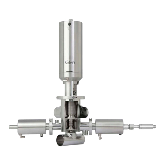
GEA Aseptomag DK Operating Instruction (106 pages)
Aseptic Valves, double chamber valve
Brand:
GEA
| Category:
Control Unit
| Size: 3 MB
Table of Contents
Legal Notice
2
Table of Contents
3
General Information
7
Information on the Document
7
Binding Character of These Operating Instructions
7
Notes on the Illustrations
7
Symbols and Highlighting
7
Manufacturer Address
8
Customer Service
8
EC Declaration of Incorporation
9
Safety
10
Intended Use
10
Dual-Chamber Valve
10
Loto Locking Mechanism
12
Integration of the Maintenance Fuse Loto
12
Requirements for Operation
16
Pressure Equipment Directive
16
ATEX Directive
16
Improper Operating Conditions
17
Operator's Duty of Care
17
Subsequent Changes
18
General Safety Instructions and Dangers
18
Principles for Safe Operation
18
Environmental Protection
19
Electrical Equipment
19
Supplementary Regulations
19
Qualification of Staff
19
Safety Equipment
21
Signs
21
Intervention Protection for Loto Locking Mechanism
21
Residual Dangers
22
Danger Zones
24
Description
25
Design of the Valve
25
Valve Identification
26
Sealing Concepts
29
Shrink-On Fit" Version
29
System "Divisible
29
Transport and Storage
31
Storage Conditions
31
Transport
31
Scope of Supply
31
Technical Data
32
Assembly and Installation
34
Safety Instructions
34
Notes on Installation
34
Welding in a Valve with Pipe Connection
34
Welding in and Installing a Valve
34
Welding Post-Treatment
35
Pneumatic Connections
36
Overview Switching Positions
36
Air Requirement
36
Establishing the Compressed Air Supply
37
Electrical Connections
37
Live Parts
37
Start-Up
39
Safety Instructions
39
Guideline for Lockout-Tagout Procedure
39
Notes on Commissioning
40
Operation and Control
41
Safety Instructions
41
Locking Mechanism Loto - Seat a
41
Unlock Seat a
41
Unlock Seat a - Restore Normal Operations
43
Air Lock Seat B
44
Lock the Seat B Air Connection
46
Unlock the Seat B Air Connection
47
Cleaning
48
Sterilisation
48
Passivation
48
Maintenance
50
Safety Instructions
50
Inspections
51
Bellows
51
Piston Rod Seal
51
Pneumatic Connections
51
Electrical Connections
51
Maintenance Intervals
52
List of Tools
52
Intended Purpose
58
Prior to Disassembly
59
Disassembling and Assembling the Valve
60
Removing the Valve
60
Installing the Valve
63
Torques for Clamp
63
Disassemble and Assemble the Side Valves
63
Overview Disassembly / Assembly Side Valve
63
Disassemble and Assemble Inside Part (Side Valve) - Versions "LVD" and "UV
64
Disassemble Piston Rod Seal (Side Valve) - Versions "LVD" and "UV
64
Assemble Piston Rod Seal (Side Valve) - Version "LVD" and "UV
65
Disassemble and Assemble Piston Rod Seal (Side Valve) - Version "LVD" and "UV
66
Disassemble Piston Rod Seal (Side Valve) - Version "LVD" and "UV
66
Assemble Piston Rod Seal (Side Valve) - Version "LVD" and "UV
67
Disassemble and Assemble Actuator PA50/PA60 (Side Valve)
68
Disassembling Actuator PA50/PA60 (Side Valve)
68
Installing Actuator PA50/PA60
73
Dismantle and Mount Piston Rod Seal (Side Valve) - Version "AV
73
Dismantle Piston Rod Seal (Side Valve) - Version "AV
73
Mount Piston Rod Seal (Side Valve) - Version "AV
74
Disassemble and Assemble the Internal Assembly "EA
75
Disassemble Internal Assembly "EA
75
Assemble Internal Assembly "EA
77
Torques for EA Valve Axes
79
Removing and Installing the "Shrunk-On" Valve Seat Seal
79
Removing the "Shrink-On Fit" Valve Seat Seal
79
Fitting the "Shrink-On Fit" Valve Seat Seal
80
Removing and Installing the "Divisible System" Valve Seat Seal (Seat A)
82
Disassemble the Valve Seat Seal "System Divisible" - Valve Version "EA
82
Assemble the Valve Seat Seal "System Divisible" - Valve Version "EA
84
Torques for Divisible Valve Discs
84
Carrying out the "Internal Assembly" Leak Test
84
Bubble Test
84
Disassembling and Assembling Actuator PA80EA - PA255EA
87
Disassembling the Actuator PA80EA - PA255EA
87
Mounting the Actuator PA80EA - PA255EA
91
Removing/Dismantling Loto Locking Mechanism
93
Dismantling Loto Locking Mechanism
93
Mounting the Loto Locking Mechanism
95
Maintenance
98
Checking the Feedback Unit
100
Setting the Feedback Unit
100
Valve Stroke
100
Alarms
101
Advertisement
GEA Aseptomag DK Operating Instruction (100 pages)
Aseptic double chamber valve
Brand:
GEA
| Category:
Control Unit
| Size: 3 MB
Table of Contents
Table of Contents
3
General Information
7
Binding Character of These Operating Instructions
7
Information on the Document
7
Notes on the Illustrations
7
Symbols and Highlighting
7
Customer Service
8
Manufacturer Address
8
EC Declaration of Incorporation
9
Safety
10
Intended Use
10
ATEX Directive
11
Pressure Equipment Directive
11
Requirements for Operation
11
Improper Operating Conditions
12
Operator's Duty of Care
12
General Safety Instructions and Dangers
13
Principles for Safe Operation
13
Subsequent Changes
13
Electrical Equipment
14
Environmental Protection
14
Qualification of Staff
14
Supplementary Regulations
14
Safety Equipment
16
Signs
16
Residual Dangers
17
Danger Zones
18
Description
19
Design of the Valve
19
Valve Identification
20
Sealing Concepts
23
Shrink-On Fit" Version
23
System "Divisible
23
Transport and Storage
25
Scope of Supply
25
Technical Data
26
Storage Conditions
25
Transport
25
Assembly and Installation
28
Notes on Installation
28
Safety Instructions
28
Welding in a Valve with Pipe Connection
28
Welding in and Installing a Valve
28
Welding Post-Treatment
29
Air Requirement
30
Overview Switching Positions
30
Pneumatic Connections
30
Electrical Connections
31
Start-Up
33
Establishing the Compressed Air Supply
31
Notes on Commissioning
33
Operation and Control
34
Safety Instructions
33
Safety Instructions
34
Cleaning
35
Passivation
35
Sterilisation
35
Maintenance
37
Safety Instructions
37
Bellows
38
Electrical Connections
38
Inspections
38
Piston Rod Seal
38
Pneumatic Connections
38
List of Tools
39
Maintenance Intervals
39
Disassembling and Assembling the Valve
46
Prior to Disassembly
46
Removing the Valve
46
Disassemble and Assemble the Side Valves
50
Installing the Valve
50
Overview Disassembly / Assembly Side Valve
50
Torques for Clamp
50
Disassemble and Assemble Inside Part (Side Valve) - Versions "LVD" and "UV
51
Disassemble Piston Rod Seal (Side Valve) - Versions "LVD" and "UV
51
Assemble Piston Rod Seal (Side Valve) - Version "LVD" and "UV
52
Disassemble and Assemble Piston Rod Seal (Side Valve) - Version "LVD" and "UV
53
Disassemble Piston Rod Seal (Side Valve) - Version "LVD" and "UV
53
Assemble Piston Rod Seal (Side Valve) - Version "LVD" and "UV
54
Disassemble and Assemble Actuator PA50/PA60 (Side Valve)
55
Disassembling Actuator PA50/PA60 (Side Valve)
55
Installing Actuator PA50/PA60
60
Dismantle and Mount Piston Rod Seal (Side Valve) - Version "AV
60
Dismantle Piston Rod Seal (Side Valve) - Version "AV
60
Mount Piston Rod Seal (Side Valve) - Version "AV
61
Disassemble and Assemble the Internal Assembly "EA
62
Disassemble Internal Assembly "EA
62
Assemble Internal Assembly "EA
65
Torques for EA Valve Axes
66
Disassemble and Assemble the Internal Assembly "AZ" and "NC
67
Disassemble Internal Assembly "AZ" and "NC
67
Disassemble and Assemble the Internal Assembly
68
Removing and Installing the "Shrunk-On" Valve Seat Seal
68
Removing the "Shrink-On Fit" Valve Seat Seal
68
Fitting the "Shrink-On Fit" Valve Seat Seal
69
Disassemble the Valve Seat Seal "System Divisible" - Valve Version "EA
71
Removing and Installing the "Divisible System" Valve Seat Seal
71
Assemble the Valve Seat Seal "System Divisible" - Valve Version "EA
73
Disassemble the Valve Seat Seal "System Divisible" - Valve Version "AZ" and "NC
73
Assemble the Valve Seat Seal "System Divisible" - Valve Version "AZ" and "NC
75
Bubble Test Valve Version "EA
75
Carrying out the "Internal Assembly" Leak Test (Bubble Test)
75
Torques for Divisible Valve Discs
75
Bubble Test Valve Versions "AZ" and "NC
78
Disassembling and Assembling Actuator PA80EA - PA255EA
80
Disassembling the Actuator PA80EA - PA255EA
80
Mounting the Actuator PA80EA - PA255EA
84
Disassembling Actuator PA80AZ - PA180AZ
86
Disassembling and Assembling Actuator PA80AZ - PA180AZ
86
Assembling Actuator PA80AZ - PA180AZ
88
Disassembling and Assembling Actuator PA80 - PA255
89
Removing Actuator PA80 - PA255
89
Assembling Actuator PA80 - PA255
91
Maintenance
91
Checking the Feedback Unit
93
Setting the Feedback Unit
93
Valve Stroke
93
Alarms
94
Malfunctions and Remedies
94
Decommissioning
96
Advertisement
Related Products
GEA Aseptomag AV
GEA Aseptomag RVIN
GEA Aseptomag AMV
GEA Aseptomag PV
GEA Aseptomag GD
GEA Aseptomag ADV
GEA Aseptomag LoTo
GEA ARIETE
GEA ATEX
GEA T.VIS A-15
GEA Categories
Control Unit
Air Compressor
Water Pump
Compressor
Industrial Equipment
More GEA Manuals
Login
Sign In
OR
Sign in with Facebook
Sign in with Google
Upload manual
Upload from disk
Upload from URL