
Related Manuals for GEA Aseptomag RVIN


Summary of Contents for GEA Aseptomag RVIN
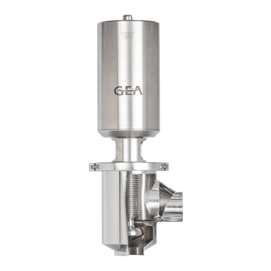
- Page 1 Aseptic Valves ® GEA Aseptomag Inverted Control Valve Type RVIN Operating instruction (Translation from the original language) 430BAL011926EN_1...
- Page 2 ® Aseptomag and TEFASEP are registered trademarks of GEA Aseptomag AG and may not be used without the permission of GEA Aseptomag AG. ® T.VIS is a protected trademark of GEA Tuchenhagen GmbH. We kindly request that you answer a few short questions about these Operating Instructions.
-
Page 3: Table Of Contents
TABLE OF CONTENTS General Information Information on the Document 1.1.1 Binding Character of These Operating Instructions 1.1.2 Notes on the Illustrations 1.1.3 Symbols and Highlighting Manufacturer address Customer service EC Declaration of Incorporation Safety Intended use 2.1.1 Requirements for operation 2.1.2 Pressure equipment directive 2.1.3... - Page 4 10.1 Safety instructions 10.2 Inspections 10.2.1 Bellows 10.2.2 Pneumatic connections 10.2.3 Electrical connections 10.3 Maintenance intervals 10.4 List of tools 10.5 Prior to disassembly 10.6 Disassembling and assembling the positioner 10.6.1 Available positioners 10.7 Disassembling and Assembling the Valve 10.7.1 Dismantling the Valve into its Main Components 10.7.2 Installing the valve...
-
Page 5: General Information
General Information Information on the Document General Information Information on the Document The present Operating Instructions are part of the user information for the product. The Operating Instructions contain all the information you need to transport, install, commission, operate and carry out maintenance for the product. 1.1.1 Binding Character of These Operating Instructions These Operating Instructions contain the manufacturer's instructions to the... -
Page 6: Manufacturer Address
Result of the previous operation. ® The operation is complete, the goal has been achieved. Hint! Further useful information. Manufacturer address GEA Aseptomag AG Industrie Neuhof 28 CH-3422 Kirchberg Customer service Phone: +41 (0)34 426 29 29 Fax: +41 (0)34 426 29 28 service.aseptomag@gea.com... -
Page 7: Ec Declaration Of Incorporation
Teamleader Product Development Flow Components – Aseptic Valves GEA Aseptomag AG GEA Aseptomag AG Tel. +41 34 426 29 29 · Fax +41 34 426 29 28 · gea.com Industrie Neuhof 28, CH-3422 Kirchberg Seite 1 von 1 430BAL011926EN_1 30.08.2019... -
Page 8: Safety
The valve is a piece of pressure equipment (without safety function) as defined in the Pressure Equipment Directive: Directive 2014/68/EG. It is classified according to Annex II, article 4, section 3. In the event of any deviations, GEA Aseptomag AG will supply a specific Declaration of Conformity. -
Page 9: Operator's Duty Of Care
Safety Operator’s Duty of Care The operation of the component is not permitted if: • Persons or objects are in the danger zone. • Safety devices are not working or were removed. • Malfunctions have been detected on the component. •... -
Page 10: Subsequent Changes
EC Machinery Directive on your own. In general, only original spare parts supplied by GEA Aseptomag AG should be fitted. This ensures the reliable and economical operation of the valve. -
Page 11: Electrical Equipment
Safety Supplementary Regulations • Substances harmful to the environment must be collected and stored in suitable containers. Clearly mark the containers. • Dispose of lubricants as hazardous waste. 2.4.3 Electrical Equipment For all work on electrical equipment, the following principles apply: •... -
Page 12: Safety Equipment
Safety Safety equipment • Personal suitability for the respective task. • Sufficient professional qualification for the respective task. • Received instruction about the functionality of the component. • Received instruction about operating sequences on the component. • Familiar with the safety devices and their function. •... -
Page 13: Residual Dangers
Safety Residual dangers Residual dangers Dangerous situations can be avoided by safety-conscious and proactive behaviour of the personnel and by wearing personal protective equipment. Residual dangers on the valve and measures Danger Cause Measure Danger to life Inadvertent Effectively disconnect all components, effectively prevent switch-on of the switch-on. - Page 14 Safety Fig.1: Danger zone at the valve • In the event of malfunctions, shut down the valve (disconnect from the power and air supply) and secure it against being used. • Never reach into the lantern (1) or the valve housing (2) when the valve is switching.
-
Page 15: Description
Description Design of the valve Description Design of the valve Fig.2: Main components on the valve Designation Housing Internal assembly Clamp (safety device) Actuator Additional components key Designation Mounting kit Positioner Hint! A positioner with a corresponding mounting kit converts the valve into the functioning regulating unit. -
Page 16: Valve Identification
Description Valve Identification Valve Identification Reference numbers from the following number systems are assigned to each part of components from GEA Aseptomag AG. The reference numbers can be used to clearly identify a component and its composition. Number Designation Description... - Page 17 Description Valve Identification Example Position Details V-50-1233 Valve Drawing number of valve housing housing 1.4435 AB 333937 Material and re-stamping details 0212 16 Valve Serial number of valve housing housing V-50-1004 Clamp Number of clamp drawing V-50-2200 Internal Drawing number of internal assembly assembly 1325 16 Serial number of internal assembly...
-
Page 18: Inverted Valve Function
Description Inverted Valve Function Inverted Valve Function Fig.4: Function NC: Actuator type normally closed NO: Valve type normally open For an inverted single-seat valve it should be noted that, compared with a standard single-seat valve, the direction of action of an actuator will produce exactly the reverse effect when the same amount of force is applied. -
Page 19: Sealing Concepts
Sealing Concepts “OVSD” system, which means • Undivided valve disc • Without valve seat seal • GEA Aseptomag standard for inverted control valves • Metallic seal, not leakage-free! Fig.5: “OVSD” system Control loop of the positioner (example) • Valve with mounting kit and positioner •... - Page 20 Description Fig.6: Control loop positioner Setpoint value Command (mA) Actual value Flow direction product 430BAL011926EN_1 30.08.2019...
-
Page 21: Transport And Storage
Transport and storage Storage conditions Transport and storage Storage conditions The valves, valve inserts or spare parts should be stored in a dry place, free of vibrations and dust, and protected from light. To avoid damage, leave the components in their original packaging if possible. If, during transport or storage, the valve is going to be exposed to temperatures ≤... -
Page 22: Technical Data
Technical data Technical data Technical data Technical data Operating data (for valve with sealing material silicone) Max. operating temperature 150 °C (302 °F) Max. sterilisation temperature 160 °C (320 °F) for max. 30 min. Max. product pressure 5 … 6 bar (others on request) Control air pressure, actuator 6 bar, maximum 8 bar Nominal pressure... -
Page 23: Control Parameters
Technical data Control parameters Compressed air supply Compressed air supply 6 bar, compressed air filtered (at least 0,5 µm), oil-free. Cleaning Cleaning The valve is suitable for CIP cleaning (Cleaning in Place) Recommended cleaning speed At least 2 m/s in the valve Sterilisation Sterilisation The valve is suitable for SIP sterilisation (Sterilisation in Place) -
Page 24: Assembly And Installation
Assembly and installation Safety instructions Assembly and installation Safety instructions Hazardous situations during installation can be avoided by safety-conscious and proactive behaviour of the personnel. For installation, the following principles apply: • Only qualified personnel are allowed to set-up, install and commission the component. -
Page 25: Welding Post-Treatment
Assembly and installation Welding In a Valve with Pipe Connection Caution! Danger of injury due to spring force being released You can sustain injuries to your fingers when you put your hand into a valve if the valve has not been moved to the open position beforehand. ►... -
Page 26: Pneumatic Connections
Assembly and installation Pneumatic connections • polishing. Pneumatic connections 6.4.1 Air requirement The air requirement depends on the type of actuator fitted. The following tables show guideline values at an air pressure supply of 6 bar per valve size and the corresponding actuator size used as a standard. - Page 27 Assembly and installation Danger Live parts Electrical shock can result in serious personal injury or death. ► Only allow properly qualified staff to carry out work on the electrical equipment. ► Prior to establishing electrical connections check the maximum permissible operating voltage. Explosive gases or dusts An explosion can result in serious personal injury or death.
-
Page 28: Start-Up
Start-up Safety instructions Start-up Safety instructions Initial commissioning For initial commissioning, the following principles apply: • Take protective measures against dangerous contact voltages in accordance with pertinent regulations. • The valve must be completely assembled and correctly adjusted. All screw connections must be securely tightened. -
Page 29: Operation And Control
Operation and control Safety instructions Operation and control Safety instructions Dangerous situations during operation can be avoided by safety-conscious and proactive behaviour of the personnel. For operation, the following principles apply: • Monitor the component during operation. • Safety devices must not be changed, removed or taken out of service. Check all safety devices at regular intervals. -
Page 30: Cleaning
Cleaning Cleaning Cleaning Cleaning The valve is suitable for CIP (Cleaning in Place); recommended cleaning speed in the valve is at least 2 m/s. All parts in contact with product must be cleaned at regular intervals. Always observe the safety data sheets issued by the cleaning agent manufacturers. Only use cleaning agents which do not cause damage to the seals and the inner parts of the valve. -
Page 31: Maintenance
Maintenance Safety instructions Maintenance 10.1 Safety instructions Maintenance and repair Before carrying out maintenance and repair work on the component's electrical equipment, perform the following steps in accordance with the "5 safety rules": • Isolate from the power supply • Take appropriate measures to prevent switch on •... -
Page 32: Inspections
Maintenance Inspections • Disconnect all power and utility lines. • Markings, e.g. on lines, must not be removed. • Do not climb on the component. Use suitable access aids and working platforms. • Mark the lines (if unmarked) prior to disassembly to ensure they are not confused when re-assembling. -
Page 33: List Of Tools
If information regarding the definition of practical-oriented maintenance intervals is not available or is insufficient, the guideline values listed in the "Maintenance" chapter can be referred. This information is based on empirical values for GEA Flow Components and relates to installations working in two-shift operation. - Page 34 Maintenance List of tools List of tools (in alphabetical order) Material Number Tool Figure Intended Purpose GEA Aseptomag AG Valves Hex socket key 0980.50121 DN 15 - DN 80 S-12-0554 Tighten/release clamp Fig.10 Mounting tool PA80-210 0981.50008 Spring package Remove/insert spring...
-
Page 35: Prior To Disassembly
For each of the listed positioners there is a specially designed mounting kit, whose disassembly / assembly is explained in a separate manual. These additional documents are provided upon request by GEA Aseptomag, see Section 10.6.1, Page 36. 430BAL011926EN_1... -
Page 36: Available Positioners
Disassembling and Assembling the Valve 10.6.1 Available positioners Positioner with available actuators and mounting kits Material number of the mounting kit Positioner Actuator size GEA Aseptomag AG T.VIS P-15 PA60 – PA210 0984.00038 Siemens PS2 PA60 – PA210 0963.10000 Samson 3730-1, 3730-2, PA60 –... - Page 37 Maintenance Disassembling and Assembling the Valve Fig.17: Apply valve NO Release the clamp with a suitable hex socket key, but do not unhook the screw yet. Fig.18: Loosening the clamp screw ! Make sure that the clamp can be moved by hand and without a great deal of force before you carry out the next step.
-
Page 38: Installing The Valve
Maintenance Disassembling and Assembling the Internal Assembly Fig.19: Removing actuator and internal assembly ® Internal assembly and actuator are now separated from the housing. 10.7.2 Installing the valve Tools required: • Hex socket key Carry out the following steps: Install the valve in the reverse order of disassembly, see Section 10.7.1, Page 36. - Page 39 Maintenance Disassembling and Assembling the Internal Assembly Caution! Danger of injury due to valve parts moved by compressed air! You can sustain injuries to your fingers when you put your hand into the valve while it is switching. ► Wear protective gloves for all work. ►...
-
Page 40: Installing The Internal Assembly
Maintenance Carrying out the "Internal assembly" leak test (bubble test) ® The internal assembly has been removed. 10.8.2 Installing the internal assembly Hint! Pay attention to the following points when assembling the internal assembly: • Thoroughly clean all parts and check for damage. •... - Page 41 Maintenance Carrying out the "Internal assembly" leak test (bubble test) Fig.23: Hook in the internal assembly Place the clamping arms of the pressurizing tools around the valve cover. Fig.24: Attach clamping arms Pull the valve cover against the seal by means of the star grip on the pressurizing tool (hand-tight).
-
Page 42: Disassembling And Assembling Actuator Pa80 - Pa255
Maintenance Disassembling and Assembling Actuator PA80 - PA255 Fig.26: Connecting compressed air Immerse the internal assembly in a water bath for approx. 30 seconds. ! During immersion, check the internal assembly for leakage. Leakages will become visible through rising bubbles. Fig.27: Water bath Remove the internal assembly from the pressurizing tool in reverse order. - Page 43 Maintenance Disassembling and Assembling Actuator PA80 - PA255 Bring the actuator to the non-actuated position. Remove the feedback unit. Attach the clamping piece on the rear of the actuator. Fig.28: Attaching clamping piece Clamp the actuator at the clamping piece into the vice . Fig.29: Clamping the actuator ®...
- Page 44 Maintenance Disassembling and Assembling Actuator PA80 - PA255 Fig.30: Releasing assembly spring Turn the actuator base clockwise using the flexible head spanner . ! Rotate the actuator base until the assembly spring can be removed. Fig.31: Unscrewing assembly spring ® Assembly spring has been removed.
-
Page 45: 10.10.2 Assembling Actuator Pa80 - Pa255
Maintenance Disassembling and Assembling Actuator PA80 - PA255 Fig.33: Lifting out spring package ® Actuator has been dismantled into its individual parts. ! Opening the spring assembly is forbidden for safety reasons. ® Actuator PA80 - PA255 has been disassembled. 10.10.2 Assembling Actuator PA80 - PA255 Hint! Pay attention to the following points when assembling the actuator:... - Page 46 Maintenance Disassembling and Assembling Actuator PA80 - PA255 • Slotted screwdriver Carry out the following steps: Align the actuator base relative to the cylinder housing so that the hole in the base is visible through the slot in the cylinder. Fig.34: Aligning hole to slot Insert the angled part of the assembly spring into the hole of the actuator...
-
Page 47: Maintenance
Prior to any work on the open valve, ensure that it has stopped operation, see Section 10.5, Page 35. The following information and values are based on the experience of GEA Flow Components and apply for installations working in 2-shift operation. - Page 48 Maintenance Maintenance Activities to be performed once a month Component Activity to be performed Valve Visual inspection Activities to be performed after 3 months (only after initial commissioning or after a process change) Component Activity to be performed Check of mechanical parts and visual inspection of Product contact seals condition Check of mechanical parts and visual inspection of...
-
Page 49: Check And Adjust The Positioner
Maintenance Check and adjust the positioner Activities to be performed every 5 years Component Activity to be performed Actuator Maintenance including seal replacement 10.12 Check and adjust the positioner After maintenance, the positioner must be properly reassembled. The function must also be checked and, if necessary, reset. During assembly and readjustment, the information provided in the corresponding manual must be followed. -
Page 50: Alarms
Alarms Malfunctions and remedies Alarms 11.1 Malfunctions and remedies Notice Warning of damage to property/loss of product Ignoring malfunctions may cause considerable damage to property and loss of product. The safe operation of the valve in the event of a malfunction can no longer be taken for granted and in the worst case can result in a loss of sterility in the process. - Page 51 Alarms Malfunction Cause Remedy The maximum valve stroke is Check the seals in the actuator not reached when the valve is Leakage in the actuator. for damage. Replace the seals. actuated pneumatically. • Check positioner for correct • The positioner is not installation.
-
Page 52: Decommissioning
Decommissioning Safety instructions Decommissioning 12.1 Safety instructions For shutting down, the following principles apply: • Switch off the compressed air. • Switch off the component with the main switch. • Padlock the main switch (if fitted) in the off position to prevent it from being switched back on. -
Page 53: Appendix
Appendix Lists Appendix 13.1 Lists 13.1.1 Abbreviations and terms Abbreviation Explanation ° Symbol for the grade of a scale [degrees] All degree data is assumed to be angle degrees unless explicitly specified otherwise. °C Unit of measurement of temperature [degree Celsius] °F Unit of measurement of temperature [degree Fahrenheit] AISI... - Page 54 Appendix Abbreviation Explanation Normally Closed; direction of action spring-closing/air-opening Unit of measurement of work [newton metre] Unit of torque 1 Nm = 0.737 lbft Pound-Force (lb) + Feet (ft) Normally Open; direction of action air-closing/spring-opening Outside diameter; short name for outside diameter for inch tubes according to DIN 11866-C Pneumatic actuator PTFE...
- Page 55 Appendix 430BAL011926EN_1 30.08.2019...
Need help?
Do you have a question about the Aseptomag RVIN and is the answer not in the manual?
Questions and answers