
Related Manuals for GEA Aseptomag ADV


Summary of Contents for GEA Aseptomag ADV
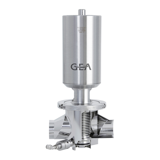
- Page 1 Aseptic Valves ® leakage valve type ADV GEA Aseptomag Operating instruction (Translation from the original language) 430BAL012841EN_1...
- Page 2 ® Aseptomag and TEFASEP are registered trademarks of GEA Aseptomag AG and may not be used without the permission of GEA Aseptomag AG. ® T.VIS is a protected trademark of GEA Tuchenhagen GmbH. We kindly request that you answer a few short questions about these Operating Instructions.
-
Page 3: Table Of Contents
TABLE OF CONTENTS General Information Information on the Document 1.1.1 Binding Character of These Operating Instructions 1.1.2 Notes on the Illustrations 1.1.3 Symbols and Highlighting Manufacturer address Customer service EC Declaration of Incorporation Safety Intended use 2.1.1 Requirements for operation 2.1.2 Pressure equipment directive 2.1.3... - Page 4 10.2 Inspections 10.2.1 Bellows 10.2.2 Pneumatic connections 10.2.3 Electrical connections 10.3 Maintenance intervals 10.4 List of tools 10.5 Prior to disassembly 10.6 Disassembling and Assembling the Valve 10.6.1 Disassembling the Valve 10.6.2 Assembling the Valve 10.6.3 Torques for clamp 10.7 Disassemble and assemble actuator PA20 (side valve) 10.7.1 Disassemble actuator PA20 (side valve)
-
Page 5: General Information
General Information Information on the Document General Information Information on the Document The present Operating Instructions are part of the user information for the product. The Operating Instructions contain all the information you need to transport, install, commission, operate and carry out maintenance for the product. 1.1.1 Binding Character of These Operating Instructions These Operating Instructions contain the manufacturer's instructions to the... -
Page 6: Manufacturer Address
Result of the previous operation. ® The operation is complete, the goal has been achieved. Hint! Further useful information. Manufacturer address GEA Aseptomag AG Industrie Neuhof 28 CH-3422 Kirchberg Customer service Phone: +41 (0)34 426 29 29 Fax: +41 (0)34 426 29 28 service.aseptomag@gea.com... -
Page 7: Ec Declaration Of Incorporation
Teamleader Product Development Flow Components – Aseptic Valves GEA Aseptomag AG GEA Aseptomag AG Tel. +41 34 426 29 29 · Fax +41 34 426 29 28 · gea.com Industrie Neuhof 28, CH-3422 Kirchberg Seite 1 von 1 430BAL012841EN_1 07.03.2018... -
Page 8: Safety
Safety Intended use Safety Intended use Aseptic leakage valves are mix-proof switch elements for aseptic process systems and permit the safe separation of incompatible media. The media separation is done via the integrated sterile chamber (ISB), which is separated hermetically from the atmosphere with a seal each to both product lines and via two side valves (inlet and outlet). -
Page 9: Requirements For Operation
The valve is a piece of pressure equipment (without safety function) as defined in the Pressure Equipment Directive: Directive 2014/68/EG. It is classified according to Annex II, article 4, section 3. In the event of any deviations, GEA Aseptomag AG will supply a specific Declaration of Conformity. -
Page 10: Improper Operating Conditions
Safety Operator’s Duty of Care ® Aseptomag valve technology can also be used in ATEX protected areas. However, the suitability of the component must be checked under consideration of the respective conditions. Additional information will be made available upon request. 2.1.4 Improper operating conditions The operational reliability of the valve cannot be ensured under improper... -
Page 11: Subsequent Changes
EC Machinery Directive on your own. In general, only original spare parts supplied by GEA Aseptomag AG should be fitted. This ensures the reliable and economical operation of the valve. -
Page 12: Environmental Protection
Safety Supplementary Regulations 2.4.2 Environmental Protection Harm to the environment can be avoided by safety-conscious and proactive behaviour of the staff. For environmental protection the following principles apply: • Substances harmful to the environment must not be discharged into the ground or the sewage system. - Page 13 Safety Qualification of personnel Only allow specially trained personnel to carry out work on an explosion- protected system. When working on explosion-protected equipment observe the standards DIN EN 60079-14 for gases and DIN EN 50281-1-2 for dusts. The following minimum qualifications are required: •...
-
Page 14: Safety Equipment
Safety Safety equipment User groups Staff Qualifications Operating personnel Adequate instruction and sound knowledge in the following areas: • Functionality of the component • Operating sequences on the pump • What to do in case of an emergency • Lines of authority and responsibilities with respect to the task Maintenance personnel Appropriate training and a sound knowledge of the structure and functionality of the component. -
Page 15: Danger Zones
Safety Danger zones Residual dangers on the valve and measures Danger Cause Measure Danger to life Inadvertent Effectively disconnect all components, effectively prevent switch-on of the switch-on. valve Electric power Observe the following safety rules: Isolate from the power supply. Take appropriate measures to prevent switch on. - Page 16 Safety Fig.4: Danger zone at the valve • In the event of malfunctions, shut down the valve (disconnect from the power and air supply) and secure it against being used. • Never reach into the motor stool (1) or the valve housing (2) when the valve is switching.
-
Page 17: Description
Description Design of the Valve Description Design of the Valve Fig.5: Main components on the valve Designation Housing Internal assembly Valve seat A Valve seat B Actuator Clamp (safety device) Inlet valve (side valve) Connecting pieces for the inlet valve Outlet valve (side valve) Connecting pieces for the outlet valve 430BAL012841EN_1... -
Page 18: Valve Identification
Description Valve Identification Valve Identification Reference numbers from the following number systems are assigned to each part of components from GEA Aseptomag AG. The reference numbers can be used to clearly identify a component and its composition. Number Designation Description... - Page 19 Description Valve Identification Fig.6: Designations on the valve Example Position Details V-50-1002 Valve Drawing number of valve housing housing 1.4435 TC 333937 Material and re-stamping details 0548 10 Valve Serial number of valve housing housing V-50-2200 Internal Drawing number of internal assembly assembly 1424 10 Serial number of internal assembly...
-
Page 20: Sealing Concepts
Description Sealing Concepts Sealing Concepts 3.3.1 System "separable" Valve seat seals GEA Aseptomag standard TVET Divisible valve discs, EPDM radial seal (seat A) / TEFASEP seal (seat B) GEA Aseptomag option TVEP Divisible valve discs, EPDM radial seal (seat A) /... -
Page 21: Transport And Storage
Transport and storage Storage conditions Transport and storage Storage conditions The valves, valve inserts or spare parts should be stored in a dry place, free of vibrations and dust, and protected from light. To avoid damage, leave the components in their original packaging if possible. If, during transport or storage, the valve is going to be exposed to temperatures ≤... -
Page 22: Technical Data
Technical data Technical data Technical data Technical data Operating data (for valve with sealing materials Tefasep and EPDM) Max. operating temperature 135 °C (275 °F) Max. sterilisation temperature 150 °C (302 °F) for max. 30 min. Max. product pressure 5 ... 6 bar (others on request) Control air pressure, actuator 6 bar, max. - Page 23 Technical data Compressed air supply Compressed air supply 6 bar, compressed air filtered (at least 0,5 µm), oil-free. Cleaning Cleaning The valve is suitable for CIP cleaning (Cleaning in Place) Recommended cleaning speed At least 2 m/s in the valve Sterilisation Sterilisation The valve is suitable for SIP sterilisation (Sterilisation in Place)
-
Page 24: Assembly And Installation
Assembly and installation Safety instructions Assembly and installation Safety instructions Hazardous situations during installation can be avoided by safety-conscious and proactive behaviour of the personnel. For installation, the following principles apply: • Only qualified personnel are allowed to set-up, install and commission the component. -
Page 25: Welding Post-Treatment
Assembly and installation Welding In a Valve with Pipe Connection Caution! Danger of injury due to spring force being released You can sustain injuries to your fingers when you put your hand into a valve if the valve has not been moved to the open position beforehand. ►... -
Page 26: Pneumatic Connections
Assembly and installation Pneumatic connections • polishing. Pneumatic connections 6.4.1 Overview switching positions Fig.9: Air connections valve type AZ (labelled on the actuator) Function Valve seat Air connection Open “A“ + “B“ "D" Venting (AZ) “B“ "C" Control Side valve ®... -
Page 27: Establishing The Compressed Air Supply
Assembly and installation Electrical connections Air requirements for actuator of the side valve Nominal width Actuator Air requirements [dm DN 15 PA20 0.02 6.4.3 Establishing the Compressed Air Supply A prerequisite for the reliable operation of the valve is that the compressed air hoses are cut exactly square. -
Page 28: Start-Up
Start-up Safety instructions Start-up Safety instructions Initial commissioning For initial commissioning, the following principles apply: • Take protective measures against dangerous contact voltages in accordance with pertinent regulations. • The valve must be completely assembled and correctly adjusted. All screw connections must be securely tightened. -
Page 29: Operation And Control
Operation and control Safety instructions Operation and control Safety instructions Dangerous situations during operation can be avoided by safety-conscious and proactive behaviour of the personnel. For operation, the following principles apply: • Monitor the component during operation. • Safety devices must not be changed, removed or taken out of service. Check all safety devices at regular intervals. -
Page 30: Cleaning
Cleaning Cleaning Cleaning Cleaning The valve is suitable for CIP (Cleaning in Place); recommended cleaning speed in the valve is at least 2 m/s. All parts in contact with product must be cleaned at regular intervals. Always observe the safety data sheets issued by the cleaning agent manufacturers. Only use cleaning agents which do not cause damage to the seals and the inner parts of the valve. - Page 31 Cleaning Passivation is typically performed using nitric acid (HNO ) at approx. 80 °C (176 °F) at a concentration of 3 % and a contact time of 6 to 8 hours. The ultimate temperatures, chemicals, concentrations and contact time to be used must be determined by the plant operator along with its chemical supplier.
-
Page 32: Maintenance
Maintenance Safety instructions Maintenance 10.1 Safety instructions Maintenance and repair Before carrying out maintenance and repair work on the component's electrical equipment, perform the following steps in accordance with the "5 safety rules": • Isolate from the power supply • Take appropriate measures to prevent switch on •... - Page 33 Maintenance Inspections • Disconnect all power and utility lines. • Markings, e.g. on lines, must not be removed. • Do not climb on the component. Use suitable access aids and working platforms. • Mark the lines (if unmarked) prior to disassembly to ensure they are not confused when re-assembling.
- Page 34 Section 10.5, Page 38. 10.4 List of tools List of tools (in alphabetical order) Material Number Tools Figure Intended Purpose GEA Aseptomag AG Valves Pressurizing tool 0980.50003 DN 10 - DN 80 DN 10 - DN 80 S-12-0010 Inspection of metal bellows Fig.10...
- Page 35 Maintenance List of tools List of tools (in alphabetical order) Material Number Tools Figure Intended Purpose GEA Aseptomag AG Pressure control valve Inspection of metal 9999.10090 bellows Ø 6 mm Fig.13 Flexible head spanner PA80-135 0980.10009 Ø60-90mm, Remove/fit assembly S-12-0332 spring Pin Ø...
- Page 36 Maintenance List of tools List of tools (in alphabetical order) Material Number Tools Figure Intended Purpose GEA Aseptomag AG Assembly tool PA20-210 0981.50008 Spring assembly Remove/insert spring S-12-0209 PA20-210 assembly Fig.19 Assembly tool PA20-210 5050.51064 Clamping piece Hold cylinder S-12-0005 PA20-210 Fig.20...
- Page 37 Maintenance List of tools List of tools (in alphabetical order) Material Number Tools Figure Intended Purpose GEA Aseptomag AG DN 40 TV Spanner adapter 5050.51604 Loosen / tighten SW13 S-12-0140 divisible valve disks Fig.24 DN 50 - 65 TV Spanner adapter 5050.51605...
- Page 38 Maintenance Prior to disassembly List of tools (in alphabetical order) Material Number Tools Figure Intended Purpose GEA Aseptomag AG Seeger circlip pliers PA20 - 60 0980.50108 Inside diameter 40-100 Remove/fit PA S-12-0541 angled tip, 90° Fig.29 Inspection of metal Shut-off valve Ø 6 mm 9999.10091...
- Page 39 Maintenance Disassembling and Assembling the Valve Caution! Danger of injury due to spring force being released You can sustain injuries to your fingers when you put your hand into a valve if the valve has not been moved to the open position beforehand. ►...
- Page 40 Maintenance Disassembling and Assembling the Valve Fig.33: Disconnect the pipe connection Secure the side valve actuator against falling down, loosen it with a suitable open-end wrench and carefully remove it. Fig.34: Remove side valve Release the clamp of the main valve with a suitable hex socket key, but do not unhook the screw yet.
- Page 41 Maintenance Disassembling and Assembling the Valve Carefully take off the clamp from the valve. Carefully lift the actuator with the internal assembly out of the housing. ! Do not damage the sealing surface on the valve body. Fig.36: Removing actuator and internal assembly ®...
- Page 42 Maintenance Disassemble and assemble actuator PA20 (side valve) 10.6.3 Torques for clamp Clamp screw thread size Recommended torque [Nm] 10.7 Disassemble and assemble actuator PA20 (side valve) 10.7.1 Disassemble actuator PA20 (side valve) Tools required: • Seeger circlip pliers • Open end spanner Caution! Danger of injury due to spring force being released...
- Page 43 Maintenance Disassemble and assemble actuator PA20 (side valve) ! Release the spring pressure by pushing the valve seat downwards by hand. After removing the ring, slowly relieve the spring. Fig.38: Removing the circlip Carefully lift the actuator components out of the drive cylinder. Remove the housing seal (1) without a tool.
- Page 44 Maintenance Disassembling and Assembling the Internal Assembly Hint! Pay attention to the following points when assembling the actuator: • Replace all visible seals. • Thoroughly clean and check the interior cylinder contact surfaces, O-ring grooves and piston. • When changing the seals, do not damage the seal groove. •...
- Page 45 Maintenance Disassembling and Assembling the Internal Assembly Fig.40: Extend the piston rod with the groove upwards. Lift the internal assembly slightly to detach it from the T-slot on the drive spindle. Fig.41: Unhooking the internal assembly Remove the housing seal without a tool. ! Do not damage the sealing surfaces on the housing and internal assembly.
- Page 46 Maintenance Removing and Installing the "Divisible System" Valve Seat Seal Hint! Seals in the product-contacting area are generally not lubricated. To facilitate assembly (better gliding properties and securing against turning), this type of elastomer seal may, however, be wetted using a food-grade lubricant.
- Page 47 TVET & TVEP Fig.45: Remove seal TVET GEA Aseptomag standard Divisible valve disc, EPDM radial seal (Seat A) / TEFASEP seal (Seat B) TVEP GEA Aseptomag option Divisible valve disc, EPDM radial seal (Seat A) / PTFE seal (Seal B)
- Page 48 Maintenance Removing and Installing the "Divisible System" Valve Seat Seal Hint! Seals in the product-contacting area are generally not lubricated. To facilitate assembly (better gliding properties and securing against turning), this type of elastomer seal may, however, be wetted using a food-grade lubricant.
- Page 49 Maintenance Removing and Installing the "Divisible System" Valve Seat Seal Fig.47: Fitting elastomer seals Heat new thermoplastic valve seat seal for seat B in the oven. – Temperature: 140 °C (guideline value) – Time: 3 - 5 minutes (guideline value) ! Make sure that the seal can be deformed along the circumference without much effort.
- Page 50 Maintenance Carrying out the “Internal Assembly” Leak Test (Bubble Test) Fig.49: Tight the nut for the valve disc ! After fitting a new TEFASEP valve seat seal, the valve may not be tight. The valve seat seal will adjust itself optimally to the sealing surfaces only after the first sterilisation of the valve (see Chapter 9, Page 30).
- Page 51 Maintenance Carrying out the “Internal Assembly” Leak Test (Bubble Test) • Pressure regulating valve Ø 6 mm • Water bath Carry out the following steps: Insert the internal assembly with the T-slot of the valve spindle of the removed internal assembly into the pressurizing tool. Fig.50: Hook in the internal assembly Place the clamping arms of the pressurizing tool around the valve cap.
- Page 52 Maintenance Disassembling and Assembling Actuator PA80 - PA255 Fig.52: Secure internal assembly Apply max. 3 bar of compressed air to the pressurizing tool. ! Air pressures > 3 bar can damage the metal bellows. Immerse the internal assembly in a water bath for approx. 30 seconds. ! While the internal assembly is immersed, check the internal assembly for leaks.
- Page 53 Maintenance Disassembling and Assembling Actuator PA80 - PA255 • Vice Preparing disassembly Carry out the following steps: Bring the actuator to the non-actuated position. Remove the feedback unit. Fasten assembly tool "clamping piece" on the rear of the actuator. Fig.54: Attaching clamping piece Grip the actuator in the vice using the clamping piece.
- Page 54 Maintenance Disassembling and Assembling Actuator PA80 - PA255 Fig.56: Releasing assembly spring Turn the actuator base clockwise using the flexible head spanner. ! Rotate the actuator base until the assembly spring can be removed. Fig.57: Unscrewing assembly spring ® Assembly spring has been removed. PA80 - PA255: dismantling the actuator Carry out the following steps: Lift off the actuator base from the cylinder.
- Page 55 Maintenance Disassembling and Assembling Actuator PA80 - PA255 Fig.59: Lifting out spring assembly ® Actuator has been dismantled into its individual parts. ! Opening the spring assembly is not recommended for safety reasons. ® Actuator PA80 - PA255 has been disassembled. 10.11.2 Assembling Actuator PA80 - PA255 Hint! Pay attention to the following points when assembling the actuator:...
- Page 56 Maintenance Disassembling and Assembling Actuator PA80 - PA255 • Slotted screwdriver Carry out the following steps: Align the actuator base relative to the cylinder housing so that the hole in the base is visible through the slot in the cylinder. Fig.60: Aligning hole to slot Insert the angled part of the assembly spring into the hole of the actuator...
- Page 57 Maintenance Disassembling and Assembling Actuator PA80AZ - PA180AZ Fig.63: Fastening the assembly spring ® The assembly spring moves out of the hole when it reaches the slot in the cylinder and actuator base was turned further? – Continue to turn the actuator base counter-clockwise using the flexible head spanner until the hole is again located underneath the position pin of the assembly spring and the pin can be pressed in again with the slotted screwdriver.
- Page 58 Maintenance Disassembling and Assembling Actuator PA80AZ - PA180AZ Removing assembly spring Carry out the following steps: Disassemble assembly spring, see Page 53. ® Assembly spring has been removed. PA80AZ - PA180AZ: dismantling the actuator Carry out the following steps: Lift off the actuator base from the cylinder. Fig.65: Removing actuator base Use the assembly tool for the spring assembly to pull the spring assembly...
- Page 59 Maintenance Disassembling and Assembling Actuator PA80AZ - PA180AZ Fig.67: Removing circlip Take the buffer segments out of the actuator base. Fig.68: Removing securing elements Lift the piston disc out of the actuator base. Fig.69: Lifting out the piston disc ® Actuator has been dismantled into its individual parts.
- Page 60 Prior to any work on the open valve, ensure that it has stopped operation, see Section 10.5, Page 38. The following information and values are based on the experience of GEA Aseptomag AG and apply for installations working in 2-shift operation.
- Page 61 Maintenance Maintenance Activities to be performed after 3 months (only after initial commissioning or after a process change) Component Activity to be performed Check of mechanical parts and visual inspection of Product contact seals condition Check of mechanical parts and visual inspection of Internal assembly with condition bellows...
- Page 62 Maintenance Checking the Feedback Unit 10.14 Checking the Feedback Unit After completing maintenance work, check the function of the feedback unit and readjust it if necessary. 10.14.1 Setting the Feedback Unit Carry out the following steps: Set the initiator for detection of the rest position. Actuate the valve with compressed air.
- Page 63 Alarms Malfunctions and remedies Alarms 11.1 Malfunctions and remedies Notice! Warning of damage to property/loss of product Ignoring malfunctions may cause considerable damage to property and loss of product. The safe operation of the valve in the event of a fault can no longer be taken for granted and in the worst case can result in a loss of sterility in the process.
- Page 64 Alarms Malfunction Cause Remedy • Check the sealing surfaces The maximum valve stroke is in the actuator for damage. not reached when the valve is Leakage in the actuator. actuated pneumatically. • Replace the seals. • Check that the feedback •...
- Page 65 Decommissioning Safety instructions Decommissioning 12.1 Safety instructions For shutting down, the following principles apply: • Switch off the compressed air. • Switch off the component with the main switch. • Padlock the main switch (if fitted) in the off position to prevent it from being switched back on.
- Page 66 Appendix Lists Appendix 13.1 Lists 13.1.1 Abbreviations and terms Abbreviation Explanation ° Symbol for the grade of a scale [degrees] All degree data is assumed to be angle degrees unless explicitly specified otherwise. °C Unit of measurement of temperature [degree Celsius] °F Unit of measurement of temperature [degree Fahrenheit] AISI...
- Page 67 Appendix Abbreviation Explanation Unit of measurement of work [newton metre] Unit of torque 1 Nm = 0.737 lbft Pound-Force (lb) + Feet (ft) Normally Open; direction of action air-closing/spring-opening Outside diameter; short name for outside diameter for inch tubes according to DIN 11866-C Pneumatic actuator PTFE Polytetrafluoroethylene...
Need help?
Do you have a question about the Aseptomag ADV and is the answer not in the manual?
Questions and answers