
Related Manuals for GEA Aseptomag GD


Summary of Contents for GEA Aseptomag GD
- Page 1 Aseptic Valves ® GEA Aseptomag counter pressure valve type GD Operating instruction (Translation from the original language) 430BAL012727EN_1...
- Page 2 ® Aseptomag and TEFASEP are registered trademarks of GEA Aseptomag AG and may not be used without the permission of GEA Aseptomag AG. ® T.VIS is a protected trademark of GEA Tuchenhagen GmbH. We kindly request that you answer a few short questions about these Operating Instructions.
-
Page 3: Table Of Contents
TABLE OF CONTENTS General Information Information on the Document 1.1.1 Binding Character of These Operating Instructions 1.1.2 Notes on the Illustrations 1.1.3 Symbols and Highlighting Manufacturer address Customer service EC Declaration of Incorporation Safety Intended use 2.1.1 Requirements for operation 2.1.2 Pressure equipment directive 2.1.3... - Page 4 Maintenance 10.1 Safety instructions 10.2 Inspections 10.2.1 Bellows 10.2.2 Pneumatic connections 10.2.3 Electrical connections 10.3 Maintenance intervals 10.4 List of tools 10.5 Prior to disassembly 10.6 Disassembling and Assembling the Valve 10.6.1 Disassembling the Valve 10.6.2 Assembling the Valve 10.6.3 Torques for clamp 10.7 Disassembling and Assembling the Internal Assembly...
-
Page 5: General Information
General Information Information on the Document General Information Information on the Document The present Operating Instructions are part of the user information for the product. The Operating Instructions contain all the information you need to transport, install, commission, operate and carry out maintenance for the product. 1.1.1 Binding Character of These Operating Instructions These Operating Instructions contain the manufacturer's instructions to the... -
Page 6: Manufacturer Address
Result of the previous operation. ® The operation is complete, the goal has been achieved. Hint! Further useful information. Manufacturer address GEA Aseptomag AG Industrie Neuhof 28 CH-3422 Kirchberg Customer service Phone: +41 (0)34 426 29 29 Fax: +41 (0)34 426 29 28 service.aseptomag@gea.com... -
Page 7: Ec Declaration Of Incorporation
Teamleader Product Development Flow Components – Aseptic Valves GEA Aseptomag AG GEA Aseptomag AG Tel. +41 34 426 29 29 · Fax +41 34 426 29 28 · gea.com Industrie Neuhof 28, CH-3422 Kirchberg Seite 1 von 1 430BAL012727EN_1 03.01.2018... -
Page 8: Safety
The valve is a piece of pressure equipment (without safety function) as defined in the Pressure Equipment Directive: Directive 2014/68/EG. It is classified according to Annex II, article 4, section 3. In the event of any deviations, GEA Aseptomag AG will supply a specific Declaration of Conformity. -
Page 9: Operator's Duty Of Care
Safety Operator’s Duty of Care The operational safety of the component can not be guaranteed under improper operating conditions. Therefore avoid improper operating conditions. The operation of the component is not permitted if: • Persons or objects are in the danger zone. •... -
Page 10: Subsequent Changes
EC Machinery Directive on your own. In general, only original spare parts supplied by GEA Aseptomag AG should be fitted. This ensures the reliable and economical operation of the valve. -
Page 11: Electrical Equipment
Safety Supplementary Regulations • Substances harmful to the environment must be collected and stored in suitable containers. Clearly mark the containers. • Dispose of lubricants as hazardous waste. 2.4.3 Electrical Equipment For all work on electrical equipment, the following principles apply: •... -
Page 12: Safety Equipment
Safety Safety equipment Each member of staff must meet the following requirements to be allowed to work on the valve: • Personal qualification for the relevant task. • Sufficient professional qualification for the relevant task. • Instructed with regard to the function of the valve. •... -
Page 13: Residual Dangers
Safety Residual dangers Residual dangers Dangerous situations can be avoided by safety-conscious and proactive behaviour of the personnel and by wearing personal protective equipment. Residual dangers on the valve and measures Danger Cause Measure Danger to life Inadvertent Effectively disconnect all components, effectively prevent switch-on of the switch-on. - Page 14 Safety Fig.1: Danger zone at the valve • In the event of malfunctions, shut down the valve (disconnect from the power and air supply) and secure it against being used. • Never reach into the motor stool (1) or the valve housing (2) when the valve is switching.
-
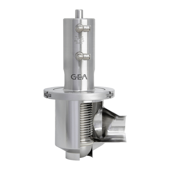
Page 15: Description
Description Design of the Valve Description Design of the Valve Fig.2: Main components on the valve Designation Housing Internal assembly Actuator Clamp (safety device) 430BAL012727EN_1 03.01.2018... -
Page 16: Valve Identification
Description Valve Identification Valve Identification Reference numbers from the following number systems are assigned to each part of components from GEA Aseptomag AG. The reference numbers can be used to clearly identify a component and its composition. Number Designation Description... - Page 17 Description Valve Identification Fig.3: Designations on the valve Example Position Details V-50-1001 Valve Drawing number of valve housing housing 1.4435 TC 333937 Material and re-stamping details 0548 10 Valve Serial number of valve housing housing V-50-1004 Clamp Number of clamp drawing V-50-2664 Internal Drawing number of internal assembly...
-
Page 18: Sealing Concepts
Description Sealing Concepts Sealing Concepts 3.3.1 System “without valve seat gasket” • Undivided valve disc • Metallic seal (not leakage-free) Fig.4: System “without valve seat gasket” 3.3.2 "Shrink-on Fit" Version • Undivided valve disc • For hard sealing materials such as TEFASEP, PTFE or reinforced PTFE Fig.5: "Shrink-on Fit"... - Page 19 Description Fig.6: "Divisible" version - for hard sealing materials Concept for Elastomer sealing materials • Divisible valve disc • For elastomer sealing materials such as EPDM (TVE) • Form-gasket with moulded-on retention flag Fig.7: "Divisible" version - for elastomer sealing materials 430BAL012727EN_1 03.01.2018...
-
Page 20: Transport And Storage
Transport and storage Storage conditions Transport and storage Storage conditions The valves, valve inserts or spare parts should be stored in a dry place, free of vibrations and dust, and protected from light. To avoid damage, leave the components in their original packaging if possible. If, during transport or storage, the valve is going to be exposed to temperatures ≤... -
Page 21: Technical Data
Technical data Technical data Technical data Technical data Operating data (for valve with sealing materials Tefasep and silicone) Max. operating temperature 150 °C (302 °F) Max. sterilisation temperature 160 °C (320 °F) for max. 30 min. Max. product pressure 5 ... 6 bar (others on request) Control air pressure, actuator 6 bar, max. -
Page 22: Determination Of Closing Pressure
Technical data Determination of closing pressure Compressed air supply Compressed air supply 6 bar, compressed air filtered (at least 0,5 µm), oil-free. Cleaning Cleaning The valve is suitable for CIP cleaning (Cleaning in Place) Recommended cleaning speed At least 2 m/s in the valve Sterilisation Sterilisation... - Page 23 Technical data Calculate: Supplied air pressure x rear component of the regulation ratio = closing pressure Example: 6 bar x 0.841 = 5.05 bar ® Closing pressure is determined. 430BAL012727EN_1 03.01.2018...
-
Page 24: Assembly And Installation
Assembly and installation Safety instructions Assembly and installation Safety instructions Dangerous situations during assembly can be avoided by safety-conscious and proactive behaviour of the staff. For installation, the following principles apply: • Only properly qualified staff is allowed to install, assemble and set the valve into operation. -
Page 25: Welding Post-Treatment
Assembly and installation Pneumatic connections Caution! If pipes contain liquids, these can spurt out when the pipes are opened. Danger of injury as a result of hot or aggressive liquids. ► Drain all pipe system elements that lead to the valve location and, if necessary, clean or rinse them. -
Page 26: Establishing The Compressed Air Supply
Assembly and installation Pneumatic connections Air requirement for opening the actuators LL Actuator Reference Nominal width of valve stroke Requirement [mm] DN 15 OD 3/4" PA30 LL DN 25 OD 1" PA30 LL DN 40 OD 1 1/2" PA40 LL 12.5 DN 50 OD 2"... -
Page 27: Electrical Connections
Therefore we recommend using a pneumatic or electro-pneumatic pressure regulating unit. The following versions can be ordered as standard from the manufacturer: Versions pressure regulating unit. Material Number Functional Description GEA Aseptomag AG 0982.50369 single-acting pneumatic V-25-4471 0982.50374 double-acting pneumatic V-25-4522 0982.50379... -
Page 28: Start-Up
Start-up Safety instructions Start-up Safety instructions Initial commissioning For initial commissioning, the following principles apply: • Take protective measures against dangerous contact voltages in accordance with pertinent regulations. • The valve must be completely assembled and correctly adjusted. All screw connections must be securely tightened. -
Page 29: Operation And Control
Operation and control Safety instructions Operation and control Safety instructions Dangerous situations during operation can be avoided by safety-conscious and proactive behaviour of the staff. For operation, the following principles apply: • Monitor the valve during the operation. • Safety devices must not be changed, removed or taken out of service. Check all safety devices at regular intervals. -
Page 30: Cleaning
Cleaning Cleaning Cleaning Cleaning The valve is suitable for CIP (Cleaning in Place); recommended cleaning speed in the valve is at least 2 m/s. All parts in contact with product must be cleaned at regular intervals. Always observe the safety data sheets issued by the cleaning agent manufacturers. Only use cleaning agents which do not cause damage to the seals and the inner parts of the valve. - Page 31 Cleaning The ultimate temperatures, chemicals, concentrations and contact time to be used must be determined by the plant operator along with its chemical supplier. 430BAL012727EN_1 03.01.2018...
- Page 32 Maintenance Safety instructions Maintenance 10.1 Safety instructions Maintenance and repair Before starting any maintenance and repair work on the electrical devices of the valve, carry out the following steps in accordance with the "5 safety rules": • Isolate from the power supply •...
- Page 33 Maintenance Inspections • Do not climb on the valve. Use suitable access aids and working platforms. • Mark the lines (if unmarked) prior to disassembly to ensure they are not confused when re-assembling. • Protect open line ends with blind plugs against ingress of dirt. •...
- Page 34 Section 10.5, Page 37. 10.4 List of tools List of tools (in alphabetical order) Material Number Tools Figure Intended Purpose GEA Aseptomag AG Valves Pressurizing tool 0980.50003 DN 10 - DN 80 DN 10 - DN 80 S-12-0010 Inspection of metal bellows Fig.9...
- Page 35 Maintenance List of tools List of tools (in alphabetical order) Material Number Tools Figure Intended Purpose GEA Aseptomag AG Pressure control valve Inspection of metal 9999.10090 bellows Ø 6 mm Fig.12 Flexible head spanner PA80-135 0980.10009 Ø60-90mm, Remove/fit assembly S-12-0332 spring Pin Ø...
- Page 36 Maintenance List of tools List of tools (in alphabetical order) Material Number Tools Figure Intended Purpose GEA Aseptomag AG Assembly tool PA30-210 0981.50008 Spring assembly Remove/insert spring S-12-0209 PA30-210 assembly Fig.18 Assembly tool PA30-210 5050.51064 Clamping device Hold cylinder S-12-0005 PA30-210 Fig.19...
- Page 37 Maintenance Prior to disassembly List of tools (in alphabetical order) Material Number Tools Figure Intended Purpose GEA Aseptomag AG Vice For divisible internal with soft jaws or assemblies and equivalent protective Actuators jaws Fig.23 Protective gloves, Remove/fit hard valve heat-resistant seat seals Fig.24...
- Page 38 Maintenance Disassembling and Assembling the Valve Drain all pipe system elements that lead to the valve and, if necessary, clean or rinse, and also depressurize them. Shut off the control air supply. Disconnect the power supply. ® Disassembly has been prepared. 10.6 Disassembling and Assembling the Valve 10.6.1...
- Page 39 Maintenance Disassembling and Assembling the Valve Fig.29: Loosening the clamp screw ! Ensure that you can move the clamp by hand and without much effort before carrying out the next step. If this is not the case, carefully hit the clamp segments with a plastic mallet until the pressure is released and the clamp can easily be moved afterwards.
- Page 40 Maintenance Disassembling and Assembling the Internal Assembly • Hex socket key Carry out the following steps: Install the valve in the reverse order of disassembly, see Section 10.6.1, Page 38. ! Note “Torques for clamp”, see Section 10.6.3, Page 40 Test the function of the valve after assembling.
- Page 41 Maintenance Disassembling and Assembling the Internal Assembly Fig.31: Extend the piston rod with the groove upwards. Lift the internal assembly slightly to detach it from the T-slot on the drive spindle. Fig.32: Unhooking the internal assembly Remove the housing seal without a tool. ! Do not damage the sealing surfaces on the housing and internal assembly.
- Page 42 Maintenance Removing and Installing the "Shrunk-on” Valve Seat Seal Hint! Statically loaded gaskets in the product-contacting area are generally not lubricated. To facilitate assembly (better gliding properties and securing against turning), this type of elastomer seal may, however, be wetted using a food-grade lubricant. ! Wetting elastomer gaskets is not permitted when they are used in ATEX applications! 10.8...
- Page 43 Maintenance Removing and Installing the "Shrunk-on” Valve Seat Seal Fig.34: Cut through valve seat seal Take out the cut valve seat seal. ® The valve seat seal has been removed. 10.8.2 Fitting the Shrunk-on Valve Seat Seal Tools required: • Oven (no microwave) •...
- Page 44 Maintenance Removing and Installing the "Divisible System" Valve Seat Seal Fig.36: Place the valve seat seal into the groove Then use both thumbs/palms to press the valve seat seal in place in the radial groove. ! Make sure the valve seat seal "clicks" into the radial groove. The audible clicking noise indicates that the seal has been fitted correctly.
- Page 45 Maintenance Removing and Installing the "Divisible System" Valve Seat Seal 10.9.1 Removing the Divisible Valve Seat Seal For information on valve seat seals, see Section 3.3, Page 18 Tools required: • Ratchet with square socket drive ½" • Socket wrench bit •...
- Page 46 Maintenance Removing and Installing the "Divisible System" Valve Seat Seal TVE & TVPV Fig.40: Removing seal(s) Divisible valve disc, valve seat seal TEFASEP Divisible valve disc, valve seat seal EPDM (form seal) TVPV Divisible valve disc, valve seat seal PTFE reinforced (form seal) ®...
- Page 47 Maintenance Carrying out the “Internal Assembly” Leak Test (Bubble Test) 10.9.3 Torques for Divisible Valve discs Thread size of valve Valve size Torque [Nm] disc DN15 DN25 M8 x 1 DN40 M10 x 1.25 DN50 M12 x 1.25 DN65 M12 x 1.25 DN80 M12 x 1.25 DN100...
- Page 48 Maintenance Carrying out the “Internal Assembly” Leak Test (Bubble Test) Fig.42: Attach clamping arms Pull the valve cap against the seal by means of the star grip on the pressurizing tool (hand-tight). Fig.43: Secure internal assembly Apply max. 3 bar of compressed air to the pressurizing tool. ! Air pressures >...
- Page 49 Maintenance Disassembling and Assembling Actuator PA30LL - PA60LL Fig.44: Water bath Remove the internal assembly from the pressurizing tool in reverse order. ® This completes the leak test. 10.11 Disassembling and Assembling Actuator PA30LL - PA60LL 10.11.1 Disassembling Actuator PA30LL - PA60LL Tools required: •...
- Page 50 Maintenance Disassembling and Assembling Actuator PA30LL - PA60LL Fig.45: Attach the clamping device at the actuator Grip the actuator in the vice using the clamping device. Fig.46: Clamp the clamping piece in the vice ® Disassembly has been prepared. PA30LL - PA60LL: dismantling the actuator Carry out the following steps: Remove the circlip with Seeger circlip pliers.
- Page 51 Maintenance Disassembling and Assembling Actuator PA30LL - PA60LL Fig.47: Removing the circlip Use the assembly tool for the spring assembly to pull the drive components upwards and out of the cylinder. Fig.48: Pull the components out of the cylinder Carefully slip off the securing elements sleeve and piston disc from the piston rod.
- Page 52 Maintenance Disassembling and Assembling Actuator PA80LL - PA180LL ! Pay attention to the alignment of the piston disc (asymmetrical design) already when disassembling. Fig.49: Remove securing elements and actuator components ® Actuator PA30LL - PA60LL has been disassembled. 10.11.2 Assembling Actuator PA30LL - PA60LL Hint! Pay attention to the following points when assembling the actuator: •...
- Page 53 Maintenance Disassembling and Assembling Actuator PA80LL - PA180LL • Assembly tool for spring assembly • Assembly tool for O-ring • Vice Preparing disassembly Carry out the following steps: Prepare disassembly, see Page 49. ® Disassembly has been prepared Removing assembly spring Carry out the following steps: Turn the actuator base counter-clockwise using a flexible head spanner, see illustration.
- Page 54 Maintenance Disassembling and Assembling Actuator PA80LL - PA180LL Fig.52: Removing actuator base Use the assembly tool for the spring assembly to pull the drive components upwards and out of the cylinder. Fig.53: Pull the components out of the cylinder Carefully slip off the securing elements sleeve and piston disc from the piston rod.
- Page 55 Maintenance Disassembling and Assembling Actuator PA80LL - PA180LL Fig.54: Remove securing elements and drive components ® Actuator PA80LL - PA180LL has been disassembled. 10.12.2 Assembling Actuator PA80LL - PA180LL Hint! Pay attention to the following points when assembling the actuator: •...
- Page 56 Maintenance Disassembling and Assembling Actuator PA80LL - PA180LL Fig.55: Aligning hole to slot Insert the angled part of the assembly spring into the hole of the actuator base. Fig.56: Hooking in the assembly spring Turn the actuator base 360° counter-clockwise using a flexible head spanner. ®...
- Page 57 Prior to any work on the open valve, ensure that it has stopped operation, see Section 10.5, Page 37. The following information and values are based on the experience of GEA Aseptomag AG and apply for installations working in 2-shift operation.
- Page 58 Maintenance Checking the Feedback Unit Activities to be performed after 3 months (only after initial commissioning or after a process change) Component Activity to be performed Feedback Function check Check of mechanical parts and visual inspection of condition Pneumatic connections Leak test Electrical connections Visual inspection...
- Page 59 Maintenance Actuate the valve with compressed air. If provided, set the proximity switch for the actuated position. For reference regarding the stroke to be expected see the “Valve Stroke“ table Section 10.14.2, Page 59. ® The feedback unit has been set. Hint! If a control head is installed, the specifications of the respective operating instructions must be observed.
- Page 60 Alarms Malfunctions and remedies Alarms 11.1 Malfunctions and remedies Notice! Warning of damage to property/loss of product Ignoring malfunctions may cause considerable damage to property and loss of product. The safe operation of the valve in the event of a fault can no longer be taken for granted and in the worst case can result in a loss of sterility in the process.
- Page 61 Alarms Malfunction Cause Remedy • Check that the feedback • The feedback unit is not unit has been fitted fitted correctly. correctly. • The proximity switch is not Valve feedback not correct. • Check the position of the in the correct position or is proximity switch and re- defective.
- Page 62 Decommissioning Safety instructions Decommissioning 12.1 Safety instructions For shutting down, the following principles apply: • Switch off the compressed air. • Switch off the valve via the main switch. • Padlock the main switch (if fitted) in the off position to prevent it from being switched back on.
- Page 63 Appendix Lists Appendix 13.1 Lists 13.1.1 Abbreviations and terms Abbreviation Explanation ° Symbol for the grade of a scale [degrees] All degree data is assumed to be angle degrees unless explicitly specified otherwise. °C Unit of measurement of temperature [degree Celsius] °F Unit of measurement of temperature [degree Fahrenheit] AISI...
- Page 64 Appendix Abbreviation Explanation Unit of measurement of work [newton metre] Unit of torque 1 Nm = 0.737 lbft Pound-Force (lb) + Feet (ft) Normally Open; direction of action air-closing/spring-opening Outside diameter; short name for outside diameter for inch tubes according to DIN 11866-C Pneumatic actuator PTFE Polytetrafluoroethylene...
- Page 65 Appendix 430BAL012727EN_1 03.01.2018...
Need help?
Do you have a question about the Aseptomag GD and is the answer not in the manual?
Questions and answers