
Subscribe to Our Youtube Channel
Related Manuals for Pylontech UF5000 Series


Summary of Contents for Pylontech UF5000 Series
- Page 1 Rechargeable Li-ion Battery UF5000 Series Operation Manual Information Version: 1.0 5PMPA08-00204...
- Page 2 This manual introduces UF5000 from Pylontech. Please read this manual before use and follow the instructions carefully during the installation process. Any confusion, please contact Pylontech for advice and clarification.
-
Page 3: Table Of Contents
Contents Symbols ......................1 Safety Precautions ................... 3 Before Connecting ..................... 4 In Using ........................4 Introduction ....................... 5 Features ........................5 Specifications ....................... 6 Equipment interface ..................8 Safe Handling of Lithium Batteries ............13 Schematic diagram of solution ..............13 Labels ........................ -
Page 4: Symbols
1. Symbols Caution! Warning! Reminding. Safety related information. Risk of battery system failure or life cycle reduces. Do not reversely connect the positive and negative port. Do not place near open flame. Do not place at the children or pet touchable area. Warning electric shock. - Page 5 The certificate label for Safety by TÜV Rheinland. Label for Waste Electrical and Electronic Equipment (WEEE) Directive (2012/19/EU).
-
Page 6: Safety Precautions
2. Safety Precautions Reminding 1) It is important and necessary to read the user manual carefully before installing or using battery. Failure to do so or to follow any of the instructions or warnings in this document can result in death, serious injury, electrical shock or battery damage, potentially rendering the battery inoperable. -
Page 7: Before Connecting
DO NOT open, repair or disassemble the battery unless by staff from Pylontech or authorized by Pylontech. We do not undertake any consequences or related responsibility due to violation of safety operation or violation of design, production and equipment safety... -
Page 8: Introduction
3. Introduction UF5000 lithium iron phosphate battery is a new type of energy storage product developed and produced by Pylontech, which can provide reliable and high power for various types of equipment and systems. 3.1 Features 1) Built-in soft-start function which reduces current strike when the inverter needs to start from battery. -
Page 9: Specifications
3.2 Specifications (Unit: mm) - Page 10 In high(>40℃) or low temperature (<10℃) environments, the charging and discharging power of the battery system will be limited due to BMS operation logic. Operation Cycle Life is defined based on specific operation conditions. For more details, please consult check with Pylontech service team.
-
Page 11: Equipment Interface
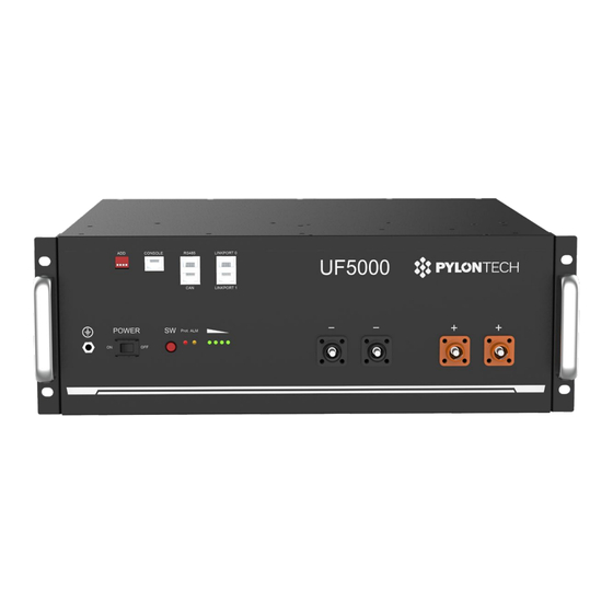
3.3 Equipment interface UF5000 front panel A. Grounding B. Add (Switch) C. Console D. RS485/CAN Point E. Link Port 0/1 F. Power Switch G. Start H. Protection(Prot.) J. Alarm(ALM) K. SOC Power Power Terminal(s) - Terminal(s)+ A. Grounding Point To connect the grounding cable. B. - Page 12 For instance: corresponding Dip1 Dip2 Dip3 Dip4 Status position of switch RS485:115200 CAN terminal resistance: connected RS485:9600 CAN terminal resistance: connected C. Console For the manufacturer or professional engineer to debug or service. Pin1 Pin2 Pin3 Pin4 Pin5 Pin6 Pin7 Pin8 232-TX 232-RX...
- Page 13 F. Power Switch ON: Power On. OFF: Power Off, for storage or shipping. G. Start (SW) ON: Press more than 0.5s to start the battery. OFF: Press more than 0.5s to turn off the battery. H. Protection Protection light: RED LED indicates that the battery is under BMS protection, combined with SOC LEDs to show which kind of protection in detail.
- Page 14 LED Status Indicators It`s important to check the detailed alarm/protection definitions according to the following table for trouble-shooting and maintenance service. Prote 75 ~ 50 ~ 25 ~ Condition Description ● ● ● ● ● ● Turn off All LED lighting until battery is Off. Power off ●...
- Page 15 BMS basic function Protection and alarm Management and monitor Charge/Discharge End Cells Balance Charge Over Voltage Intelligent Charge Model Discharge Under Voltage Charge/Discharge Current Limit Charge/Discharge Over Current Capacity Retention Calculate High/Low Temperature(cell/BMS) Administrator Monitor Short Circuit Operation Record Power Cable Reverse Soft start of inverter...
-
Page 16: Safe Handling Of Lithium Batteries
4. Safe Handling of Lithium Batteries 4.1 Schematic diagram of solution 4.2 Labels... -
Page 17: Safety Gear
4.3 Safety Gear It is recommended to wear the following safety gear when dealing with the battery. Insulated gloves Safety goggles Safety shoes 4.4 Tools Wire cutter Crimping modular plier Screwdriver NOTE Use properly insulated tools to prevent accidental electric shock or short circuits. -
Page 18: Installation And Operation
5. Installation and Operation Caution 1) According to local electric safety and installation policy, a suitable disconnection device between battery system and inverter could be installed. 2) All the installation and operation must follow local electric standards. 5.1 Package Items Unpack and check: 1) For battery module package: Battery Module... - Page 19 2) For External cable kits: NOTE: Power and communication cables connected to the inverter belong to an External Cable Kit, NOT included in battery carton box. They are in another extra small cable box. If there is anything missing, please contact the local dealer.
-
Page 20: Installation Location
5.2 Installation Location Caution If the ambient temperature is out of the operating range, the battery stops working to protect itself. The optimal temperature range for the battery module operation is 10°C to 40°C. Frequent exposures to harsh temperatures may deteriorate the performance and life of the battery. Make sure that the installation location meets the following conditions: 1) The area is completely waterproof. -
Page 21: Installation Direction
5.3 Installation Direction NOT allowed: Upside down Caution: DO NOT stack modules together directly. Installed only by two handles is NOT allowed. Recommended: Caution: Make sure that there is holder for more than 42kg weight at the bottom of each module. -
Page 22: Grounding
5.4 Grounding Grounding cables should be 6 AWG or higher yellow-green cables. After connection, the resistance from battery grounding point to Ground connection point of room or installed place should be less than 0.1 Ω. 1) There should be direct metal-to-metal contact between the module surface and the rack surface. -
Page 23: Installing Batteries Into The Cabinet Or Rack
5.5 Installing batteries into the cabinet or rack Put the battery modules into the cabinet and connect the cables. 1) Put the battery into the cabinet. 2) Fasten the 4 screws for each module. 3) Connect the cables between battery modules as shown. 4) Connect the cables to inverter. -
Page 24: Stacking The Batteries With Brackets
5.6 Stacking the batteries with brackets 1) Install 2 brackets on both the front and back sides of the battery as follows. 2) Stack the batteries together aligning 4 location holes. And lock the 4 buckles respectively. NOTE: Maximum 3 batteries are allowed for stacking in one vertical row due to the load-carrying capability of the brackets. - Page 25 3) Connect the cables between battery modules as shown. 4) Connect the cables to inverter.
-
Page 26: Installation Of The Wall Mount Rack
10 kg. The supporting ground or mounted wall must be strong to hold the overall weight of the battery system (about 136 kg of 3 batteries’ system). NOTE After installation, DO NOT forget to register online for full warranty: www.pylontech.com.cn/service/support... -
Page 27: Suitable Disconnection Device
5.8 Suitable disconnection device It is recommended to have a disconnection device for protection between battery system and inverter: 1) The rated voltage shall be ≥60VDC. DO NOT use an AC breaker. 2) The rated current should match with system design. The following factors should be considered: ... - Page 28 2) The one with empty Link Port 0 is the Master Battery Module, others are slaves (1 master battery configuring maximum slave batteries). Link Port 0 3) Press the red SW button of master battery to power on. After the master battery LED turns on, the LEDs on all the slave batteries will be on at the same time.
-
Page 29: Turning Off
NOTE: 1) After the battery module is powered on, the soft-start function takes 3 seconds to activate. When the soft start is complete, the battery is ready for high power output. 2) When connecting modules with different SOC/voltage in parallel during expansion or replacement, it is recommended to maintain the system in IDLE for ≥15 minutes or till the SOC LEDs become similar (≤1dot difference) before normal operation. -
Page 30: Trouble Shooting
6. Trouble shooting Communication related problems Unable to communicate with inverter on compatible list. Possible conditions: 1) RS485: baud rate. Check the dip switch1, set to correct one, and restart. 2) CAN: pin definitions. Try to connect the CAN-H, L, GND only and do not connect other pins to the inverter, using the correct cable. - Page 31 c) Current: If the current exceeds 100 A, the battery protection will be activated. Solution: Check whether current is too large, and if it is, change the settings on power supply side. d) High Voltage: If the charging voltage is above 57.6 V, battery protection will be activated.
- Page 32 setting of the inverter or charger, the charge voltage should be 56~56.8 VDC; Check whether the communication between battery system and inverter is established; Check whether the ADD switch on battery module is set correctly. Under this condition, the BMS remains functional without damage. Just leave the module switched OFF and wait for the battery voltage to drop down naturally (15 minutes) and then restart.
-
Page 33: Emergency Situations
The battery module is wet or 2. DO NOT let people access it, submerged in water. Batteries and contact Pylontech or an authorized dealer for technical support. Damaged batteries are dangerous If the battery pack seems to be... -
Page 34: Remarks
8. Remarks 8.1 Recycle and disposal. If a battery (normal condition or damaged) needs disposal or needs recycling, follow the local recycling regulation (i.e. Regulation (EC) Nº 1013/2006 among European Union) to process, and use the best available techniques to achieve a relevant recycling efficiency. - Page 36 Pylon Technologies Co., Ltd. 5/F, No.71-72, Lane 887, ZuChongzhi Road, China (Shanghai) Pilot Free Trade Zone Pudong, Shanghai 201203, China T+86-21-51317699 | +86-21-51317698 service@pylontech.com.cn...
Need help?
Do you have a question about the UF5000 Series and is the answer not in the manual?
Questions and answers
My UF5000 connected to sun deye 8k and as per battery user guide the charge voltage VDC is 56~ 56.8 No float voltage mentioned in the user guide share therefore shall I disable float charge option in deye batter settings Please advice?