Rockwell Automation Allen-Bradley PowerFlex 400 Product Information
Adjustable frequency ac drive
Hide thumbs
Also See for Allen-Bradley PowerFlex 400:
- Quick start manual (52 pages) ,
- Installation instructions manual (208 pages)
Advertisement
Quick Links
Product Information
Original Instructions
PowerFlex 400 Adjustable Frequency
AC Drive
Catalog Number 22C
ATTENTION:
• Before installing, configuring, operating, or maintaining this product, read
this document and the documents that are listed in the Additional Resources
section for installing, configuring, or operating equipment. Users should
familiarize themselves with installation and wiring instructions in addition to
the requirements of all applicable codes, laws, and standards.
• Installation, adjustments, putting into service, use, assembly, disassembly, and
maintenance shall be carried out by suitably trained personnel in accordance with
the applicable code of practice.
• If this equipment is used in a manner that is not specified by the manufacturer,
the protection that is provided by the equipment may be impaired.
• Solid-state equipment has operational characteristics that differ from those of
electromechanical equipment. Safety Guidelines for the Application, Installation,
and Maintenance of Solid-state Control Installation Instructions, publication
SGI-1.1, available from your local Rockwell Automation sales office or online at
rok.auto/literature
describes some important differences between solid-state
equipment and hard-wired electromechanical devices.
ATTENTION: Do not install, configure, operate or maintain this product until you
have read the product documentation and the documents in the Additional
Resources section for installing, configuring, operating or maintaining equipment.
To get the product documentation go to
rok.auto/literature
sales office or Rockwell Automation representative.
ATTENTION : Ne pas installer, configurer, exploiter ou maintenir ce produit tant que
vous n'avez pas lu sa documentation et les documents de la rubrique Documents
connexes pour l'installation, la configuration, l'exploitation et la maintenance de
l'équipement. Pour obtenir de la documentation, rendez-vous sur le site
rok.auto/literature
ou contactez votre agence commerciale Rockwell Automation
locale ou son représentant.
ACHTUNG: Für die Installation, Konfiguration, den Betrieb und die Wartung dieses
Produkt lesen Sie sich bitte zunächst die Produktdokumentation sowie die
Dokumente im Abschnitt "Weitere Informationen" durch. Die entsprechende
Produktdokumentation finden Sie unter
rok.auto/literature
lokales Vertriebsbüro bzw. einen Rockwell Automation-Mitarbeiter.
ATENCIÓN: No instale, configure, opere ni mantenga este producto hasta que haya
leído la documentación del producto y los documentos en la sección Recursos
adicionales para la instalación, configuración, operación o mantenimiento de
equipo. Para conseguir la documentación, diríjase a
contacto con su oficina regional de ventas o representante de Rockwell Automation.
ATENÇÃO: Não instale, configure, opere ou mantenha este produto até que você leia
a documentação do produto e os documentos na seção Recursos adicionais para a
instalação, configuração, operação ou manutenção do equipamento. Para conseguir
a documentação, visite
rok.auto/literature
ou entre em contato con seu escritório
de vendas regional ou representante da Rockwell Automation.
ATTENZIONE: Non installare, configurare, attivare o riparare questo prodotto senza
avere prima letto la relativa documentazione nonchè i documenti indicati nella
sezione Ulteriori Risore riguardanti l'installazione, la configurazione, l'attivazione o la
riparazione dell'apparecchiatura. Per la documentazione sul prodotto visitare il sito
rok.auto/literature
o contattare l'ufficio vendite o il rappresentate Rockwell
Automation di zona.
rok.auto/literature
Web
:
,
,
rok.auto/literature
rok.auto/literature
UWAGA: Nie instaluj i nie uruchamiaj tego urządzenia dopóki nie zapoznasz się z
instrukcją użytkownika produktu. Aby uzyskać dokumentację produktu przejdź do
strony internetowej
rok.auto/literature
lub skontaktuj się z lokalnym biurem
sprzedaży lub przedstawicielstwem firmy Rockwell Automation.
UPOZORŇENÍ: Neprovádějte instalaci, konfiguraci, provoz ani údržbu, pokud jste
dosud nepřečetli dokumentaci k produktu a dokumenty obsažené v sekci Doplňující
informace pro instalaci, konfiguraci, provoz a údržbu. Tuto dokumentaci můžete
získat na
rok.auto/literature
nebo od obchodního zástupce společnosti Rockwell
Automation.
Summary of Changes
This publication contains new or updated information. Changes throughout this revision are
marked by change bars, as shown to the left of this paragraph.
Mounting Considerations
• Mount the drive upright on a flat, vertical, and level surface.
Frame
Screw Size
Screw Torque
C
M5 (#10...24)
2.45...2.94 N•m (22...26 lb•in)
D
M8 (5/16 in.)
6.0...7.4 N•m (53.2...65.0 lb•in)
E
M8 (5/16 in.)
8.8...10.8 N•m (78.0...95.3 lb•in)
F
M10 (3/8 in.)
19.6...23.5 N•m (173.6...208.3 lb•in)
G
M12 (1/2 in.)
33.5...41.0 N•m (296.5...362.9 lb•in
H
M12 (1/2 in.)
33.5...41.0 N•m (296.5...362.9 lb•in)
• Protect the cooling fan by avoiding dust or metallic particles.
• Do not expose to a corrosive atmosphere.
• Protect from moisture and direct sunlight.
Minimum Mounting Clearances
Vertical mounting is shown. If mounting horizontally, apply the same clearances plus 50 mm
(2.0 in.) clearance from the top and bottom of the enclosure to allow for proper airflow.
Frame C Mounting Clearances
120 mm
(4.7 in.)
120 mm
(4.7 in.)
Closest object that
may restrict airflow
through the drive
heatsink and
chassis
120 mm
(4.7 in.)
120 mm
(4.7 in.)
Mounting Option A
No clearance is required between drives.
Frames D, E, and F Mounting Clearances
Frames D and E
50 mm
(2.0 in.)
Frames G and H Mounting Clearances
or contact your local
oder kontaktieren Sie Ihr
rok.auto/literature
o póngase en
Ambient Operating Temperatures
Frame
Ambient Temperature
Minimum
C
-10 °C (14 °F)
-10 °C (14 °F)
D, E, F, G, H
-10 °C (14 °F)
(1)
Frame C drives require installation of the PowerFlex® 400 IP30/NEMA 1/UL Type 1 option kit to achieve this rating.
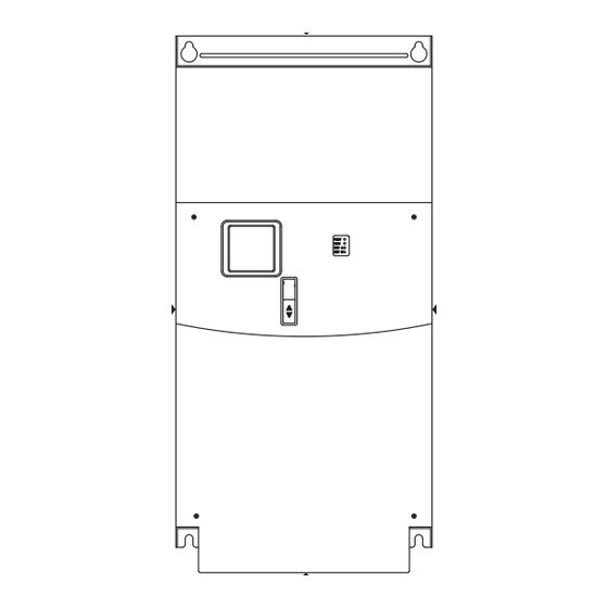
Drive Dimensions
PowerFlex 400 Frames
,
Ratings are in kW and HP.
.
rok.auto/literature
Output Power
.
kW
HP
2.2...7.5
3...10
11...15
15...20
18.5...22
25...30
30...37
40...50
45...75
60...100
90...110
125...150
132...160
200...250
200...250
300...350
PowerFlex 400 Frames C...H
Dimensions are in mm and (in.). Weights are in kg and (lb).
IP20/NEMA/UL Type Open
A
D
E
B
Frame A
C
130.0 (5.1)
D
250.0 (9.84)
E
370.0 (14.57)
F
425.0 (16.73)
G
425.0 (16.73)
H
529.2 (20.83)
(1)
Weights include HIM and standard I/O.
Fuses and Circuit Breakers
See the PowerFlex 400 Adjustable Frequency AC Drive for Fan and Pump Applications User Manual,
25 mm
publication
22C-UM001
(1.0 in.)
Fuses and Circuit Breakers – UL 61800-5-1 Applications
120 mm
(4.7 in.)
Catalog
Output
Number
Ratings
kW HP
120 mm
(4.7 in.)
200...240V AC (±10%) — 3-phase Input, 0...230V 3-phase Output
22C-B012N103 2.2 3.0 12
22C-B017N103 3.7 5.0 17.5 180...265 8.8
120 mm
22C-B024N103 5.5 7.5 24
(4.7 in.)
22C-B033N103 7.5 10
120 mm
(4.7 in.)
22C-B049A103 11
Mounting Option B
22C-B065A103 15
22C-B075A103 18.5 25 75
22C-B090A103 22 30 81
22C-B120A103 30 40 120 180...265 51.6 124 175 —
22C-B145A103 37 50 130 180...265 62.4 150 200 —
Frame F
250 mm
(9.8 in.)
150 mm
(6.0 in.)
50 mm
50 mm
(2.0 in.)
(2.0 in.)
150 mm
150 mm
(6.0 in.)
(6.0 in.)
300 mm
(11.8 in.)
300 mm
300 mm
(11.8 in.)
(11.8 in.)
300 mm
(11.8 in.)
Enclosure Rating
Minimum Mounting
Clearances
Maximum
+45 °C (113 °F)
IP20/UL Open Type
Use Mounting Option A
Use Mounting Option B
(1)
IP30/NEMA 1/UL Type 1
+50 °C (122 °F) IP20/UL Open Type
Use Mounting Option B
+45 °C (113 °F)
IP30/NEMA 1/UL Type 1
See
Frames D, E, and F Mounting
Clearances
Mounting Clearances
Frame Size
200...240V AC Input
400...480V AC Input
C
C
D
C
D
D
E
E
—
E
—
F
—
G
—
H
Flange Mount for Frame C
IP20/66 (NEMA Type 1/4X/12)
300
C
(11.81)
325
(12.8)
24.5
(0.96)
B
C
D
E
260.0 (10.2)
180.0 (7.1)
116.0 (4.57)
246.0 (9.7)
436.2 (17.7)
206.1 (8.11)
226.0 (8.90)
383.4 (15.09)
605.5 (23.84)
259.2 (10.21)
335.0 (13.19)
567.4 (22.34)
850.0 (33.46)
264.0 (10.39)
381.0 (15.0)
647.5 (25.49)
892.0 (35.12)
264.0 (10.39)
381.0 (15.0)
819.5 (32.26)
1363.8 (53.69)
358.6 (14.12)
480.0 (18.90)
1119.0 (44.06)
for fuses and circuit breakers for non-UL applications.
Input Ratings
Branch Circuit Protection
Voltage
140M/140MT
Min
Range
Motor
Enclosure
Protectors
Volume
(2) (3)
(in.
180...265 6.5
15.5 20 140M-F8E-C16
100-C23
5098
100-E26
21
30 140M-F8E-C25 100-C37
5098
100-E38
180...265 10.9 26.1 35 140M-F8E-C32 100-C37
5098
100-E38
33
180...265 14.4 34.6 45 140M-F8E-C45 100-C43
5098
100-E40
15
49
180...265 21.3 51
70 —
100-C60
—
100-E65
20 65
180...265 28.3 68
90 —
100-C85
—
100-E80
180...265 32.5 78
100 —
100-E96 —
180...265 38.3 92
125 —
100-E116 —
100-E190 —
100-E190 —
Fuses and Circuit Breakers – UL 61800-5-1 Applications (Continued)
Catalog
Output
Input Ratings
Number
Ratings
kW HP
Voltage
Range
50 mm
380...480V AC (±10%) — 3-phase Input, 0...460V 3-phase Output
(2.0 in.)
22C-D6P0N103 2.2 3.0 6
340...528 6.3
22C-D010N103 4.0 5.0 10.5 340...528 10.9 13
22C-D012N103 5.5 7.5 12
340...528 11.9 14.2 20 140M-D8E-C16
22C-D017N103 7.5 10
17
340...528 15.3 18.4 25 140M-D8E-C20
22C-D022N103 11
15
22
340...528 19.2 23
22C-D030N103 15
20 27
340...528 25.8 31
22C-D038A103 18.5 25 38
340...528 33.3 40
22C-D045A103 22 30 45.5 340...528 39.1 47
22C-D060A103 30 40 54
340...528 53.3 64
22C-D072A103 37 50 72
340...528 60.7 73
22C-D088A103 45 60 88
340...528 74.9 90
22C-D105A103 55 75 105 340...528 89
22C-D142A103 75 100 128 340...528 124.8 150 200 —
22C-D170A103 90 125 170 340...528 142 170 250 —
22C-D208A103 110 150 208 340...528 167
22C-D260A103 132 200 260 340...528 196
22C-D310A103 160 250 290 340...528 242 290 400 —
22C-D370A103 200 300 370 340...528 304 365 500 —
22C-D460A103 250 350 410 340...528 387 465 600 —
(1)
Recommended Fuse Type: UL Class J, CC, T, or Type BS88; 600V (550V) or equivalent.
(2)
The AIC ratings of the Bulletin 140M/140MT devices can vary. See Motor Protection Circuit Breaker and Motor Circuit
Protector Specifications Technical Data, publication
(3)
Manual Self-protected (Type E) Combination Motor Controller, UL Listed for 208 Wye or Delta, 240 Wye or Delta,
480Y/277, or 600Y/347. Not UL Listed for use on 480V or 600V Delta/Delta, corner ground, or high-resistance ground
systems.
(4)
When using a Manual Self-protected (Type E) Combination Motor Controller, the drive must be installed in a ventilated
or non-ventilated enclosure with the minimum volume specified in this column. Application-specific thermal
considerations may require a larger enclosure.
Wiring
See the PowerFlex 400 Adjustable Frequency AC Drive for Fan and Pump Applications User Manual,
and
Frames G and H
publication
22C-UM001
for instructions on how to wire the power terminals and control terminals.
Power Terminal Blocks
R/L1 S/L2 T/L3 U/T1 V/T2 W/T3 P2 P1
DC–
DC+
BR+
BR–
R/L1 S/L2T/L3
P1 P2 DC–
R/L1 S/L2 T/L3 P1
P2 DC– U/T1 V/T2 W/T3
Frame F
244
(9.61)
R/L1S/L2 T/L3 P1 P2 DC– U/T1 V/T2 W/T3
105.8
138.2
(4.17)
(5.44)
Frame H
Ship
(1)
Weight
4.33 (9.5)
14.0 (30.9)
51.2 (112.9)
(1)
Description
Terminal
88.0 (194.0)
R/L1, S/L2, T/L3 3-phase Input
106 (233.7)
U/T1
To Motor U/T1
177 (390.2)
V/T2
To Motor V/T2
W/T3
To Motor W/T3
P2, P1
DC Bus Inductor Connection
- The C Frame drive is shipped with a jumper between Terminals P2 and P1.
- Remove this jumper only when you connect a DC Bus Inductor.
- The drive cannot power up without a jumper or inductor connected.
DC+, DC-
DC Bus Connection (Frame C Drives)
P2, DC-
DC Bus Connection (Frame D, E, and F Drives)
BR+, BR-
Not used
Safety Ground – PE
Power
Dissipation
(1)
Important: Terminal screws may become loose during shipment. Verify that all terminal screws are tightened to the
IP20 Open
recommended torque before you apply power to the drive.
Watts
(4)
Power Terminal Block Specifications
3
)
Frame
Maximum Wire Size
C
2
8.4 mm
(8 AWG)
D
2
33.6 mm
(2 AWG)
146
E
2
33.6 mm
(2 AWG)
(rating 480V, 37...45 kW
[50...60 HP])
207
E
2
107.2 mm
(4/0 AWG)
(rating 240V, 30...37 kW
266
[40...50 HP] and 480V,
55...75 kW [75...100 HP])
359
F
2
152.5 mm
G
2
152.5 mm
488
H
2
253.0 mm
650
(1)
Maximum/Minimum size that the terminal block accepts. These are not recommendations. If national or local codes
require sizes outside this range, lugs may be used.
734
778
1055
1200
Branch Circuit Protection
Power
Dissipation
140M/140MT
Min
IP20 Open
Motor
Enclosure
Watts
Protectors
(4)
Volume
(2) (3)
3
(in.
)
7.5
10 140M-D8E-C10
100-C09
5098
105
140MT-D9E-C10
100-E09
20 140M-D8E-C16
100-C16
5098
171
140MT-D9E-C16
100-E16
100-C23
5098
200
140MT-D9E-C16
100-E26
100-C23
5098
267
140MT-D9E-C20
100-E26
30 140M-F8E-C32 100-C30
5098
329
100-E30
40 140M-F8E-C32 100-C37
5098
435
100-E38
50 140M-F8E-C45 100-C60
9086
606
100-E65
60 —
100-C60
—
738
100-E65
80 —
100-C85
—
664
100-E80
100 —
100-C85
—
1019
100-E80
125 —
100-E116 —
1245
107 150 —
100-E146 —
1487
100-E190 —
2043
100-E265 —
2617
200 250 —
100-E265 —
3601
235 300 —
100-E305 —
3711
100-E400 —
4208
100-E400 —
4916
100-E580 —
6167
140-TD005
or 140M-TD002.
Frame C
Frame D
R/L1 S/L2 T/L3 P1
P2 DC– U/T1 V/T2 W/T3
Frame E:
480V
37...45 kW
(50...60 HP)
U/T1V/T2 W/T3
Frame E:
240V
480V
30...37 kW
55...75 kW
(40...50 HP)
(75...100 HP)
R/L1 S/L2 T/L3
P1 P2 DC–
U/T1 V/T2
W/T3
Frame G
R/L1 S/L2 T/L3
DC+
DC–
U/T1 V/T2 W/T3
Switch any two motor leads to change
=
forward direction.
Recommended Torque
(1)
(1)
Minimum Wire Size
2.9 N•m (26 lb•in)
2
1.3 mm
(16 AWG)
5.1 N•m (45 lb•in)
2
8.4 mm
(8 AWG)
2
5.6 N•m (49.5 lb•in)
3.5 mm
(12 AWG)
2
19.5 N•m (173 lb•in)
53.5 mm
(1/0 AWG)
19.5 N•m (173 lb•in)
2
(300 MCM)
85.0 mm
(3/0 AWG)
2
29.4 N•m (260 lb•in)
(300 MCM)
107.2 mm
(4/0 AWG)
2
40.0 N•m (354 lb•in)
(500 MCM)
152.0 mm
(300 MCM)
Advertisement

Related Manuals for Rockwell Automation Allen-Bradley PowerFlex 400


Summary of Contents for Rockwell Automation Allen-Bradley PowerFlex 400
- Page 1 30 140M-F8E-C32 100-C30 5098 100-E30 and Maintenance of Solid-state Control Installation Instructions, publication Frames G and H Mounting Clearances SGI-1.1, available from your local Rockwell Automation sales office or online at 22C-D030N103 15 20 27 340…528 25.8 31 40 140M-F8E-C32 100-C37...
- Page 2 Rockwell Otomasyon Ticaret A.Ş. Kar Plaza İş Merkezi E Blok Kat:6 34752, İçerenköy, İstanbul, Tel: +90 (216) 5698400 EEE Yönetmeliğine Uygundur Allen-Bradley, expanding human possibility, PowerFlex, Rockwell Automation, and TechConnect are trademarks of Rockwell Automation, Inc. Trademarks not belonging to Rockwell Automation are property of their respective companies.
Need help?
Do you have a question about the Allen-Bradley PowerFlex 400 and is the answer not in the manual?
Questions and answers