Table of Contents
Advertisement
Available languages
Available languages
Quick Links
www.abpowerflex.com
Adjustable Frequency AC Drive
Drehzahlveränderbarer Frequenzumrichter
Variateur de vitesse c.a.
Inverter CA a frequenza variabile
Variador de Frecuencia Ajustable de CA
AC Drive
Inversor CA de Freqüência Ajustável
FRN 6.xx
Quick Start
Kurzanleitung
Guide de mise en route
Avviamento rapido
Inicio Rápido
Snel aan de slag
Início Rápido
Advertisement
Table of Contents

Related Manuals for Rockwell Automation Allen-Bradley PowerFlex 4 FKN6 Series


Summary of Contents for Rockwell Automation Allen-Bradley PowerFlex 4 FKN6 Series
- Page 1 Adjustable Frequency AC Drive Drehzahlveränderbarer Frequenzumrichter Variateur de vitesse c.a. Inverter CA a frequenza variabile Variador de Frecuencia Ajustable de CA AC Drive Inversor CA de Freqüência Ajustável FRN 6.xx Quick Start Kurzanleitung Guide de mise en route Avviamento rapido Inicio Rápido Snel aan de slag Início Rápido...
-
Page 3: Quick Start
Quick Start PowerFlex 4 Adjustable Frequency AC Drive FRN 6.xx This Quick Start guide summarizes the basic steps needed to install, start-up and program the PowerFlex 4 Adjustable Frequency AC Drive. The information provided Does Not replace the User Manual and is intended for qualified drive service personnel only. -
Page 4: Mounting Considerations
English-2 Mounting Considerations • Mount the drive upright on a flat, vertical and level surface. Min. Panel Thickness Screw Size Screw Torque DIN Rail 1.9 mm (0.0747 in.) M4 (#8-32) 1.56-1.96 N-m (14-17 lb.-in.) 35 mm • Protect the cooling fan by avoiding dust or metallic particles. •... - Page 5 English-3 Specifications, Fuses and Circuit Breakers Drive Ratings Power Output Ratings Input Ratings Branch Circuit Protection Dissipation Catalog Number Voltage 140M Motor IP20 Open kW (HP) Amps Range kVA Amps Fuses Protectors Contactors Watts 100 - 120V AC (±10%) – 1-Phase Input, 0 - 230V 3-Phase Output 22A-V1P5N104 0.2 (0.25) 90-126 0.75 6.0...
-
Page 6: Power Wiring
English-4 Power Wiring Power Wire Rating Recommended Copper Wire Unshielded 600V, 75°C (167°F) THHN/THWN 15 Mils insulated, dry location Shielded 600V, 75°C or 90°C (167°F or 194°F) RHH/RHW-2 Belden 29501-29507 or equivalent Shielded Tray rated 600V, 75°C or 90°C (167°F or 194°F) RHH/RHW-2 Shawflex 2ACD/3ACD or equivalent Power Terminal Block (A Frame Shown) R/L1... -
Page 7: Control Terminal Block
English-5 Control Terminal Block Important: I/O Terminal 01 is Refer to the PowerFlex 4 P036 I/O Terminal 01 User Manual for more [Start Source] always a coast to stop input except Stop Stop information. when P036 [Start Source] is set to Keypad Per P037 Coast... -
Page 8: Prepare For Drive Start-Up
English-6 Prepare For Drive Start-Up ATTENTION: Power must be applied to the drive to perform the following start-up procedures. Some of the voltages present are at incoming line potential. To avoid electric shock hazard or damage to equipment, only qualified service personnel should perform the following procedure. -
Page 9: Integral Keypad
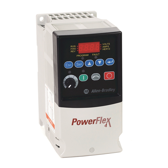
English-7 Integral Keypad Menu Description VOLTS Display Group (View Only) AMPS Consists of commonly viewed drive operating HERTZ conditions. PROGRAM FAULT Basic Program Group Consists of most commonly used programmable functions. Advanced Program Group Consists of remaining programmable functions. Fault Designator Consists of list of codes for specific fault conditions. -
Page 10: Viewing And Editing Parameters
English-8 See the PowerFlex 4 User Manual for more information on parameters. Viewing and Editing Parameters The last user-selected Display Group parameter is saved when power is removed and is displayed by default when power is reapplied. The following is an example of basic integral keypad and display functions. This example provides basic navigation instructions and illustrates how to program the first Program Group parameter. -
Page 11: Display Group Parameters
English-9 See the PowerFlex 4 User Manual for more information on parameters. Display Group Parameters Parameter Min/Max Display/Options d001 [Output Freq] 0.0/[Maximum Freq] 0.1 Hz d002 [Commanded Freq] 0.0/[Maximum Freq] 0.1 Hz 0.00/(Drive Amps × 2) d003 [Output Current] 0.01 Amps d004 [Output Voltage] 0/Drive Rated Volts 1 VAC... - Page 12 English-10 See the PowerFlex 4 User Manual for more information on parameters. Advanced Group Parameters Parameter Min/Max Display/Options Default A051 [Digital In1 Sel] 0/26 0 = “Not Used” 8 = “RampStop,CF” I/O Terminal 05 1 = “Acc 2 & Dec 2” 9 = “CoastStop,CF”...
-
Page 13: Fault Codes
English-11 See the PowerFlex 4 User Manual for more information on parameters. Parameter Min/Max Display/Options Default A103 [Comm Data Rate] 0 = “1200” 3 = “9600” 1 = “2400” 4 = “19.2K” 2 = “4800” 5 = “38.4K” A104 [Comm Node Addr] 1/247 A105 [Comm Loss Action] 0/3 0 = “Fault”... -
Page 14: Drive Dimensions
Frame A - 22-JBAA Frame B - 22-JBAB U.S. Allen-Bradley Drives Technical Support Tel: (1) 262.512.8176, Fax: (1) 262.512.2222, Email: support@drives.ra.rockwell.com, Online: www.ab.com/support/abdrives Publication 22A-QS001H-EN-P – October 2009 Supersedes October 2008 Copyright © 2009 Rockwell Automation, Inc. All rights reserved. - Page 15 Kurzanleitung Frequenzumrichter PowerFlex 4 FRN 6.xx In dieser Kurzanleitung wird beschrieben, wie Sie den Frequenzumrichter PowerFlex 4 installieren, in Betrieb nehmen und programmieren. Die hierin enthaltenen Informationen sind jedoch kein Ersatz für das Benutzer- handbuch und sind nur für qualifiziertes FU-Wartungspersonal vorgesehen. Genauere Informationen über den PowerFlex 4, einschließlich EMV-Hinweise, Anwendungsaspekte und die entsprechenden sicherheitstechnischen Hinweise, finden Sie im PowerFlex 4-Benutzerhandbuch, Publikation 22A-UM001…, unter...
- Page 16 Deutsch-2 Erläuterungen zum Aufstellen des FUs • Befestigen Sie den FU aufrecht an einer flachen, senkrechten und ebenen Fläche. Mindeststärke der Schraubengröße Anzugsmoment DIN-Schiene Montageplatte 1,9 mm M4 (#8-32) 1,56–1,96 Nm 35 mm • Das Kühlgebläse vor Staub und Metallpartikeln schützen. •...
- Page 17 Deutsch-3 Sicherungen und Leistungsschalter – Technische Daten FU-Nennwerte Verlust- Ausgangsnennwerte Eingangsnennwerte Netzstromleitungsschutz leistung Bestellnummer Spannungs- Siche- Motorschutz- Überbrückungs- IP20 offen kW (HP) bereich rungen schalter 140M schütze 100–120 V AC (±10 %) – Einphaseneingang, 0–230-V-AC-Dreiphasenausgang 22A-V1P5N104 0,2 (0,25) 90-126 0,75 6,0 140M-C2E-C10 100-C09 22A-V2P3N104 0,4 (0,5)
- Page 18 Deutsch-4 Netzanschluss Verdrahtungsnennwerte Empfohlener Kupferdraht Nicht abgeschirmt, 600 V, 75 °C THHN/THWN 0,4 mm, isoliert, für trockene Standorte Abgeschirmt, 600 V, 75 °C oder 90 °C RHH/RHW-2 Belden 29501-29507 oder gleichwertig Abgeschirmter Kabelkanal mit Nennwert 600 V, 75 °C oder 90 °C RHH/RHW-2 Shawflex 2ACD/3ACD oder gleichwertig Klemmenblock für den Netzanschluss (hier Baugröße A)
- Page 19 Deutsch-5 Steuerein- und Steuerausgänge Weitere Informationen dazu Wichtig: An E/A-Klemme 01 P036 E/A-Klemmenblock 01 finden Sie im PowerFlex 4- [Startquelle] erfolgt nur dann kein Auslauf, wenn Stopp Stopp Benutzerhandbuch. P036 [Startquelle] auf „3-Draht- Tastenblock Gemäß P037 Auslauf Steuerung“ eingestellt ist. Bei der 3-Draht Gemäß...
-
Page 20: Vor Dem Einschalten
Deutsch-6 Vorbereitung auf die FU-Inbetriebnahme ACHTUNG: Legen Sie zunächst Spannung an den FU an, um die im Folgenden beschriebenen Vorgänge für die Inbetriebnahme durchführen zu können. Im Gerät liegen allerdings Spannungen in der Höhe der Netzspannung an. Zur Vermeidung eines elektrischen Schlags bzw. von Geräteschäden sollten die folgenden Schritte nur von qualifiziertem Wartungspersonal durchgeführt werden. - Page 21 Deutsch-7 Integrierter Tastenblock Menü Beschreibung VOLTS Anzeige-Gruppe (nur zur Anzeige) AMPS Besteht aus häufig angezeigten HERTZ FU-Betriebszuständen. PROGRAM FAULT Grundsätzliche Programm-Gruppe Besteht aus häufig verwendeten programmierbaren Funktionen. Erweiterte Programm-Gruppe Besteht aus den restlichen programmierbaren Funktionen. Störung Besteht aus einer Auflistung von Codes für bestimmte Fehlerzustände.
- Page 22 Deutsch-8 Weitere Informationen zu Parametern finden Sie im PowerFlex 4-Benutzerhandbuch. Anzeigen und Bearbeiten von Parametern Beim Abschalten wird der zuletzt vom Benutzer gewählte Anzeige-Gruppe-Parameter gespeichert. Dieser wird standardmäßig beim nächsten Einschalten angezeigt. Es folgt ein Beispiel grundlegender Funktionen der integrierten Tastatur und der Anzeige. Dieses Beispiel enthält grundlegende Navigationsanweisungen und veranschaulicht, wie der erste Parameter der Programm-Gruppe programmiert wird.
- Page 23 Deutsch-9 Weitere Informationen zu Parametern finden Sie im PowerFlex 4-Benutzerhandbuch. Parameter der Anzeige-Gruppe Parameter Min./Max. Anzeige/Optionen d001 [Ausgangsfreq] 0,0/[Maximalfrequenz] 0,1 Hz d002 [Frequenzsollwert] 0,0/[Maximalfrequenz] 0,1 Hz 0,00/(FU-Strom A × 2) d003 [Ausgangsstrom] 0,01 A d004 [Ausgangsspannung] 0/FU-Nennspannung 1 V AC d005 [DC-Busspannung] Basierend auf 1 V DC...
- Page 24 Deutsch-10 Weitere Informationen zu Parametern finden Sie im PowerFlex 4-Benutzerhandbuch. Erweiterte Parametergruppe Werks- Parameter Min./Max. Anzeige/Optionen einstellung A051 [Wahl Dig. Eing1] 0/26 0 = „Nicht verw.“ 8 = „RampStop,CF“ E/A-Klemme 05 1 = „Besch 2 & Verz 2“ 9 = „AuslStop,CF“ A052 [Wahl Dig.Eing2] 2 = „Tippen“...
- Page 25 Deutsch-11 Weitere Informationen zu Parametern finden Sie im PowerFlex 4-Benutzerhandbuch. Werks- Parameter Min./Max. Anzeige/Optionen einstellung A103 [Komm.-Datenrate] 0 = „1200“ 3 = „9600“ 1 = „2400“ 4 = „19,2 K“ 2 = „4800“ 5 = „38,4 K“ A104 [Komm.-Knotenadr.] 1/247 A105 [Maßn KommVerlust] 0/3 0 = „Fehler“...
- Page 26 Baugröße A - 22-JBAA Baugröße B - 22-JBAB Technischer Support für FUs von Rockwell Automation Tel.: 02104/960-630, Fax: 02104/960-501, E-Mail: esupport1@ra.rockwell.com, Online: www.ab.com/support/abdrives Publikation 22A-QS001H-DE-P – Oktober 2009 Ersetzt Publikation vom Oktober 2008 Copyright © 2009 Rockwell Automation, Inc. Alle Rechte vorbehalten.
-
Page 27: Guide De Mise En Route
Guide de mise en route Variateur de vitesse c.a. PowerFlex 4 FRN 6.xx Ce guide de mise en route résume les étapes de base nécessaires à l’installation, la mise en service et la programmation du variateur de vitesse c.a. PowerFlex 4. Les informations fournies ne remplacent pas le manuel utilisateur et s’adressent uniquement au personnel qualifié... -
Page 28: Instructions De Montage
Français-2 Instructions de montage • Montez le variateur verticalement sur une surface plate, verticale et plane. Epaisseur minimale du panneau Taille des vis Couple de serrage Rail DIN 1,9 mm (0,0747 in.) M4 (n° 8-32) 1,56-1,96 Nm (14-17 lb.-in.) 35 mm •... - Page 29 Français-3 Spécifications, fusibles et disjoncteurs Caractéristiques nominales des variateurs Caractéristiques Caractéristiques Dissipation nominales de sortie nominales d’entrée Protection du circuit de dérivation thermique Référence Plage de Protections IP 20 ouvert kW (CV) tensions kVA A Fusibles moteur 140M Contacteurs (watts) Entrée monophasée 100–120 V c.a.
-
Page 30: Câblage De Puissance
Français-4 Câblage de puissance Section du câblage d’alimentation Conducteur de cuivre recommandé Non blindé 600 V, 75 °C (167 °F) THHN/THWN Isolation 0,38 mm, site sec Blindé 600 V, 75 °C ou 90 °C (167 °F ou 194 °F) RHH/RHW-2 Belden 29501-29507 ou équivalent Blindé, pour chemin de câble 600 V, 75 °C ou 90 °C (167 °F ou 194 °F) RHH/RHW-2 Shawflex 2ACD/3ACD ou équivalent... -
Page 31: Bornier De Commande
Français-5 Bornier de commande Pour plus d’informations, Important : la borne 01 des P036 Bornier d’E/S 01 reportez-vous au Manuel E/S est toujours une entrée d’arrêt [Source Démarrage] Arrêt Arrêt Utilisateur du PowerFlex 4. en roue libre, sauf quand P036 Clavier Selon P037 Roue libre... - Page 32 Français-6 Préparation de la mise en service du variateur ATTENTION : pour procéder à la mise en service du variateur, vous devez le mettre sous tension. Certaines des tensions présentes sont au potentiel de l’alimentation. Pour éviter tout risque d’électrocution ou de dégât matériel, la procédure suivante doit être exécutée uniquement par un personnel qualifié.
- Page 33 Français-7 Clavier intégré Menu Description VOLTS Groupe affichage (lecture seule) AMPS Affiche les conditions de fonctionnement HERTZ du variateur couramment visualisées. PROGRAM FAULT Groupe de programmation de base Regroupe les fonctions programmables les plus couramment utilisées. Groupe de programmation évoluée Rassemble le reste des fonctions programmables.
- Page 34 Français-8 Reportez-vous au Manuel Utilisateur du PowerFlex 4 pour plus de détails sur les paramètres. Affichage et modification des paramètres Le dernier paramètre du groupe Affichage sélectionné par l’utilisateur est mémorisé quand l’alimentation est coupée, il est affiché par défaut lorsque que l’alimentation est rétablie. L’exemple qui suit montre les fonctions de base du clavier intégré...
- Page 35 Français-9 Reportez-vous au Manuel Utilisateur du PowerFlex 4 pour plus de détails sur les paramètres. Paramètres du groupe Affichage N° Paramètre Min./Max. Affichage/Options d001 [Fréq Sortie] 0,0/[Fréquence Maxi] 0,1 Hz d002 [Fréq Commandée] 0,0/[Fréquence Maxi] 0,1 Hz 0,00/(Intensité variateur × 2) 0,01 A d003 [Intensité...
- Page 36 Français-10 Reportez-vous au Manuel Utilisateur du PowerFlex 4 pour plus de détails sur les paramètres. Groupe des paramètres évolués N° Paramètre Min./Max. Affichage/Options Par défaut A051 [Sél Entr Dig 1] 0/26 0 = « Inutilisée » 8 = « ArrêtRamp,CF » Borne 05 des E/S 1 = «...
- Page 37 Français-11 Reportez-vous au Manuel Utilisateur du PowerFlex 4 pour plus de détails sur les paramètres. N° Paramètre Min./Max. Affichage/Options Par défaut A103 [Vitesse Comm] 0 = « 1200 » 3 = « 9600 » 1 = « 2400 » 4 = « 19,2K » 2 = «...
- Page 38 Taille A – 22-JBAA Taille B – 22-JBAB U.S. Allen-Bradley Drives Technical Support Tel: (1) 262.512.8176, Fax: (1) 262.512.2222, Email: support@drives.ra.rockwell.com, Online: www.ab.com/support/abdrives Publication 22A-QS001H-FR-P – Octobre 2009 Remplace Octobre 2008 Copyright © 2009 Rockwell Automation, Inc. Tous droits réservés.
-
Page 39: Avviamento Rapido
Avviamento rapido Inverter PowerFlex 4 a frequenza variabile FRN 6.xx Questa guida di avviamento rapido descrive le fasi di base necessarie per installare, avviare e programmare l’inverter PowerFlex 4 a frequenza variabile. Le informazioni contenute in questa sede non sostituiscono il manuale per l’utente e sono destinate solo a personale specializzato negli interventi di manutenzione all’inverter. - Page 40 Italiano-2 Considerazioni sul montaggio • Montare l’inverter in posizione verticale, su una superficie piatta ed in piano. Spessore pannello minimo Misura viti Coppia di serraggio Guida DIN 1,9 mm (0,0747 pollici) M4 (#8-32) 1,56-1,96 N-m (14-17 libbre-pollici) 35 mm • Proteggere la ventola di raffreddamento evitando polvere o particelle metalliche.
- Page 41 Italiano-3 Specifiche, fusibili ed interruttori automatici Valori nominali inverter Dissipazione Uscita nominale Ingresso nominale Protezione circuito di diramazione di corrente Numero di catalogo Gamma di Salvamotori kW (HP) tensione Fusibili 140M Contattori IP20 - Watt Ingresso monofase da 100 – 120 V c.a. (±10%), Uscita trifase da 0 – 230 V 22A-V1P5N104 0,2 (0,25) 90-126 0,75 6,0...
- Page 42 Italiano-4 Cablaggio dell’alimentazione Tipo cavo di alimentazione Filo in rame consigliato Non schermato da 600 V, 75 °C (167 °F) THHN/THWN Isolato da 15 mil (0,38 mm), per ambienti asciutti Schermato da 600 V, 75 °C o 90 °C (167 °F o 194 °F) RHH/RHW-2 Belden 29501-29507 o equivalente Schermato da 600 V, 75 °C o 90 °C (167 °F o 194 °F) RHH/RHW-2 Shawflex 2ACD/3ACD o equivalente...
- Page 43 Italiano-5 Morsettiera di controllo Importante: il morsetto I/O 01 Per ulteriori informazioni, P036 Morsetto I/O 01 consultare il Manuale è sempre l'arresto per inerzia, ad [Fonte avvio] Arresto Arresto eccezione di quando il parametro dell’utente di PowerFlex 4. Tastierino numerico Per P037 Inerzia P036 [Fonte avvio] è...
- Page 44 Italiano-6 Preparazione dell’inverter per l’avviamento ATTENZIONE: per poter eseguire le procedure di avviamento che seguono occorre alimentare l’inverter. Alcune delle tensioni presenti sono sul potenziale della linea di ingresso. Onde evitare il pericolo di folgorazione o danni alle apparecchiature, per la seguente procedura rivolgersi esclusivamente a personale di servizio qualificato.
- Page 45 Italiano-7 Tastierino integrato Menu Descrizione Gruppo Visualizzazione VOLTS AMPS (solo visualizzazione) HERTZ Include condizioni operative dell’inverter PROGRAM FAULT visualizzate comunemente. Gruppo Programmazione di base Include le funzioni programmabili usate con maggiore frequenza. Gruppo Programmazione avanzata Include le restanti funzioni programmabili. Indicatore di guasto Include un elenco di codici per condizioni di guasto specifiche.
- Page 46 Italiano-8 Per ulteriori informazioni sui parametri, consultare il Manuale dell’utente di PowerFlex 4. Visualizzazione e modifica dei parametri L’ultimo parametro del gruppo Visualizzazione selezionato dall’utente viene salvato prima di togliere l'alimentazione e visualizzato automaticamente all'accensione. Segue un esempio delle funzioni di base del tastierino e del display. Questo esempio contiene istruzioni di base per la navigazione ed illustra come programmare il primo parametro del gruppo Programma.
- Page 47 Italiano-9 Per ulteriori informazioni sui parametri, consultare il Manuale dell’utente di PowerFlex 4. Parametri del gruppo Visualizzazione Parametro Min/Max Display/Opzioni d001 [Freq uscita] 0,0/[Frequenza max] 0,1 Hz d002 [Freq comandata] 0,0/[Frequenza max] 0,1 Hz 0,00/(Ampere inverter × 2) 0,01 Amp d003 [Corr.
- Page 48 Italiano-10 Per ulteriori informazioni sui parametri, consultare il Manuale dell’utente di PowerFlex 4. Parametri del gruppo Avanzato Valore predefinito Parametro Min/Max Display/Opzioni di fabbrica A051 [Sel ingr digit 1] 0/26 0 = “Non usato” 8 = “Arresto rampa,CF” Morsetto I/O 05 1 = “Acc 2 e decel 2”...
- Page 49 Italiano-11 Per ulteriori informazioni sui parametri, consultare il Manuale dell’utente di PowerFlex 4. Valore predefinito Parametro Min/Max Display/Opzioni di fabbrica A103 [Freq. dati comun.] 0 = “1200” 3 = “9600” 1 = “2400” 4 = “19,2 K” 2 = “4800” 5 = “38,4 K”...
- Page 50 Telaio B - 22-JBAB U.S. Allen-Bradley Drives Technical Support Tel: (1) 262.512.8176, Fax: (1) 262.512.2222, Email: support@drives.ra.rockwell.com, Online: www.ab.com/support/abdrives Pubblicazione 22A-QS001H-IT-P – Ottobre 2009 Sostituisce la pubblicazione di ottobre 2008. Copyright © 2009 Rockwell Automation, Inc. Tutti i diritti riservati.
-
Page 51: Precauciones Generales
Inicio Rápido Variador de Velocidad de CA de Frecuencia Ajustable PowerFlex 4 FRN 6.xx Esta Guía de Inicio Rápido resume los pasos básicos necesarios para instalar, poner en marcha y programar el Variador de Velocidad de CA de Frecuencia Ajustable PowerFlex 4. La información provista No reemplaza al Manual del Usuario y está... -
Page 52: Consideraciones De Montaje
Español-2 Consideraciones de Montaje • Instale el variador en posición hacia arriba sobre una superficie vertical y a nivel. Grosor Mínimo del Panel Tamaño del Tornillo Par del Tornillo Riel DIN 1.9 mm (0.0747 pulg.) M4 (#8-32) 1.56 -1.96 N-m (14-17 lbs-pulg.) 35 mm •... - Page 53 Español-3 Especificaciones, Fusibles y Disyuntores Capacidades Nominales del Variador Capacidades Capacidades Protección Disipación de Nominales Nominales de Circuitos Alimentación Número de de Salida de Entrada Secundarios Eléctrica Catálogo Gama de Protectores de IP20 Watt kW (HP) Amps Tensión Amps Fusibles Motor 140 M Contactores Abiertos...
- Page 54 Español-4 Cableado de Potencia Capacidad Nominal de Potencia Alambre de Cobre Recomendado No apantallado 600 V, 75°C (167°F) THHN/THWN 15 milésimas con aislamiento, ubicación seca Blindado 600 V, 75°C o 90°C (167°F o 194°F) RHH/RHW-2 Belden 29501-29507 o equivalente Bandeja Blindada con capacidad nominal 600 V, 75°C o 90°C Shawflex 2ACD/3ACD o equivalente (167°F o 194°F) RHH/RHW-2 Bloque de Terminales de Potencia...
- Page 55 Español-5 Bloque de Terminales de Control Consulte el Manual del Usuario Importante: El Terminal de E/S 01 P036 Terminal de E/S 01 está siempre establecido para el paro [Fuente Arranque] del PowerFlex 4 para obtener Paro Paro por inercia excepto cuando P036 [Fuente más información.
- Page 56 Español-6 Preparación de la Puesta en Marcha del Variador ATENCIÓN: La fuente de alimentación debe estar conectada al variador para realizar los siguientes procedimientos de puesta en marcha. Algunas de las tensiones presentes están al potencial de la línea de entrada. Para evitar el peligro de descarga eléctrica o daño al equipo, el siguiente procedimiento debe ser realizado sólo por personal de servicio calificado.
- Page 57 Español-7 Teclado Integral Menú Descripción VOLTS Grupo de visualización AMPS (sólo para visualización) HERTZ Consiste en las condiciones de funcionamiento PROGRAM FAULT del variador visualizadas con mayor frecuencia. Grupo de programación básica Consiste en las funciones programables utilizadas con mayor frecuencia. Grupo de programación avanzada Consiste en el resto de las funciones programables.
- Page 58 Español-8 Consulte el Manual del Usuario del PowerFlex 4 para más información sobre parámetros. Visualización y Edición de Parámetros El último parámetro del Grupo de Visualización utilizado por el usuario se guarda al interrumpirse la alimentación eléctrica y se muestra en pantalla por defecto al volverse a aplicar la alimentación eléctrica.
- Page 59 Español-9 Consulte el Manual del Usuario del PowerFlex 4 para más información sobre parámetros. Parámetros de Grupo de Visualización Parámetro Mín/Máx Pantalla/Opciones d001 [Frec. Salida] 0.0/[Frecuencia Máx.] 0.1 Hz d002 [Frec. de comando] 0.0/[Frecuencia Máx.] 0.1 Hz 0.00/(Intens. Var × 2) d003 [Int.
- Page 60 Español-10 Consulte el Manual del Usuario del PowerFlex 4 para más información sobre parámetros. Parámetros de Grupo Avanzados Valor Parámetro Mín/Máx Pantalla /Opciones Predeterminado A051 [Sel. ent digt 1] 0/26 0 = “No se usa” 8 = “ParoRamp,CF” Terminales de E/S 05 1 = “Acel/Decel 2”...
- Page 61 Español-11 Consulte el Manual del Usuario del PowerFlex 4 para más información sobre parámetros. Valor Parámetro Mín/Máx Pantalla /Opciones Predeterminado A103 [Vel. datos com] 0 = “1200” 3 = “9600” 1 = “2400” 4 = “19.2K” 2 = “4800” 5 = “38.4K” A104 [Direc nodo com] 1/247 A105 [Acc.
- Page 62 Bastidor B - 22-JBAB U.S. Allen-Bradley Drives Technical Support Tel: (1) 262.512.8176, Fax: (1) 262.512.2222, Email: support@drives.ra.rockwell.com, Online: www.ab.com/support/abdrives Publicación 22A-QS001H-ES-P – Octubre del 2009 Reemplaza a la publicación de octubre del 2008 Copyright © 2009 Rockwell Automation, Inc. Todos los derechos reservados.
-
Page 63: Snel Aan De Slag
Snel aan de slag PowerFlex 4 AC drive FRN 6.xx In deze handleiding, Snel aan de slag, worden de basisstappen samengevat die nodig zijn om de PowerFlex 4 AC drive te installeren, op te starten en te programmeren. De verschafte informatie vervangt de gebruikershandleiding niet en is uitsluitend bedoeld voor bevoegd personeel dat onderhoud aan drives uitvoert. - Page 64 Nederlands-2 Overwegingen m.b.t. montage • Monteer de drive rechtop op een vlak, verticaal oppervlak. Min. paneeldikte Schroefmaat Schroefkoppel DIN rail 1,9 mm M4 (nr. 8-32) 1,56-1,96 N-m 35 mm • Bescherm de koelventilator door stof of metalen deeltjes te vermijden. •...
- Page 65 Nederlands-3 Specificaties, zekeringen en stroomonderbrekers Nominale waarden van drives Nominale Nominale Vermogens- Aftakcircuitbeveiliging waarden uitgang waarden ingang dissipatie Catalogus- nummer Spannings- 140M motor- Magneet- IP20 open bereik kVA A Zekeringen beveiligingen schakelaars 100 - 120 VAC (±10%) – 1-fase ingang, 0 - 230 V 3-fase uitgang 22A-V1P5N104 0,2 90-126 0,75 6,0...
- Page 66 Nederlands-4 Sterkstroombedrading Nominale waarden sterkstroombedrading Aanbevolen koperdraad Niet-afgeschermd 600 V, 75 °C THHN/THWN 15 mil geïsoleerd, droge plaats Afgeschermd 600 V, 75 °C of 90 °C RHH/RHW-2 Belden 29501/-29507 of gelijkwaardig Afgeschermde goot nominaal 600 V, 75 °C of 90 °C RHH/RHW-2 Shawflex 2ACD/3ACD of gelijkwaardig Voedingsaansluitterminal (frame A afgebeeld) R/L1...
- Page 67 Nederlands-5 Besturingsaansluitterminal Raadpleeg de Belangrijk: I/O aansluitterminal 01 is P036 I/O aansluitterminal 01 Gebruikershandleiding van de altijd een ingang "In vrijloop tot stilstand" [Bron Starten] Stoppen Stoppen PowerFlex 4 voor meer behalve wanneer P036 [Bron Starten] Toetsenbord d.m.v. P037 Vrijloop informatie.
- Page 68 Nederlands-6 Opstarten van drive voorbereiden OPGELET: De voeding naar de drive moet ingeschakeld zijn om de onderstaande opstartprocedures te kunnen uitvoeren. Soms staat de huidige spanning op de binnenkomende lijnpotentiaal. Om gevaar voor elektrische schokken of schade aan de apparatuur te voorkomen, mag uitsluitend bevoegd onderhoudspersoneel de onderstaande procedure uitvoeren.
- Page 69 Nederlands-7 Integraal toetsenbord Menu Beschrijving Displaygroep (alleen bekijken) VOLTS AMPS Bestaat uit vaak bekeken bedrijfscondities HERTZ van de drive. PROGRAM FAULT Basisprogrammeergroep Bestaat uit de meest gebruikte programmeerbare functies. Uitgebreide-programmeergroep Bestaat uit de resterende programmeerbare functies. Foutaanduiding Bestaat uit een lijst van codes voor specifieke foutcondities.
- Page 70 Nederlands-8 Zie de Gebruikershandleiding van de PowerFlex 4 voor meer informatie over parameters. Parameters bekijken en bewerken De laatste door de gebruiker geselecteerde displaygroepparameter wordt opgeslagen wanneer de voeding wordt uitgeschakeld, en wordt weergegeven als default wanneer de voeding weer wordt ingeschakeld.
- Page 71 Nederlands-9 Zie de Gebruikershandleiding van de PowerFlex 4 voor meer informatie over parameters. Displaygroepparameters Parameter Min/Max Display/Opties d001 [Uitgangsfreq] 0,0/[Max frequentie] 0,1 Hz d002 [Opdrachtfreq] 0,0/[Max frequentie] 0,1 Hz 0,00/(A van drive × 2) d003 [Uitgangsstroom] 0,01 A d004 [Uitgangsspanning] 0/Nominale V van drive 1 VAC d005 [DC busspanning]...
- Page 72 Nederlands-10 Zie de Gebruikershandleiding van de PowerFlex 4 voor meer informatie over parameters. Uitgebreide-groepparameters Parameter Min/Max Display/Opties Default A051 [Sel digit ing 1] 0/26 0 = “Niet gebruikt” 8 = “Ac/dcStpFtws” I/O aansluit- 1 = “Acc 2 & dec 2” 9 = “VrlpStp ftws”...
- Page 73 Nederlands-11 Zie de Gebruikershandleiding van de PowerFlex 4 voor meer informatie over parameters. Parameter Min/Max Display/Opties Default A103 [Comm.datasnelh] 0 = “1200” 3 = “9600” 1 = “2400” 4 = “19200” 2 = “4800” 5 = “38400” A104 [Comm.nodeadres] 1/247 A105 [Actie comm.verls] 0 = “Fout”...
- Page 74 Frame B - 22-JBAB U.S. Allen-Bradley Drives Technical Support Tel: (1) 262.512.8176, Fax: (1) 262.512.2222, Email: support@drives.ra.rockwell.com, Online: www.ab.com/support/abdrives Publicatie 22A-QS001H-NL-P – oktober 2009 Komt in de plaats van oktober 2008 Copyright © 2009 Rockwell Automation, Inc. Alle rechten voorbehouden.
-
Page 75: Início Rápido
Início Rápido Inversor CA de freqüência ajustável PowerFlex 4 FRN 6.xx Este guia de Início Rápido resume as etapas básicas necessárias para instalar, inicializar e programar o inversor de freqüência ajustável PowerFlex 4. As informações fornecidas Não substituem o Manual do Usuário e se destinam somente ao pessoal qualificado de serviços e manutenção do inversor. -
Page 76: Considerações De Montagem
Português-2 Considerações de Montagem • Monte o inversor verticalmente, sobre uma superfície lisa, vertical e nivelada. Espessura mínima do painel Tamanho dos parafusos Torque de aperto Trilho DIN 1,9 mm (0,0747 pol.) M4 (#8-32) 1,56-1,96 Nm (14-17 lb.pol) 35 mm •... - Page 77 Português-3 Especificações, fusíveis e disjuntores Classificações do inversor Classificações Classificações Dissipação Proteção do circuito de derivação de saída de entrada de energia Número de catálogo Faixa de Protetores do IP20 aberto kW (HP) tensão Fusíveis motor 140M Contatores Watts 100 - 120 Vca (±10%) – entrada monofásica, 0 - 230 V saída trifásica 22A-V1P5N104 0,2 (0,25) 90-126...
- Page 78 Português-4 Fiação elétrica Classificação dos fios de força Fio de cobre recomendado THHN/THWN sem blindagem, 600 V, 75 °C (167 °F) 15 Mils isolado, local seco RHH/RHW-2 blindado de 600 V, 75 °C ou 90 °C (167 °F ou 194 °F) Belden 29501-29507 ou equivalente RHH/RHW-2, suporte blindado com classificação de 600 V, 75 °C ou Shawflex 2ACD/3ACD ou equivalente...
- Page 79 Português-5 Bloco de terminais de controle Consulte o Manual do Importante: O Terminal de E/S 01 é P036 Terminal de E/S 01 sempre uma entrada “coast até parada”, [Fonte de partida] Usuário do Parada Parada exceto quando P036 [Fonte de partida] PowerFlex 4 para obter Teclado De acordo com o P037...
- Page 80 Português-6 Prepare-se para a energização do inversor ATENÇÃO: Deve-se aplicar força ao inversor para realizar os procedimentos de energização a seguir. Algumas das tensões presentes se encontram no potencial da linha de entrada. Para evitar o perigo de choque elétrico ou dano no equipamento, o procedimento a seguir deve ser realizado somente por pessoal qualificado.
- Page 81 Português-7 Teclado integral Menu Descrição VOLTS Grupo de Tela (somente visualização) AMPS Consiste nas condições de operação do HERTZ inversor comumente visualizadas. PROGRAM FAULT Grupo de programação básica Consiste nas funções programáveis mais comumente utilizadas. Grupo de programação avançada Consiste nas demais funções programáveis. Designador de falhas Consiste na lista de códigos para condições de falhas específicas.
- Page 82 Português-8 Consulte o Manual do Usuário do PowerFlex 4 para obter mais informações sobre parâmetros. Visualização e edição de parâmetros O último parâmetro de Grupo de Tela selecionado pelo usuário será salvo quando a força for removida e será exibido por default quando a força for aplicada novamente. A seguir um exemplo das funções básicas do teclado integral e da tela.
- Page 83 Português-9 Consulte o Manual do Usuário do PowerFlex 4 para obter mais informações sobre parâmetros. Parâmetros do Grupo de Tela Parâmetro Mín/Máx: Tela/Opções d001 [Freq saída] 0,0/[Freq. máxima] 0,1 Hz d002 [Freq comandada] 0,0/[Freq. máxima] 0,1 Hz 0,00/(Corrente do inversor × 2) 0,01 A d003 [Corrente saída] d004 [Tensao de saída] 0/Tensão nominal do inversor...
- Page 84 Português-10 Consulte o Manual do Usuário do PowerFlex 4 para obter mais informações sobre parâmetros. Parâmetros de grupo avançados Parâmetro Mín/Máx: Tela/Opções Default A051 [Sel Ent Digital1] 0/26 0 = “Não usado” 8 = “ParRampa, CF” Terminal de E/S 05 1 = “Acel 2 e Desacel 2”...
- Page 85 Português-11 Consulte o Manual do Usuário do PowerFlex 4 para obter mais informações sobre parâmetros. Parâmetro Mín/Máx: Tela/Opções Default A103 [Taxa comun dados] 0 = “1200” 3 = “9600” 1 = “2400” 4 = “19,2 k” 2 = “4800” 5 = “38,4 k” A104 [End nó...
- Page 86 Gabinete B - 22-JBAB U.S. Allen-Bradley Drives Technical Support Tel: (1) 262.512.8176, Fax: (1) 262.512.2222, Email: support@drives.ra.rockwell.com, Online: www.ab.com/support/abdrives Publicação 22A-QS001H-PT-P – outubro de 2009 Substitui a publicação de outubro de 2008 Copyright © 2009 Rockwell Automation, Inc. Todos os direitos reservados.
- Page 88 Europe/Middle East/Africa: Rockwell Automation,Vorstlaan/Boulevard du Souverain 36, 1170 Brussels, Belgium,Tel: (32) 2 663 0600, Fax: (32) 2 663 0640 Asia Pacific: Rockwell Automation, Level 14, Core F, Cyberport 3, 100 Cyberport Road, Hong Kong,Tel: (852) 2887 4788, Fax: (852) 2508 1846 Publication 22A-QS001H-MU-P –...
Need help?
Do you have a question about the Allen-Bradley PowerFlex 4 FKN6 Series and is the answer not in the manual?
Questions and answers