Table of Contents
Advertisement
Quick Links
Advertisement
Table of Contents
Troubleshooting

Related Manuals for Rockwell Automation MD60


Summary of Contents for Rockwell Automation MD60
- Page 1 MD60 AC Drive User Manual Version 3.0 Instruction Manual D2-3499-3...
- Page 2 Wiring or application errors, such as undersizing the motor, incorrect or inadequate AC supply, or excessive ambient temperatures may result in malfunction of the system. MD60, VS Utilities, and Reliance are trademarks of Rockwell Automation. ©2003 Rockwell Automation. All rights reserved.
-
Page 3: Table Of Contents
1.1 Getting Assistance from Reliance Electric..... 1-1 Chapter 2 About the MD60 Drive 2.1 Identifying the Drive by Model Number......2-1 2.2 MD60 Drive Ratings, Model Numbers, and Frame Sizes ................2-2 2.3 Kits................. 2-3 2.4 Storage Guidelines ............2-4... - Page 4 10.2.5 Problem: Motor Operation is Unstable....10-8 10.2.6 Problem: Drive Will Not Reverse Motor Direction ............10-9 Appendix A Technical Specifications ........... A-1 Appendix B Record of User Settings ........... B-1 Appendix C Parameters Cross-Referenced by Name ......C-1 MD60 AC Drive User Manual...
- Page 5 Appendix D CE Conformance Requirements ........D-1 Appendix E Accessories ...............E-1 Appendix F RS485 (MDI) Protocol............F-1 Appendix G RJ45 Splitter Cable ............G-1 Index ..................Index-1 Contents...
- Page 6 MD60 AC Drive User Manual...
- Page 7 List of Figures Figure 2.1 – Identifying the Drive by Model Number........2-1 Figure 3.1 – Minimum Mounting Clearances ..........3-2 Figure 3.2 – Drive Dimensions - Front View ..........3-3 Figure 3.3 – Drive Dimensions - Bottom View ........... 3-3 Figure 4.1 –...
- Page 8 MD60 AC Drive User Manual...
- Page 9 List of Tables Table 2.1 – Drive Ratings, Model Numbers, and Frame Sizes....2-2 Table 2.2 – Standard Kits ................2-3 Table 3.1 – Ambient Operating Temperatures and Mounting Clearances. 3-2 Table 3.2 – Mounting Specifications ............3-4 Table 5.1 – Corrective Actions for Input Power Conditions ....... 5-4 Table 5.2 –...
- Page 10 VIII MD60 AC Drive User Manual...
-
Page 11: Chapter 1 Introduction
Introduction This manual is intended for qualified electrical personnel familiar with installing, programming, and maintaining AC drives. This manual contains information on: • Installing and wiring the MD60 drive • Programming the drive • Troubleshooting the drive The latest version of this manual is available from http://www.theautomationbookstore.com or... - Page 12 MD60 AC Drive User Manual...
-
Page 13: Chapter 2 About The Md60 Drive
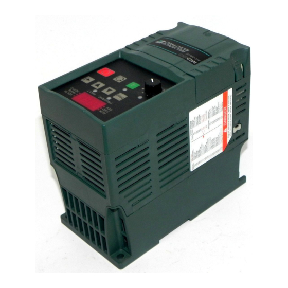
HAPTER About the MD60 Drive This chapter provides information about the MD60 AC drive, including: • How to identify the drive • Descriptions of NEMA ratings 2.1 Identifying the Drive by Model Number Each drive can be identified by its model number, as shown in figure 2.1. -
Page 14: Md60 Drive Ratings, Model Numbers, And Frame Sizes
2.2 MD60 Drive Ratings, Model Numbers, and Frame Sizes Similar MD60 drive sizes are grouped into frame sizes to simplify re-ordering and dimensioning. Refer to figure 3.2 for the dimensions of each frame size. Table 2.1 provides MD60 drive ratings, model numbers, and frame sizes. -
Page 15: Kits
2.3 Kits Table 2.2 lists kits for the MD60 drive. Contact Reliance Electric for more information about these kits. Table 2.2 – Standard Kits Kit Description Model Number MD60 Serial Converter and cables MDCOMM-232 VS Utilities Software CD RECOMM-VSUTIL MD60 Serial Converter (includes VS... -
Page 16: Storage Guidelines
Store the drive within an ambient temperature range of -40° to +85° C. • Store the drive within a relative humidity range of 0% to 95%, non-condensing. • Do not expose the drive to a corrosive atmosphere. MD60 AC Drive User Manual... -
Page 17: Chapter 3 Mounting The Drive
3.1 General Requirements for the Installation Site It is important to properly plan before installing an MD60 drive to ensure that the drive’s environment and operating conditions are satisfactory. The area behind the drive must be kept clear of all control and power wiring. -
Page 18: Operating Conditions
IP 20/Open Type Use Mounting Option B (122°F) (figure 3.1) Rating requires installation of the MD60 NEMA 1/IP30 Kit. 3.1.2 Recommended Mounting Clearances Refer to figure 3.1 for the minimum mounting clearances. Refer to section 3.1.3 for drive mounting dimensions. -
Page 19: Mounting Dimensions For The Md60 Drive
3.1.3 Mounting Dimensions for the MD60 Drive Overall dimensions and weights are illustrated in figures 3.2 and 3.3 as an aid to calculating the total area required by the MD60 drive. Dimensions are in millimeters and (inches). Weights are in kilograms and (pounds). -
Page 20: Mounting The Drive
3.2.1 Protecting the Drive from Debris A plastic top panel is included with the drive. Install the panel to prevent debris from falling through the vents of the drive housing during installation. Remove the panel for IP 20/Open Type applications. MD60 AC Drive User Manual... -
Page 21: Chapter 4 Grounding The Drive
HAPTER Grounding the Drive ATTENTION: The following information is merely a guide for proper installation. Rockwell Automation cannot assume responsibility for the compliance or the noncompliance to any code, national, local or otherwise for the proper installation of this drive or associated equipment. -
Page 22: Rfi Filter Grounding
Some local codes may require redundant ground connections. The integrity of all connections should be periodically checked. MD60 AC Drive User Manual... -
Page 23: Chapter 5 Installing Power Wiring
HAPTER Installing Power Wiring ATTENTION: The user is responsible for conforming with all applicable local and national codes. Failure to observe this precaution could result in damage to, or destruction of, the equipment. ATTENTION: To avoid a possible shock hazard caused by induced voltages, unused wires in the conduit must be grounded at both ends. -
Page 24: Verifying Drive Ac Input Ratings Match Available Power
Be sure input power to the drive corresponds to the drive nameplate voltage and frequency. 5.2.1 Ungrounded Distribution Systems ATTENTION: MD60 drives contain protective MOVs that are referenced to ground. These devices should be disconnected if the drive is installed on an ungrounded distribution system. -
Page 25: Figure 5.3 - Jumper Location (A Frame Shown)
Disconnecting MOVs To disconnect MOVs, you must remove the external jumper located on the lower left side of the front of the drive. To remove the jumper, use the following procedure and refer to figures 5.3 and 5.4. Step 1. Open the cover. -
Page 26: Input Power Conditioning
6000V (lightning) Phase-to-ground voltage exceeds 125% of • Remove MOV jumper to normal line-to-line voltage ground and install Ungrounded distribution system isolation transformer with grounded secondary, if necessary. Contact Reliance Electric for application and ordering information. MD60 AC Drive User Manual... -
Page 27: Power Wiring Specifications
5.3 Power Wiring Specifications Table 5.2 – Power Wiring Specifications Power Wire Rating Recommended Copper Wire Unshielded 600V, 75°C (167°F) 15 mils insulated, dry location THHN/THWN Shielded 600V, 90°C (194°F) Belden 29501-29507 or RHH/RHW-2 equivalent Shielded Tray rated 600V, 90°C (194°F) Shawflex 2ACD/3ACD or RHH/RHW-2 equivalent... -
Page 28: Fuses And Circuit Breakers
5.4. Fuses The MD60 drive has been UL tested and approved for use with input fuses. The ratings in table 5.4 are the minimum recommended values for use with each drive rating. The devices listed in this table are provided to serve as a guide. -
Page 29: Table 5.4 - Drive, Fuse, And Circuit Breaker Ratings
Circuit Breakers The “other devices” listings in table 5.4 include both circuit breakers (inverse time or instantaneous trip) and self-protecting motor starters. If one of these is chosen as the desired protection method, the following requirements apply. • IEC and UL – Both types of devices are acceptable for IEC and UL installations. -
Page 30: Table 5.5 - Shielded Motor Cable Types Acceptable For 200-600 Volt Installations
600V, 75°C or 90°C • Four tinned copper conductors with (Option 1) (167°F or 194°F) XLPE insulation RHH/RHW-2 • Foil shield and tinned copper drain Belden 29501- wire with 85% braid coverage 29507 or equivalent • PVC jacket MD60 AC Drive User Manual... -
Page 31: Reflected Wave Protection
Table 5.5 – Shielded Motor Cable Types Acceptable for 200-600 Volt Installations Location Rating/Type Description Standard Tray rated 600V, • Three tinned copper conductors with (Option 2) 75°C or 90°C (167°F XLPE insulation or 194°F) RHH/ • 5 mil single helical copper tape (25% RHW-2 overlap min.) with three bare copper Shawflex 2ACD/... -
Page 32: Output Disconnect
If it is necessary to disconnect power to the motor while the drive is providing output power, an auxiliary contact should be used to simultaneously disable drive control run commands. 5-10 MD60 AC Drive User Manual... -
Page 33: Chapter 6 Installing Control Wiring
Failure to observe this precaution could result in bodily injury. Depending upon the requirements of the application, the MD60 drive can be configured to provide either a coast-to-rest or a ramp- to-rest operational stop without physical separation of the power source from the motor. -
Page 34: Compliance With Machinery Safety Standard En 60204-1:1992
This section applies to you if you must comply with machinery safety standard EN 60204-1:1992, part 9.2.5.4, Emergency Stop. The MD60 drive coast-to-rest stop is a category 0 operational stop. The ramp-to-rest stop is a category 1 operational stop. You can also implement a category 2 stop with power maintained to the motor at zero speed. -
Page 35: I/O Wiring Recommendations
Important: I/O terminals labeled “Common” are not referenced to the safety ground (PE) terminal and are designed to greatly reduce common mode interference. ATTENTION: Driving the 4-20 mA analog input from a voltage source could cause component damage. Verify proper configuration prior to applying input signals. -
Page 36: Wiring The Control Terminal Block
RS485 port is used to connect the drive to a personal computer running VS Utilities via a Serial Converter module, and for connection to the Remote Nema 4x/12 or Copy Cat Keypads. Figure 6.1 – Wiring the Control Terminal Block MD60 AC Drive User Manual... -
Page 37: I/O Wiring Examples
6.4.1 I/O Wiring Examples Input/Output Connection Example Potentiometer P038 (Speed Reference) = 2 “0-10V Input” 1-10k Ohm Pot. Recommended (2 watt minimum) Analog Input Voltage Current 0 to +10V, 100k ohm P038 (Speed Reference) = 2 P038 (Speed Reference) = 3 impedance “0-10V Input”... - Page 38 A stop input to I/O Start Start Terminal 01 will stop the Direction drive as specified by P037 Direction (Stop Mode). I/O Terminal 03 +24V Common determines direction. Figure 6.2 – I/O Wiring Examples MD60 AC Drive User Manual...
-
Page 39: Typical Multiple Drive Connection Examples
Input/Output Connection Example 3 Wire SNK Control - Internal Supply (SNK) Reversing Stop Start Direction Figure 6.2 – I/O Wiring Examples 6.4.2 Typical Multiple Drive Connection Examples Table 6.3 – Typical Multiple Drive Connection Examples Input Connection Example Multiple Digital Input Connections Customer Inputs... -
Page 40: Start And Speed Reference Control
Start and direction commands come from P036 (Start Source). Run as specified by P038 (Speed Reference). Start and direction commands come from P036 (Start Source). Figure 6.3 – Override Priority for the Speed Reference Command MD60 AC Drive User Manual... -
Page 41: Accel/Decel Selection
6.6 Accel/Decel Selection The selection of Accel/Decel rates can be made through digital inputs, RS485 communications and/or parameters. See figure 6.4. Jog input A079 (Jog Accel/Decel) used. enabled and active: A051 or A052 = 2 Active when RS485 port A067 (Accel Time 2)/A068 (Decel Time 2) controls speed selected by RS485 port. - Page 42 6-10 MD60 AC Drive User Manual...
-
Page 43: Chapter 7 Completing The Installation
HAPTER Completing the Installation This chapter provides instructions on how to perform a final check of the installation before and after power is applied to the drive. ATTENTION: Only qualified electrical personnel familiar with the construction and operation of this equipment and the hazards involved should start and adjust it. -
Page 44: Powering Up After Installation Is Complete
To simplify drive setup, the most commonly programmed parameters are organized in the Basic parameter group. If a fault code appears on power up, refer to chapter 10, Troubleshooting the Drive, for an explanation of the fault code. MD60 AC Drive User Manual... -
Page 45: Using The Integral Keypad To Program And Control The Drive
This chapter provides an overview of the integrated keypad and how to use it to program and control the MD60 drive. Parameter descriptions are provided in chapter 9. 8.1 Keypad Components... -
Page 46: Display Description
Pot Status Steady Indicates potentiometer on Green integral keypad is active. Start Key Status Steady Indicates Start key on integral Green keypad is active. The Reverse key is also active unless disabled by A095 (Reverse Disable). MD60 AC Drive User Manual... -
Page 47: Key Descriptions
8.1.3 Key Descriptions Refer to figure 8.1 for the location of the keys described in table 8.2. Table 8.2 – Key Descriptions Name Description • Program Enter/exit program mode. PROG • Scroll through parameter groups. • Back up one step in programming menu. -
Page 48: About Parameters
The Basic Parameter Group, (Pnnn) contains the most commonly used parameters to simplify the start-up process. • The Advanced Parameter Group (Annn) contains parameters used for more advanced applications. • The Display Parameter Group (dnnn) contains parameters that indicate actual drive conditions. MD60 AC Drive User Manual... -
Page 49: Viewing And Adjusting Basic (P) And Advanced (A) Parameters
8.4 Viewing and Adjusting Basic (P) and Advanced (A) Parameters Use the following procedure to view and adjust the Basic and Advanced parameters. Table 8.3 – Viewing and Adjusting Basic (P) and Advanced (A) Parameters Procedure Sample Display VOLTS PROG AMPS Step 1. -
Page 50: Viewing The Display (D) Parameters
Display Group parameter list and scroll through the parameter list as described in step 2. Note that the last user-selected Display parameter is saved when power is removed and is displayed by default when power is re-applied. MD60 AC Drive User Manual... -
Page 51: Chapter 9 Parameter Descriptions
HAPTER Parameter Descriptions The following information is provided for each parameter along with its description: Parameter Number: Unique number assigned to each parameter. Parameter Name: Unique name assigned to each parameter. Range: Predefined parameter limits or selections. Note that a negative Hz value indicates reverse rotation. -
Page 52: Basic Program Group Parameters
Sets the lowest frequency the drive will output continuously. P035 Maximum Frequency Range: 0 to 240 Hz Default: 60 Hz See also: d001, d002, d013, P034, A078, A111, A113, A115 Sets the highest frequency the drive will output. MD60 AC Drive User Manual... - Page 53 P036 Start Source Range: 0 = Keypad 1 = 3-Wire 2 = 2-Wire 3 = 2-Wire Level-Sensitive 4 = 2-Wire High-Speed 5 = RS485 Port Default: 0 = Keypad See also: d012, P037 Sets the control scheme used to start the drive. Refer to section 6.6, Start and Speed Reference Control, for details about how other drive settings can override the setting of this parameter.
- Page 54 Once the stop input is inactive, the drive will restart. On firmware versions 1.05 and later, once a stop input is received, the start command must transition from high to low to high for the drive to start. MD60 AC Drive User Manual...
- Page 55 P037 Stop Mode Range: 0 = Ramp, Clear Fault 1 = Coast, Clear Fault 2 = DC Brake, Clear Fault 3 = DC Brake with Shutoff, Clear Fault 4 = Ramp 5 = Coast 6 = DC Brake 7 = DC Brake with Shutoff Default: 1 = Coast, Clear Fault See also:...
- Page 56 A070-A073 (Preset Frequency x) when A051 and A052 (Digital Inx Select) are programmed as “Preset Frequencies,” and the digital inputs are active. 5 = RS485 Port: External frequency command from the communications port. MD60 AC Drive User Manual...
-
Page 57: Figure 9.1 - Accel Time 1 (P039)
P039 Accel Time 1 Range: 0.1 to 600.0 sec Default: 5.0 sec See also: P038, P040, A051, A052, A067, A070-A073 Sets the rate of acceleration for all speed increases. See figure 9.1. Maximum Frequency / Accel Time = Accel Rate [Maximum Freq] Speed [Accel Time]... -
Page 58: Advanced Group Parameters
Preset Speed and is active. 5 = Local: When active, sets the integral keypad as the start source and the potentiometer on the integral keypad as the speed source. MD60 AC Drive User Manual... - Page 59 6 = RS485 Port: When active, sets communications device as default start/speed command source. 7 = Clear Fault: When active, clears an active fault and resets the drive. 8 = Ramp Stop, CF: Causes drive to immediately ramp to a stop regardless of how Stop Mode (P037) is set.
- Page 60 Relay Out Level (A056). 0=Off, 1=On. 21 = NonRec Fault: Value set in Auto Rstrt Tries (A092) is exceeded, is set to zero with drive defaulted, or a non-resettable fault occurs. 9-10 MD60 AC Drive User Manual...
-
Page 61: Figure 9.3 - Accel Time 2 (A067)
A056 Relay Output Level Range: 0.0 to 9999 (see table 9.1) Default: See also: A055 Sets the trip point for the output relay if the value of Relay Output Select (A055) is 6, 7, 8, 10 or 20. See table 9.1. Table 9.1 –... -
Page 62: Figure 9.4 - Decel Time 2 (A068)
Provides the frequency command to the drive when Speed Reference (P038) is set to 1 (Internal Frequency). When enabled, this parameter will change the frequency command in “real time” using the integral keypad keys when in program mode. 9-12 MD60 AC Drive User Manual... -
Page 63: Table 9.2 - Selecting The Reference Source Using Presets
A070 Preset Frequency 0 A071 Preset Frequency 1 A072 Preset Frequency 2 A073 Preset Frequency 3 Range: 0.0 to 240.0 Hz Default: See also: P038, A051, A052 To activate Preset Frequency 0, set P038 (Speed Reference) to option 4 (Preset Frequency 0-3). Provides a fixed frequency command value when Digital Inx Select (A051, A052) is set to option 4 (Preset 1 &... -
Page 64: Figure 9.5 - Dc Brake Level (A081)
Ramp-to-Stop Mode DC Injection Braking Mode Voltage [DC Brake Time] Speed [DC Brake Time] [DC Brake Level] [DC Brake Level] Time Time Stop Command Stop Command Figure 9.5 – DC Brake Level (A081) 9-14 MD60 AC Drive User Manual... -
Page 65: Figure 9.6 - S Curve% (A083) Examples
A082 DB Resistor Select Range: 0 = Disabled 1 = Reliance Electric Standard Resistor (5% Duty Cycle) 2 = No Protection (100% Duty Cycle) 3 to 99 = Duty Cycle Limited (3% to 99% Duty Cycle) Default: 0 = Disabled See also: Enables/disables external dynamic braking. -
Page 66: Figure 9.7 - Start Boost (A084)
Volts per Hz curve. Note that the drive may add additional voltage unless option 5 is selected. See figure 9.7. 1/2 Base Volts Settings 5-14 % [Motor NP Hertz] Figure 9.7 – Start Boost (A084) 9-16 MD60 AC Drive User Manual... -
Page 67: Figure 9.8 - Motor Ol Select (A090)
A088 Maximum Voltage Range: 20 to Drive Rated Volts Default: Drive Rated Volts See also: Sets the highest voltage the drive will output. A089 Current Limit Range: 0.1 to (Drive Rated Amps x 1.8) Default: Drive Rated Amps x 1.8 See also: Maximum output current allowed before current limiting occurs. -
Page 68: Figure 9.9 - Derating Guidelines Based On Pwm Frequency (A091) Selection
ATTENTION: Equipment damage and/or personal injury may result if this parameter is used in an inappropriate application. Do not use this function without considering applicable local, national, and international codes, standards, regulations, or industry guidelines. 9-18 MD60 AC Drive User Manual... - Page 69 A093 Auto Restart Delay Range: 0.0 to 120.0 sec Default: 1.0 sec See also: A092 Sets the time between restart attempts when Auto Restart Tries (A092) is set to a value other than zero. Refer to section 10.1.2 for more information on the Auto Restart/Run feature. A094 Start At Power Up Range: 0 = Disabled...
- Page 70 This setting attempts to correct this condition. Mechanical = Some drive/motor combinations have mechanical resonances which can be excited by the drive current regulator. This setting slows down the current regulator response and attempts to correct this condition. 9-20 MD60 AC Drive User Manual...
- Page 71 A098 SW Current Trip Range: 0.0 to (Drive Rated Amps x 2) Default: 0.0 (Disabled) See also: Enables/disables a software instantaneous (within 100 ms) current trip. A099 Process Factor (Display Scaling) Range: 0.1 to 999.9 Default: 30.0 See also: d010 Scales the value displayed by Process Display (d010).
- Page 72 A102 Testpoint Select Range: 0400 to FFFF Default: 0400 See also: d019 Used by Rockwell Automation field service personnel. A103 Comm Data Rate Range: 0 = 1200 1 = 2400 2 = 4800 3 = 9600 4 = 19.2 K 5 = 38.4 K...
- Page 73 0 = Fault (Default): Drive will fault on an F81 Comm Loss and coast to stop. 1 = Coast to Stop: Stops the drive via coast to stop. 2 = Stop: Stops the drive via the setting in Stop Mode (P037). 3 = Continue Last Speed: Drive continues operating at communication commanded speed saved in RAM.
- Page 74 Use parameter d020 (0 - 10 V Analog Input) to verify the analog input signal. Setting this parameter to a value less than 0 - 10 V Analog Input Low (A110) inverts the analog signal. 9-24 MD60 AC Drive User Manual...
- Page 75 A112 4 - 20 mA Analog Input Low Range: 0.0 to 100.0% Default: 0.0% See also: 113, d021 Parameters A112 and A113 enable scaling of the 4 - 20 mA analog input. The drive reaches minimum frequency at the current setting in parameter A112.
- Page 76 Default: 0.00 See also: Scales the time value when the drive is running at Maximum Freq. (P035). When set to a value other than zero, Process Display (D010) indicates the duration of the process. 9-26 MD60 AC Drive User Manual...
-
Page 77: Display Group Parameters
9.3 Display Group Parameters d001 Output Frequency Range: 0.0 to Maximum Frequency Default: Read Only See also: d002, d010, P034, P035 The output frequency present at terminals T1, T2, and T3 (U, V, and d002 Commanded Frequency Range: 0.0 to Maximum Frequency Default: Read Only See also:... -
Page 78: Figure 9.10 - Drive Status (D006) Bit Definitions
(that is, Fault 1 Code in d007 will contain the more recent fault). Repetitive faults will be recorded only once. Refer to chapter 10 for the fault code descriptions. 9-28 MD60 AC Drive User Manual... -
Page 79: Figure 9.11 - Control Source (D012) Bit Definitions
d010 Process Display Range: 0.00 to 99999 Default: Read Only See also: d001, A099 The output frequency scaled by A099 (Process Factor). Output Frequency x Process Factor = Process Display d012 Control Source Range: 0 to 9 See figure 9.11. Default: Read Only See also:... -
Page 80: Figure 9.12 - Control Input Status (D013) Bit Definitions
The status of the control terminal block digital inputs. Digital In1 Sel (I/O Terminal 05) Digit 0 Digital In2 Sel (I/O Terminal 06) Digit 1 Reserved Digit 2 Reserved Digit 3 Figure 9.13 – Digital Input Status (d014) Bit Definitions 9-30 MD60 AC Drive User Manual... -
Page 81: Figure 9.14 - Comm Status (D015) Bit Definitions
The Main Control Board software version. d017 Drive Type Range: 1001 to 9999 Default: Read Only See also: Used by Rockwell Automation field service personnel. d018 Elapsed Run Time Range: 0 to 9999 Hours Default: Read Only See also: The accumulated time drive is outputting power. The time is displayed in 10-hour increments (that is, 1 = 10 hours). - Page 82 The value present at the drive’s 4 - 20 mA analog input. d024 Drive Temp Range: 0 to 120 Default: Read Only See also: Displays the present operating temperature of the drive power section. 9-32 MD60 AC Drive User Manual...
-
Page 83: Chapter 10 Troubleshooting The Drive
Failure to observe this precaution could result in severe bodily injury or loss of life. The MD60 constantly monitors its status and provides the following ways to determine the status of the drive and to troubleshoot problems that may occur: •... -
Page 84: Manually Clearing Faults
To automatically clear an OverVoltage, UnderVoltage, or Heatsink OverTemp fault without restarting the drive: Step 1. Set A092 (Auto Restart Tries) to a value other than 0. Step 2. Set A093 (Auto Restart Delay) to 0. 10-2 MD60 AC Drive User Manual... -
Page 85: Table 10.1 - Fault Descriptions And Corrective Actions
Use caution when enabling this feature since the drive will attempt to issue its own start command based on user-selected programming. Table 10.1 – Fault Descriptions and Corrective Actions Fault Description Action • Auxiliary Y Auxiliary input interlock Check remote wiring. Input is open. - Page 86 Check the motor and Short been detected drive output terminal between these two Phase UW wiring for a shorted output terminals. Short condition. Phase VW • Replace drive if fault Short cannot be cleared. 10-4 MD60 AC Drive User Manual...
- Page 87 Table 10.1 – Fault Descriptions and Corrective Actions (Continued) Fault Description Action • Params N The drive was Clear the fault or cycle Defaulted commanded to write power to the drive. default values to • Program the drive EEPROM. parameters as needed. Y Programmed A098 Check load requirements OverCurrent...
-
Page 88: Troubleshooting Tables
Wire inputs correctly and/or figure 6.2 for wiring install jumper. examples. • 2-wire control requires Run Forward, Run Reverse or Jog input. • 3-wire control requires Start and Stop inputs • Stop input is always required. 10-6 MD60 AC Drive User Manual... -
Page 89: Problem: Drive Does Not Start From Integral Keypad
10.2.2 Problem: Drive Does Not Start From Integral Keypad Table 10.3 – Problem: Drive Does Not Start From Integral Keypad Cause(s) Indication Corrective Action Integral keypad is not Start Key • Set parameter P036 enabled. Status LED is (Start Source) to option 0 not on. -
Page 90: Problem: Motor And/Or Drive Will Not Accelerate To Commanded Speed
Cause(s) Indication Corrective Action Motor data was incorrectly None 1. Correctly enter motor entered. nameplate data into P031, P032 and P033. 2. Enable A097 (Compensation). 3. Use A084 (Start Boost) to reduce boost level. 10-8 MD60 AC Drive User Manual... -
Page 91: Problem: Drive Will Not Reverse Motor
10.2.6 Problem: Drive Will Not Reverse Motor Direction. Table 10.7 – Problem: Drive Will Not Reverse Motor Direction Cause(s) Indication Corrective Action Digital input is not selected None Check (Digital Inx Select). for reversing control. Choose correct input and program for reversing mode. Digital input is incorrectly None Check input wiring. - Page 92 10-10 MD60 AC Drive User Manual...
-
Page 93: Appendix A Technical Specifications
PPENDIX Technical Specifications Environment Altitude: 1000 m (3300 ft) maximum without derating Ambient Operating IP 20: -10° C (14° F) to 50° C (122° F) Temperature NEMA 1/IP30: -10° C (14° F) to 40° C (104° F) Without Derating: Storage -40°... - Page 94 • 200-240 V AC Input – Trip occurs at 405 V DC bus voltage (equivalent to 290 V AC incoming line) • 380-460 V AC Input – Trip occurs at 810 V DC bus voltage (equivalent to 575 V AC incoming line) MD60 AC Drive User Manual...
- Page 95 Under Voltage: • 100-120 V AC Input – Trip occurs at 210 V DC bus voltage (equivalent to 75 V AC incoming line) • 200-240 V AC Input – Trip occurs at 210 V DC bus voltage (equivalent to 150 V AC incoming line •...
- Page 96 MD60 AC Drive User Manual...
-
Page 97: Appendix B Record Of User Settings
PPENDIX Record of User Settings B.1 Basic Parameter Group Default Page Parameter Name Value User Setting P031 Motor NP Volts Varies P032 Motor NP Hertz 60 Hz P033 Motor OL Current Varies P034 Minimum Frequency 0 Hz P035 Maximum Frequency 60 Hz P036 Start Source 0 = Keypad... - Page 98 A095 Reverse Disable 0 = Reverse 9-19 Enabled A096 Flying Start Enable 0 = Disabled 9-20 A097 Compensation 1 = Electrical 9-20 A098 SW Current Trip 0.0 (Disabled) 9-21 A099 Process Factor 30.0 9-21 (Display Scaling) MD60 AC Drive User Manual...
- Page 99 Default Page Parameter Name Value User Setting A100 Fault Clear 0 = Ready 9-21 A101 Program Lock 0 = Unlocked 9-21 A102 Testpoint Select 0000 9-22 A103 Comm Data Rate 4 = 19.2 K 9-22 A104 Comm Node Address 9-22 A105 Comm Loss Action 0 = Fault 9-22...
- Page 100 MD60 AC Drive User Manual...
- Page 101 PPENDIX Parameters Cross-Referenced by Name Parameter Default Page Parameter Name Group Value 0 - 10 V Analog Input d020 Display Read Only 9-32 0 - 10 V Analog Input A111 Advanced 100.0% 9-24 High 0 - 10 V Analog Input A110 Advanced 0.0% 9-24...
- Page 102 Display Read Only 9-27 Output Voltage d004 Display Read Only 9-27 Preset Frequency 0 A070 Advanced 0.0 Hz 9-13 Preset Frequency 2 A072 Advanced 0.0 Hz 9-13 Preset Frequency 3 A073 Advanced 0.0 Hz 9-13 MD60 AC Drive User Manual...
- Page 103 Parameter Default Page Parameter Name Group Value Preset Frequency 1 A071 Advanced 0.0 Hz 9-13 Process Display d010 Display Read Only 9-29 Process Factor A099 Advanced 30.0 9-21 Process Time Lo A115 Advanced 0.00 9-26 Process Time Hi A116 Advanced 0.00 9-26 Program Lock...
- Page 104 MD60 AC Drive User Manual...
- Page 105 Conformity with the Low Voltage (LV) Directive and Electromagnetic Compatibility (EMC) Directive has been demonstrated using harmonized European Norm (EN) standards published in the Official Journal of the European Communities. The MD60 AC drive complies with the EN standards listed below when installed according to the User Manual.
- Page 106 Essential Requirements for CE Compliance The following conditions must be satisfied for MD60 drives to meet the requirements of EN61800-3. • Grounding as described in figure D.1. Refer to chapter for additional grounding recommendations. • Output power, control (I/O) and signal wiring must be braided, shielded cable with a coverage of 75% or better, metal conduit or equivalent attenuation.
- Page 107 Shielded Enclosure (1) IP 30/NEMA 1/UL Type 1 NEMA 1/IP30 Kit Option Kit EMI Fittings and Metal Conduit EMI Filter R/L1 U/T1 S/L2 V/T2 T/L3 W/T3 Enclosure Ground Connection Shielded Motor Cable Building Structure Steel (1) First Environment Unrestricted Distribution installations require a shielded enclosure.
- Page 108 MD60 AC Drive User Manual...
- Page 109 PPENDIX Accessories E.1 Dynamic Brake Modules Table E.1 – Dynamic Brake Modules Drive Ratings Minimum Resistance Input Voltage (ohms) Model Number 120V 50/60 Hz 0.25 AK-R2-091P500 1-Phase 0.75 AK-R2-091P500 0.75 AK-R2-091P500 AK-R2-091P500 240V 50/60 Hz 0.25 AK-R2-091P500 1-Phase AK-R2-091P500 0.75 AK-R2-091P500 AK-R2-091P500 240V 50/60 Hz...
- Page 110 Frame A Frame B 30.0 61.0 (1.18) (2.40) 60.0 17.0 31.0 59.0 (0.67) (2.36) (1.22) (2.32) 316.0 335.0 386.0 405.0 (12.44) (13.19) (15.20) (15.94) SURFACES MAY BE 13.0 (0.51) Frame Model Number AK-R2-091P500, AK-R2-047P500, AK-R2-360P500 AK-R2-030P1K2, AK-R2-120P1K2 Figure E.1 – Dynamic Brake Modules: Dimensions MD65 AC Drive User Manual...
- Page 111 E.2 EMC Line Filters Table E.2 – EMC Line Filters Drive Ratings S Type Filter L Type Filter Input Voltage Model Number Model Number 120V 50/60 Hz 0.25 – 6MDF-010AL 1-Phase – 6MDF-010AL 0.75 – 6MDF-018BL – 6MDF-025CL 240V 50/60 Hz 0.25 6MDF-010AL 1-Phase...
- Page 112 (1.97) (3.15) 29.8 (2.36) (1.17) (8.19) (8.66) (8.19) 17.8 5.5 (0.22) (0.70) (0.94) Dimensions are in mm and (in). Model Numbers: 6MDF-9P5AS, -AL; 6MDF-5P7AS, -AL; Figure E.2 – Frame A EMC Line Filters: Dimensions MD65 AC Drive User Manual...
- Page 113 (1.97) (3.94) 29.8 (3.07) (1.17) (8.54) (9.02) (8.50) 17.8 5.5 (0.22) (0.70) 24.0 (0.94) Dimensions are in mm and (in). Model Numbers: 6MDF-012BS, -BL; 6MDF-021BS, -BL; 6MDF-018BS, -BL Figure E.3 – Frame B EMC Line Filters: Dimensions Accessories...
- Page 114 CopyCat capable, IP30 (NEMA Type 1); includes 1.0 meter cable; panel-mount with optional Bezel Kit) Bezel Kit (panel mount for Remote Handheld OIM) MDBZL-N1 OIM Cable (1.0 meter OIM-to-RJ45 cable) MDCBL-CC1 OIM Cable (2.9 meter OIM-to-RJ45 cable) MDCBL-CC3 MD60 AC Drive User Manual...
- Page 115 25,0 93,0 (0.98) (3.66) (in.) 180,0 (7.08) 2.0m 67,0 (2.63) 60,0 (2.36) 77,0 (3.03) ∅19,1 (0.75) 53,5 (2.11) 77,0 (3.03) ∅4,8 (0.19) Dimensions are in mm and (in). Figure E.4 – Remote OIM (M/N MD4ALCD) Accessories...
- Page 116 11.1 (0.44) (3.66) 25.2 (0.99) (7.09) (2.64) (2.36) (6.06) (0.19) (3.03) 19.1 (0.75) 23.5 (0.93) Dimensions in mm and (in). Figure E.5 – NEMA Type 1 Bezel (M/N MDBZL-N1): Dimensions MD60 AC Drive User Manual...
- Page 117 Figure F.2 – Network Wiring Diagram Only pins 4 and 5 on the RJ45 plug should be wired. The other pins on the MD60 RJ45 socket contain power, etc., for other Rockwell Automation peripheral devices and must not be connected.
-
Page 118: Parameters
32 nodes are needed on the network. Control Terminal 16 on the MD60 must also be connected to PE ground (there are two PE terminals on the drive). -
Page 119: Command
Supported Modbus Function Codes The peripheral interface (MDI) used on MD60 drives supports some of the Modbus function codes. Table F.2 – Supported Modbus Function Codes Modbus Function Code Command Read Holding Registers Preset (Write) Single Register Important: Modbus devices can be 0-based (registers are numbered starting at 0) or 1-based (registers are numbered starting at 1). - Page 120 Writing (06) Logic Command Data The MD60 drive can be controlled via the network by sending Function Code 06 writes to register address 8192 (Logic Command). P036 (Start Source) must be set to 5 “RS485 (MDI) Port” in order to accept the commands.
- Page 121 Writing (06) Reference The Speed Reference to a MD60 drive can be controlled via the network by sending Function Code 06 writes to register address 8193 (Reference). P038 (Speed Reference) must be set to 5 “RS485 (MDI) Port” in order to accept the Speed Reference.
- Page 122 Reading (03) Feedback The Feedback (Output Frequency) from the MD60 drive can be read via the network by sending Function Code 03 reads to register address 8451 (Feedback). Table F.6 – Feedback Feedback Address (Decimal) Description A xxx.x decimal value where the decimal point is fixed. For 8451 example, a decimal “123”...
- Page 123 Reading (03) Drive Error Codes The MD60 Error Code data can be read via the network by sending Function Code 03 reads to register address 8449 (Drive Error Codes). Table F.7 – Error Codes Logic Status Address Value (Decimal) (Decimal)
- Page 124 To access drive parameters, the Modbus register address equals the parameter number. For example, a decimal “1” is used to address parameter d001 (Output Freq) and decimal “39” is used to address parameter P039 (Accel Time 1). MD60 AC Drive User Manual...
- Page 125 PPENDIX RJ45 Splitter Cable The MD60 drive provides a RJ45 port to allow the connection of a single peripheral device. The RJ45 Splitter Cable can be used to connect a second MDI peripheral device to the drive. Connectivity Guidelines ATTENTION: The peripherals may not perform as intended if these Connectivity Guidelines are not followed.
- Page 126 Figure G.1 – RJ45 Splitter Cable (M/N AK-U0-RJ45-SCI) (PIN 5) PIN 8 (PIN 4) PIN 1 Figure G.2 – RJ45 Two-Position Terminal Block Module M/N AK-U0-RJ45-TB2P PIN 8 PIN 1 Figure G.3 – RJ45 Module With Integrated Termination Resistor (M/N AK-U0-RJ45-TR1) MD60 AC Drive User Manual...
- Page 127 Connecting One Temporary Peripheral MD60 Drive MD60 Serial Converter Handheld OIM Parameter 1 (Module Cfg) set to "Auto" (default) or "Master" and connected to Master port (M) on RJ45 Splitter Cable Parameter 9 (Device Type) set to "Auto" (default) or "Master" and connected to Master port (M) on RJ45 Splitter Cable Figure G.4 –...
- Page 128 4 and 5 only. Both the Master (M) and Slave (S) ports on the RJ45 Splitter Cable operate as standard RS-485 ports in this configuration. Figure G.7 – Connecting an RS485 Network MD60 AC Drive User Manual...
- Page 129 NDEX Numerics recommendations Control Input Status (d013) 9-30 0 - 10 V Analog Input (d020) 9-32 Control Source (d012) 9-29 0 - 10 V Analog Input High (A111) 9-24 Control SW Version (d016) 9-31 0 - 10 V Analog Input Low (A110) 9-24 control terminal block 4 - 20 mA Analog Input High...
- Page 130 Motor OL Select (A090) 9-17 fuses Motor Overload fault 10-3 Motor Stalled fault 10-3 motor start/stop precautions mounting clearances Ground Fault 10-4 mounting specifications ground fault monitoring mounting the drive grounding the drive MOVs Index-2 MD60 AC Drive User Manual...
- Page 131 RWR (Reflective Wave Reducer) P parameters Parameter Checksum fault 10-5 parameters S Curve % (A083) 9-15 9-26 safety ground about Serial Converter, MD60 Advanced 9-26 shield termination Basic shielded motor cable cross-referenced by name Slip Compensation (A114) 9-25 specifications, technical...
- Page 132 UnderVoltage fault 10-3 weight, drive ungrounded distribution systems wiring unshielded power cables I/O examples wiring specifications control and signal power Index-4 MD60 AC Drive User Manual...
- Page 133 After you have completed this form, please return it to: Reliance Electric Standard Drives - Technical Documentation 6040 Ponders Court Greenville, SC 29617 Fax: 864-284-5483 Publication Name: MD60 AC Drive User Manual Publication Number: D2-3499-3 Publication Date: September 2003 Comments: Your Name: Date:...
- Page 136 2003 Rockwell International Corporation. All rights reserved. Publication D2-3499-3 - September 2003...
Need help?
Do you have a question about the MD60 and is the answer not in the manual?
Questions and answers