Table of Contents
Advertisement
Quick Links
This manual links to Armor PowerFlex AC Drive Fault Codes Reference Data,
publication
Reference Data, publication 35-RD001; download the spreadsheet now for offline
access.
Armor PowerFlex AC Drives
Bulletins 35E, 35S
User Manual
35-RD002
and to Armor PowerFlex AC Drive CIP Objects and Attributes
Original Instructions
Advertisement
Table of Contents

Subscribe to Our Youtube Channel
Related Manuals for Rockwell Automation Allen-Bradley 35E


Summary of Contents for Rockwell Automation Allen-Bradley 35E
- Page 1 This manual links to Armor PowerFlex AC Drive Fault Codes Reference Data, publication 35-RD002 and to Armor PowerFlex AC Drive CIP Objects and Attributes Reference Data, publication 35-RD001; download the spreadsheet now for offline access. Armor PowerFlex AC Drives Bulletins 35E, 35S User Manual Original Instructions...
- Page 2 Identifies information that is useful and can help to make a process easier to do or easier to understand. Rockwell Automation recognizes that some of the terms that are currently used in our industry and in this publication are not in alignment with the movement toward inclusive language in technology.
-
Page 3: Table Of Contents
Typical Configurations ......... . 28 Rockwell Automation Publication 35-UM001A-EN-P - May 2022... - Page 4 Set the IP Address..........61 Set the IP Address using Rotary Switches ..... . 61 Rockwell Automation Publication 35-UM001A-EN-P - May 2022...
- Page 5 Hardwired STO Operation ........91 Rockwell Automation Publication 35-UM001A-EN-P - May 2022...
- Page 6 Drive Safety Instruction Example ......115 Safety Feedback Interface (SFX) Instruction Operation ..115 Rockwell Automation Publication 35-UM001A-EN-P - May 2022...
- Page 7 Replacing an Armor PowerFlex Drive on a Safety Network ..139 Replace an Armor PowerFlex drive in a GuardLogix System..139 Rockwell Automation Publication 35-UM001A-EN-P - May 2022...
- Page 8 Configure Safety Actions ........181 Rockwell Automation Publication 35-UM001A-EN-P - May 2022...
- Page 9 Example: Read SS1 Fault Type....... . 221 Rockwell Automation Publication 35-UM001A-EN-P - May 2022...
- Page 10 Index ............223 Rockwell Automation Publication 35-UM001A-EN-P - May 2022...
-
Page 11: Preface
Armor PowerFlex drive. Rockwell Automation recognizes that some of the terms that are currently used in our industry and in this publication are not in alignment with the movement toward inclusive language in technology. We are proactively collaborating with industry peers to find alternatives to such terms and making changes to our products and content. - Page 12 Safe Torque Off emergency while the drive remains connected to the power supply. When STO is activated, the torque power cannot reach the drive, which stops and helps prevent any motor shaft rotation. Rockwell Automation Publication 35-UM001A-EN-P - May 2022...
-
Page 13: Additional Resources
Ethernet Reference Manual publication, ENET-RM002 Describes basic Ethernet concepts, infrastructure components, and infrastructure features. CIP Security with Rockwell Automation Products Application Technique, Provides information on CIP Security™, including which Rockwell Automation products publication SECURE-AT001 support CIP Security. Provides guidance on how to conduct security assessments, implement Rockwell System Security Design Guidelines Reference Manual publication, Automation®... -
Page 14: Ce Conformity
Description Industrial Automation Wiring and Grounding Guidelines, publication 1770-4.1 Provides general guidelines for installing a Rockwell Automation industrial system. Designed to harmonize with NEMA Standards Publication No. ICS 1.1-1987 and provides Safety Guidelines for the Application, Installation, and Maintenance of... -
Page 15: Armor Powerflex Variable Frequency Drives Overview
Bulletin Inputs and Outputs and Outputs Armor PowerFlex with integrated safety on EtherNet/ 1 bipolar safety output 4 inputs IP network 4 safety inputs 2 configurable I/Os Armor PowerFlex on EtherNet/IP network — Rockwell Automation Publication 35-UM001A-EN-P - May 2022... -
Page 16: Frame Size
In hardwired mode, Safe Torque Off (STO) can be used. Integrated safety supports Safe Torque Off (STO), integrated drive-based Safe Stop functions and integrated controller-based Safe Monitor functions. See Chapter 6, for details. Rockwell Automation Publication 35-UM001A-EN-P - May 2022... -
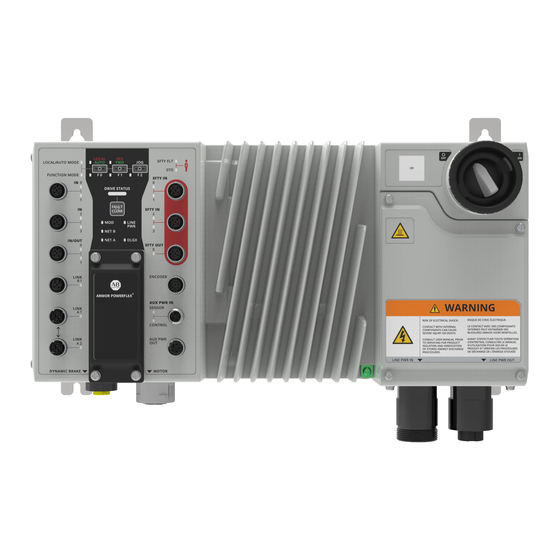
Page 17: Location Of Features
Dynamic Brake Connection Power IN Dynamic Brake Connection 3-phase Power OUT 24V DC Auxiliary Power OUT 3-phase Power IN 3-phase Power OUT 3-phase Power IN Motor and Electromechanical Brake Connection Motor and Electromechanical Brake Connection Rockwell Automation Publication 35-UM001A-EN-P - May 2022... -
Page 18: Catalog Number Explanation
Studio 5000 Logix Designer® application is the single software that is used for setup and commissioning. It’s accomplished through the installation and use of an Add-on Profile (AOP) downloaded from Product Compatibility and Download Center (PCDC). See page 11 for more information. Rockwell Automation Publication 35-UM001A-EN-P - May 2022... -
Page 19: Motor Control
Operation in this mode, creates a fixed relationship between output voltage and output frequency. Voltage is applied to the motor, which is based on the operating frequency command at a fixed volts/Hertz ratio. The ratio is calculated from the motor nameplate data. Rockwell Automation Publication 35-UM001A-EN-P - May 2022... -
Page 20: Sensorless Vector
This is shown in the curve in Figure 4 which represents 0%, 25%, 50%, and 100% S Curve. Note that half of the “S” is added to the beginning and half is added to the end of the ramp. Rockwell Automation Publication 35-UM001A-EN-P - May 2022... -
Page 21: Flying Start
You can configure the power level as an absolute amount of output current being supplied to the motor. You can also configure a monitor time, which delays the reporting of a load monitoring condition when the power is above or below the level. Rockwell Automation Publication 35-UM001A-EN-P - May 2022... -
Page 22: Motor Thermal Overload
Velocity skip bands can also be used to keep a machine from operating at a speed where operation is unstable or untested. Figure 5 - Velocity Skip Bands Frequency Command Frequency Drive Output Frequency 2x Skip Skip Frequency Frequency Band Time Rockwell Automation Publication 35-UM001A-EN-P - May 2022... -
Page 23: Fault Auto Reset
Torque is permitted when one input pair on one of the two safety input connectors is energized and disabled when either input is de-energized. Choose the desired safety input connector for hardwired Safe Torque Off Rockwell Automation Publication 35-UM001A-EN-P - May 2022... -
Page 24: Integrated Safety Functions
(5V or 12V) for the connected encoder. See Remove Front Logic Cover on page 62 for information on how to gain access to the encoder voltage supply switch. SWITCH Rockwell Automation Publication 35-UM001A-EN-P - May 2022... -
Page 25: Group Motor Application
Wye AC supply distribution and must be bonded to the power distribution ground. The shielded motor cable is ordered separately. Use the Rockwell Automation® power media and cable assemblies that are specified by the selection guide or instructions for the controller, to comply with the UL Listing of the controller. -
Page 26: Dynamic Brake Resistor
The Armor PowerFlex drive offers several methods to connect 3-phase power to the unit. You can select one of the three offered connectivity options via the catalog number configuration. Conduit/cord allows you to apply conduit or cord to manually terminate each conductor. Rockwell Automation Publication 35-UM001A-EN-P - May 2022... -
Page 27: Factory-Installed Options
The brake and motor conductors are integrated into a single cable assembly and ordered separately. Use the Rockwell Automation power media and cable assemblies that are specified by the selection guide or instructions for the drive, to comply with the UL Listing of the drive. -
Page 28: Typical Configurations
Armor PowerFlex Drive (35E) Protection 24V DC Power Supply Input - 0,1 Input - 0,1 Input - 2,3 Input - 2,3 Configurable I/O - 0,1 Configurable I/O - 0,1 24V DC Ethernet cable Encoder 3-phase Power Rockwell Automation Publication 35-UM001A-EN-P - May 2022... -
Page 29: Safety Drives Configuration
Input - 0,1 Input - 0,1 Safety Device Feedback Input - 2,3 Input - 2,3 Safety Device Feedback Configurable I/O - 0,1 Configurable I/O - 0,1 24V DC Auxiliary/Control Power Ethernet cable Encoder 3-phase Power Rockwell Automation Publication 35-UM001A-EN-P - May 2022... -
Page 30: Integrated Sto
Input - 0,1 Input - 0,1 Safety Inputs Input - 2,3 Input - 2,3 Configurable I/O - 0,1 Configurable I/O - 0,1 Safety Bipolar Output 24V DC Auxiliary/Control Power Ethernet cable Encoder Encoder 3-phase Power Rockwell Automation Publication 35-UM001A-EN-P - May 2022... -
Page 31: Integrated Safe Speed Monitoring
Safety Bipolar Output Safety Bipolar Output 24V DC Auxiliary/Control Power Ethernet cable Encoder Encoder STO or timed SS1 Safety encoder performance feedback is required for SS1, SLS, SDI, and SLP performance 3-phase Power Rockwell Automation Publication 35-UM001A-EN-P - May 2022... - Page 32 Chapter 1 Armor PowerFlex Variable Frequency Drives Overview Notes: Rockwell Automation Publication 35-UM001A-EN-P - May 2022...
-
Page 33: Install The Armor Powerflex Drive
• Store within a relative humidity range of 5…95%, noncondensing. • Do not store equipment where it can be exposed to a corrosive atmosphere. • Do not store equipment in a construction area. Rockwell Automation Publication 35-UM001A-EN-P - May 2022... -
Page 34: Personal And Electrical Safety Precautions
ATTENTION: The National Electrical Code® (NEC®), NFPA®79, and any other governing regional or local code overrules the information in this manual. Rockwell Automation cannot assume responsibility for the compliance or proper installation of the Armor PowerFlex drive or associated equipment. A hazard of personal injury and/or equipment damage exists if codes are ignored during installation. -
Page 35: Precautions For Cold Temperature Conditions
Component damage can result if ESD control procedures are not followed. If you are not familiar with static control procedures, see an applicable ESD protection handbook. Rockwell Automation Publication 35-UM001A-EN-P - May 2022... -
Page 36: Environmental Considerations
90° rotation (with local disconnect pointing up) • 180° rotation (with high-voltage connectors pointing up) These deviations from the standard orientation may result in thermal or power derating. For additional details, see Configure Motor Protection on page 154. Rockwell Automation Publication 35-UM001A-EN-P - May 2022... - Page 37 180° Rotation Mount Front Back 90° Rotation Mount Back Front Up to 60° Tilt Mount 60° 60° ATTENTION: For proper heat dissipation and product operation, mount in one of the orientations shown in Figure Rockwell Automation Publication 35-UM001A-EN-P - May 2022...
-
Page 38: Armor Powerflex Drive Dimensions
406 (15.98) 143.8 (5.66) 365 (14.37) (9.76) (8.94) (7.99) (0.26) (2.8) (2.17) 23.3 29.5 (0.92) (1.16) 68.3 (2.69) 75.5 (2.97) 441 (17.36) 425 (14.37) 406 (15.98) (7.99) (6.38) (0.26) Alternate mounting bracket orientation Rockwell Automation Publication 35-UM001A-EN-P - May 2022... - Page 39 All dimensions are subject to change. Figure 12 - Armor PowerFlex Frame Size A: 180° Mount Position 406 (15.98) 365 (14.37) (7.99) (8.94) (9.76) (0.26) 143.8 (5.66) (2.8) (2.17) 23.3 29.5 (0.92) (1.16) 68.3 (2.69) 75.5 (2.97) Rockwell Automation Publication 35-UM001A-EN-P - May 2022...
- Page 40 Figure 13 - Armor PowerFlex Frame Size A: 90° Mount Position 143.8 (5.66) 203 (7.99) 162 (6.38) 71 (2.8) 58.3 (2.29) 103.3 (4.06) (17.76) (16.93) (15.98) 105.5 (4.15) 59.5 (2.34) 55 (2.17) (0.26) Rockwell Automation Publication 35-UM001A-EN-P - May 2022...
-
Page 41: Wiring And Workmanship Guidelines
The motor cable must be kept as short as possible to avoid electromagnetic emissions and capacitive currents. CE conformity of Armor PowerFlex drive with EMC Directive does not confirm that the entire machine installation complies with CE EMC requirements. Rockwell Automation Publication 35-UM001A-EN-P - May 2022... -
Page 42: Wiring
EMI filter to be damaged. The installer can connect the product ground in two different ways. The first method is to use the conduit/cord gland plate or the factory installed quick connect power connectors. Rockwell Automation Publication 35-UM001A-EN-P - May 2022... -
Page 43: Shielding And Grounding Of Motors And Motor Cables
3. The amount of cable-charging current available from the drive 4. Possible voltage drop (and subsequent loss of torque) for long wire runs Keep the motor cable lengths less than 14 m (45.9 ft) unless otherwise noted in the device specifications. Rockwell Automation Publication 35-UM001A-EN-P - May 2022... -
Page 44: Unshielded Motor Cable
If the source brake function is not working properly, loss of brake function or motor damage can occur. WARNING: Do not install the Armor PowerFlex drive where the maximum available fault current exceeds the product rating. Rockwell Automation Publication 35-UM001A-EN-P - May 2022... -
Page 45: Group Motor Installations For Usa And Canada Markets
Motor cable assemblies are not supplied and have to be ordered separately. To comply with the UL Listing of the drive, use the Rockwell Automation® motor cable assembly that is specified by the instructions for the drive. See the On- Machine Media for Armor PowerFlex, ArmorStart, and ArmorConnect Products Selection Guide, publication, 280PWR-SG001. -
Page 46: Power Supply Requirements
• Protected extra low voltage (PELV) Supply To comply with UL/cUL requirements, this equipment must be powered from a source compliant with the following: • IEC 60950-1 Ed. 2.1, Clause 2.2 - SELV Circuits Rockwell Automation Publication 35-UM001A-EN-P - May 2022... -
Page 47: Internal Power Supply Wiring And Local Disconnect Behavior
EMD - Aux. Switched Power Line Input Power 24V DC Unswitched Power Disconnect (EMD) Manual Switch Invertor Convertor Safety Output Power to Motor Config. Safety Safety Motor Comm. Input Encoder Bipolar Input Output Output Motor Rockwell Automation Publication 35-UM001A-EN-P - May 2022... -
Page 48: Behavior
Disconnect (EMD) Manual Switch Unswitched Power Invertor 24V DC Convertor External Power Supply 2 User Supplied Safety Output Power to Motor Config. Safety Safety Motor Comm. Input Encoder Bipolar Input Output Output Motor Rockwell Automation Publication 35-UM001A-EN-P - May 2022... -
Page 49: Power Terminal Location And Internal Wiring
When a Dynamic Brake is used, this functionality will serve as an isolating contactor. For additional information about the EMD, see the Local Disconnect Behavior. For details about not using an isolating contactor, see Configure Dynamic Brake on page 166. Rockwell Automation Publication 35-UM001A-EN-P - May 2022... - Page 50 When a Dynamic Brake is used, this functionality will serve as an isolating contactor. For additional information about the EMD, see the Local Disconnect Behavior. For details about not using an isolating contactor, see Configure Dynamic Brake on page 166. Rockwell Automation Publication 35-UM001A-EN-P - May 2022...
-
Page 51: Power And Motor Connector Pinouts And Cable Torques
Use when application requires UL or CE Pin 1: L1 (black) compliance as standard Pin 2: Ground (green/yellow) Cable Connector Torque Pin 3: L3 (red) 4.52 N•m (40 lb•in) Pin 4: L2 (white) Rockwell Automation Publication 35-UM001A-EN-P - May 2022... -
Page 52: Standard I/O Connections And Cable Torques
Cable Connector Torque Pin 3: I/O Common Pin 3: I/O Common 0.5…0.6 N•m (4.4…5.3 lb•in) Pin 4: Input 0 Pin 4: Output 0 (hand tight) Pin 5: Chassis (PE) Pin 5: Chassis (PE) Rockwell Automation Publication 35-UM001A-EN-P - May 2022... -
Page 53: Safety I/O Connections And Cable Torques
Cable Connector Torque Pin 3: D2+ (white/green) 0.5…0.6 N•m (4.4…5.3 lb•in) Pin 4: D2- (green) (hand tight) Pin 5: D4+ (white/brown) Pin 6: D4- (brown) Pin 7: D3- (blue) Pin 8: D3+ (white/blue) Rockwell Automation Publication 35-UM001A-EN-P - May 2022... -
Page 54: Encoder Connections And Cable Torque
Differential (AqB) Single-ended Encoder Wiring Example Single Incremental Encoder Encoder TB Option Module TB Shield Enc +12V Enc Ret Enc +5V Enc A /Enc A Enc B /Enc B Enc Z /Enc Z +24V 24VC Rockwell Automation Publication 35-UM001A-EN-P - May 2022... -
Page 55: Armorconnect Media
IMPORTANT We do not recommend using a tool to tighten the connectors. The connectors should be hand tightened and verified by a torque measurement tool. See the ArmorConnect instructions for the recommended tightening torque. Rockwell Automation Publication 35-UM001A-EN-P - May 2022... - Page 56 ATTENTION: If you choose to purchase your own cables without connectors and terminate them on site, Rockwell Automation cannot be responsible for failure of the published environmental ratings.
- Page 57 120V AC line in cable 889N-F3AFC-F-xx Encoder cable 889D-R8FBDE-xx Encoder receptacle 888D-F8AB3-xx (1) xx specifies the available cable lengths. For details, see On-Machine Media for Armor PowerFlex, ArmorStart, and ArmorConnect Products Selection Guide, publication 280PWR-SG001. Rockwell Automation Publication 35-UM001A-EN-P - May 2022...
-
Page 58: Local Disconnect Behavior
ATTENTION: You must verify that hazardous voltages have dissipated before servicing the equipment. For details, see Remove Power Before Servicing the Armor PowerFlex Drive on page 205. Figure 23 - Local Disconnect in OFF Position Rockwell Automation Publication 35-UM001A-EN-P - May 2022... -
Page 59: Electronic Motor Disconnect (Emd)
Disconnect Override – This circuit controls the Driver Block which commands the relays to open or close. The Disconnect Override Control Block will command the Driver Block to close the Mechanical Relays only if the following conditions are met: Rockwell Automation Publication 35-UM001A-EN-P - May 2022... - Page 60 (Armor PowerFlex firmware). If either of the feedback signals detects an open contact in the Disconnect Switch, the PWM Driver will be commanded to disable the gate firing of the Inverter IGBTs (power is cut off to the motor connector). Rockwell Automation Publication 35-UM001A-EN-P - May 2022...
-
Page 61: Ethernet/Ip Operation
(a) Products with EtherNet/IP embedded switch technology have two ports to connect to a linear or DLR network in a single subnet. You cannot use these ports as two Network Interface Cards (NICs) connected to two different subnets. Rockwell Automation Publication 35-UM001A-EN-P - May 2022... -
Page 62: Remove Front Logic Cover
Mode Switch Setting IP Address Type Subnet Mask Rotary Switches Address Gateway Address 0.0.0.0 255.255.255.0 Class C private IP address = 192.168.1.x 2…254 192.168.1.1 0.0.0.0 255.255.255.0 Class C private IP address = 192.168.6.x 2…254 192.168.6.1 Rockwell Automation Publication 35-UM001A-EN-P - May 2022... -
Page 63: Replace Front Logic Cover
5. Replace the Armor PowerFlex drive’s logic cover. See Figure 6. Re-apply unswitched auxiliary power to the Armor PowerFlex drive. After the Armor PowerFlex drive goes through its boot-up sequence, the IP address is set to 192.168.1.123. Rockwell Automation Publication 35-UM001A-EN-P - May 2022... -
Page 64: Set The Ip Address Using The Bootp/Dhcp Server Utility
If the network does not use one of the five private IP addresses that can be set with the Mode switch, the Rockwell Automation BOOTP/DHCP Server Utility (or a third-party DHCP Server) can be used to set the Armor PowerFlex IP address. - Page 65 To enable DHCP for a device with DHCP disabled, highlight the device in the Relation List, and click the Enable DHCP button. You must have an entry for the device in the Relation List panel to re-enable DHCP. Figure 31 - Enable DHCP Button Rockwell Automation Publication 35-UM001A-EN-P - May 2022...
-
Page 66: Set The Ip Address Using The Factorytalk Linx Application
999 and power cycled to the Armor PowerFlex drive. 3. Once the IP address of the Armor PowerFlex drive appears in the FatoryTalk Linx EtherNet driver, open the advance settings as shown. Rockwell Automation Publication 35-UM001A-EN-P - May 2022... - Page 67 EtherNet/IP Operation 4. In Advanced Settings, check Enable Device Configuration under the General tab and click OK. This allows changing the IP address using FactoryTalk Linx 5. Right-click the device and choose Device Configuration Rockwell Automation Publication 35-UM001A-EN-P - May 2022...
- Page 68 8. Click Apply to make the changes. For more information on how to configure the adapter with the BOOTP/DHCP and FactoryTalk Linx tools, see online help or the EtherNet/IP Network Devices User Manual, publication ENET-UM006. Rockwell Automation Publication 35-UM001A-EN-P - May 2022...
-
Page 69: Device Level Ring (Dlr)
DLR network. IMPORTANT The Armor PowerFlex drive cannot be configured as a ring supervisor. For more information about DLR, see the EtherNet/IP Device Level Ring Application Technique, publication ENET-AT007. Rockwell Automation Publication 35-UM001A-EN-P - May 2022... -
Page 70: Protected Operations Mode
To maintain the secure operation of your drive, operations that can disrupt drive operation are restricted based on its operating mode. This drive is in protected mode when: there are standard or safety I/O connections, the drive is running. Rockwell Automation Publication 35-UM001A-EN-P - May 2022... -
Page 71: Ethernet Communication Troubleshooting
To help troubleshoot the EtherNet/IP network, you must use a managed switch. Here are the important features in a managed switch: • Internet Group Multicast Protocol (IGMP) snooping • Support for Virtual Local Area Networks (VLAN) • Port mirroring Rockwell Automation Publication 35-UM001A-EN-P - May 2022... - Page 72 EtherNet/IP Device Level Ring Application Technique, configuration considerations, and diagnostic methods, publication ENET-AT007 including how to monitor your EtherNet/IP network. Ethernet Design Considerations Reference Manual, Describes basic Ethernet concepts, infrastructure publication ENET-RM002 components, and infrastructure features. Rockwell Automation Publication 35-UM001A-EN-P - May 2022...
-
Page 73: Keypad Operation
• When in Hand mode, pressing and holding the Jog button jogs the motor. Fwd/Rev — Jog forward direction Blink green • The Fwd/Rev blinks when the drive is modulating. Fwd/Rev — Blink red Jog reverse direction Rockwell Automation Publication 35-UM001A-EN-P - May 2022... -
Page 74: Keypad Modes
The direction is maintained when switching between HAND/AUTO mode. • Pressing Jog causes the motor to move at the jog reference velocity, in Hand mode. The default jog velocity is 10 rev/s (20 Hz). Rockwell Automation Publication 35-UM001A-EN-P - May 2022... -
Page 75: Function Mode Operation
If it is important that the keypad be inhibited in the application, logic should be added to resend the inhibit message instruction after a power cycle, or simply resend the inhibit message instruction, periodically. Rockwell Automation Publication 35-UM001A-EN-P - May 2022... -
Page 76: Keypad Actions In Hand And Function Modes
Amber LED — Amber LED — Amber LED — Amber LED — F1 LED Amber LED — Amber LED — Amber LED — Amber LED — Amber LED — Amber LED — F2 LED Rockwell Automation Publication 35-UM001A-EN-P - May 2022... -
Page 77: Standard And Configurable I/O Operation
You can set an On to Off and Off to On, filter time in the programming software. This setting helps prevent rapid changes of input data due to contact bounce. Each I/O point has a status LED see I/O Status Indicators on page 198 details. Rockwell Automation Publication 35-UM001A-EN-P - May 2022... -
Page 78: Standard Input Internal Wiring Diagram
(sensor) power Dual input Input 1 and Pin 2: Input 1 configuration connect the reset Pin 3: Input Common switch between 24V Pin 4: Input 0 and Input 0 Pin 5: Chassis (PE) Rockwell Automation Publication 35-UM001A-EN-P - May 2022... -
Page 79: Configurable I/O Operation
Configurable I/O Internal Wiring Diagram (Output) Armor PowerFlex Drive Internal Circuitry Field Device Connection Switched_24VDC No connection VCC_3V3 Switched_24V DC Output 1 Out1 Circuitry Common µC Output 0 Out0 Circuitry Chassis VCC_3V3 Switched_24V DC M12 5-Pin Connector Rockwell Automation Publication 35-UM001A-EN-P - May 2022... -
Page 80: Standard Output Wiring Examples
Pin 2: Input/Output 1 Output drives LED and Pin 3: Input Common Input as reset switch Connect the reset Pin 4: Input/Output 0 switch between Pin 5: Chassis (PE) Input/Output 0 and +24V Unswitched Sensor Power Rockwell Automation Publication 35-UM001A-EN-P - May 2022... -
Page 81: Safety Functions
If there is a permanent fault, the device has to be taken out of use and replaced by another one. Rockwell Automation Publication 35-UM001A-EN-P - May 2022... -
Page 82: Safety Considerations
Analyze all configuration settings and choose the proper setting to achieve the required safety rating • Validation and documentation of all safety functions used • Performance of necessary proof tests and periodic safety checks Rockwell Automation Publication 35-UM001A-EN-P - May 2022... -
Page 83: Stop Category Definitions
(PFD The SIL value for a High Demand/Continuous mode safety-related system is directly related to the average frequency of a dangerous failure (PFH) per hour. Rockwell Automation Publication 35-UM001A-EN-P - May 2022... -
Page 84: Safety Data For Armor Powerflex Drives
Table 16 - PFD and PFH for Armor PowerFlex Drives Integrated STO and Timed SS1 Attribute Value 1.56 E-4 (average) PFH (1/hour) 1.76 E-9 Category MTTFd years 171.3 (high) 97.7% (medium) Mission time 20 years Rockwell Automation Publication 35-UM001A-EN-P - May 2022... -
Page 85: Safety Data For Safety Functions With Safety Feedback
Table 18 - PFD or PFH to Add When Safety Functions Use Safety Feedback Attribute Single Encoder Feedback PFD (average) 2.88 E-5 PFH (1/hour) 3.29 E-10 Category MTTFd years 2154.3 DCavg% 97.3% Mission time 20 years Rockwell Automation Publication 35-UM001A-EN-P - May 2022... -
Page 86: Safety Reaction Time
(MTTF ) values, calculated according to the ISA TR-84 method. Spurious Table 20 - STR and MTTF Spurious Rates Attribute Value Spurious Trip Rate (per hour) 6.61 E-6 MTTF Spurious (years) 1.73 E+1 Rockwell Automation Publication 35-UM001A-EN-P - May 2022... -
Page 87: Contact Information If Safety Failure Occurs
Allen-Bradley distributor to request any of these actions: Safety Failure Occurs • Return the device to Rockwell Automation so the failure is appropriately logged for the catalog number that is affected and a record is made of the failure. •... -
Page 88: Stop Category Definition For Sto
3. Check the Inhibit Module checkbox. 4. Click Apply and then OK. Follow these steps to reset the device to its out-of-box configuration when online. 1. Right-click the module and choose Properties. 2. Choose Safety Configuration. Rockwell Automation Publication 35-UM001A-EN-P - May 2022... -
Page 89: Out-Of-Box State
If any active connection is detected, the safety reset is rejected. Recognize Out-of-box State Using a Message Instruction A message instruction can be used to query the Safety Supervisor Object to determine if the device is in the out-of-box state. Rockwell Automation Publication 35-UM001A-EN-P - May 2022... -
Page 90: Sto Bypass Operation
ATTENTION: If you bypass the STO feature, the safety system permits motor torque that could result in unintended motion. Use additional preventive measures to maintain the safety integrity of the machinery. Rockwell Automation Publication 35-UM001A-EN-P - May 2022... -
Page 91: Hardwired Safe Torque Off (Sto) Function
Figure 34 - Hardwired STO - Dual Channel Device Pin 1: Test Output 1 Pin 2: Safety Input 1 Pin 3: Input Common Pin 4: Safety Input 0 Pin 5: Test Output 0 Dual-Channel Equivalent Safety Device Rockwell Automation Publication 35-UM001A-EN-P - May 2022... -
Page 92: Hardwired Sto Fault Operation
If both input pairs become energized (SI0 or SI1, and SI2 or SI3), a Both Pairs Active (105) STO Fault type will occur. All inputs must be set to zero for 1 ms for the fault to be cleared. Rockwell Automation Publication 35-UM001A-EN-P - May 2022... - Page 93 Set Safety Input SI1 = 24 volts Clear Armor PowerFlex Fault ATTENTION: The STO fault is detected upon demand of the STO function. After troubleshooting, a safety function must be executed to verify correct operation. Rockwell Automation Publication 35-UM001A-EN-P - May 2022...
-
Page 94: Integrated Safety Features
Compact GuardLogix 5380 and GuardLogix 5580 controllers. Integrated Safety System Application Requirements Safety application requirements include evaluating average frequency of dangerous failure rates (PFH), system reaction time settings, and functional Rockwell Automation Publication 35-UM001A-EN-P - May 2022... -
Page 95: Drive-Based Integrated Safe Stop Functions
The safety input assembly for Integrated Safe Speed consists of different Logix tags: • Connection status • Safety feedback and stop function status • Safety I/O status Safety Input Tags on page 184 for a list of Safety Input Assembly Tags. Rockwell Automation Publication 35-UM001A-EN-P - May 2022... -
Page 96: Safety Function In Response To Connection Event
You must add the drive to the Ethernet network connection in the safety controller I/O tree. IMPORTANT Integrated STO will not work unless an IP address has been configured for the drive. See Set the IP Address on page Rockwell Automation Publication 35-UM001A-EN-P - May 2022... -
Page 97: Safe Torque Off Activation
Safety Fault STO Activation Reset IMPORTANT When a Safety Fault activates the STO function, the cause of the safety fault must be removed before STO can be reset, regardless of the configured restart type. Rockwell Automation Publication 35-UM001A-EN-P - May 2022... -
Page 98: Safe Torque Off Delay
Restart Required SI.Restart Required Required If Restart Type = Manual SO. Reset Request (1) Safety Output Assembly (2) Safe Stop Function Attribute (3) Safety Input Assembly Restart Type = Automatic Restart Type - Manual Rockwell Automation Publication 35-UM001A-EN-P - May 2022... -
Page 99: Safe Torque Off With Delay Operation
STO Fault Type, see Safe Torque Off Fault on page 117 For more information on STO Fault Types and troubleshooting methods, see Monitor Safety Status and Faults via a Message Instruction on page 116. Rockwell Automation Publication 35-UM001A-EN-P - May 2022... -
Page 100: Safe Stop 1 Function
SS1 Activation attribute can be read with a message instruction (see attribute 289 in Armor PowerFlex AC Drives CIP Objects and Attributes Reference Data, publication 35-RD001). Unlike the STO function, SS1 does not get activated by a safety fault. Rockwell Automation Publication 35-UM001A-EN-P - May 2022... -
Page 101: Safe Stop 1 Reset
Clearing a Safety Fault requires correcting the fault condition and a 0 to 1 transition on Request Reset. For more information on SS1 Safety Faults, see Monitor Safety Status and Faults via a Message Instruction on page 116. Rockwell Automation Publication 35-UM001A-EN-P - May 2022... -
Page 102: Timed Safe Stop 1
Torque. In Timed Safe Stop 1 mode, speed and deceleration are not monitored so this mode does not require Safety Feedback. Figure 45 shows the timing of SS1 status and torque attributes in response to an SS1 activation, along with the restart type behavior. Rockwell Automation Publication 35-UM001A-EN-P - May 2022... -
Page 103: Monitored Safe Stop 1
Decel Speed Tolerance, the SS1 Fault Type attribute is set to ‘Deceleration Rate’ and the SS1 Fault attribute is set to Faulted. Rockwell Automation Publication 35-UM001A-EN-P - May 2022... - Page 104 STO Active is set. If STO Delay is positive (and SBC Mode = Not Used) or if STO to SBC Delay is negative (and STO Activates SBC = Linked), then the Torque Disabled attribute is set after the configured time delay. Otherwise, the Torque Disabled attribute is set immediately. Rockwell Automation Publication 35-UM001A-EN-P - May 2022...
-
Page 105: Safe Brake Control Function
Safe Brake Control Activation Safe Brake Control can be initiated by one or more sources: • SBC Output – Clearing the Safety Output Assembly Tag (devicename:SO.SBCOutput1 = 0) Rockwell Automation Publication 35-UM001A-EN-P - May 2022... -
Page 106: Safe Brake Control Reset
SBC function can be reset by a 0 to 1 transition on the devicename:SO.SBCOutput tag, then a 0 to 1 transition on devicename:SO.ResetRequest tag. Setting devicename:SO.SBCOutput = 1 and devicename:SO.RequestReset = 1 in the same scan enables torque. Rockwell Automation Publication 35-UM001A-EN-P - May 2022... -
Page 107: Safe Brake Control Modes
IMPORTANT If the Safe Brake Mode is set to ‘Used’, then the Safety Input Assembly tags associated with safety outputs will be forced to: devicename:SI.Out00Monitor = 0 devicename:SI.Out01Monitor = 0 devicename:SI.Out00Status = 0 devicename:SI.Out01Status = 0 devicename:SI.Out00Ready = 0 devicename:SI.Out01Ready = 0 Rockwell Automation Publication 35-UM001A-EN-P - May 2022... -
Page 108: Sto Activates Sbc Operation
Figure 51 describes this operation. • STO to SBC Delay < 0 configures the brake to engage when STO is activated and delays disabling torque. Figure 52 describes this operation. Rockwell Automation Publication 35-UM001A-EN-P - May 2022... -
Page 109: Sbc Safety Fault
When the module experiences an SBC Fault, the device is placed in the safe state and the cause of the fault is recorded. If SBC function detects a fault, it sets: • devicename:SI.SafetyFault = 1 • devicename:SI.RestartRequired = 1 • devicename:SI.SBCReady = 0 Rockwell Automation Publication 35-UM001A-EN-P - May 2022... -
Page 110: Connecting A Safety Brake
Pin 1: not connected Safety Pin 2: Safety Output 1 (sinking) Relay Pin 3: Output Power Common Pin 4: Safety Output 0 (sourcing) Pin 5: Output Power Common N.O. BR 1 N.O. Brake Power Supply Rockwell Automation Publication 35-UM001A-EN-P - May 2022... -
Page 111: Safety Feedback
Rockwell Automation offers the Bulletin 843ES CIP Safety encoders, which provide safety feedback directly to a safety programmable controller via the EtherNet/IP network. -
Page 112: Maximum Speed Limit
The inverse signal monitoring diagnostic confirms that the inverted and noninverted signals are always at opposite signal levels. If the module detects that the Digital AqB Encoder signals are not inverse, a feedback signal lost Rockwell Automation Publication 35-UM001A-EN-P - May 2022... -
Page 113: Quadrature Error Detection
Rockwell Automation Publication 35-UM001A-EN-P - May 2022... -
Page 114: Signal Offset
The SDI function prevents the motor shaft from moving in the unintended Safe Direction direction. The SBC function provides safe output signals to control an external Safe Brake Control brake. Figure 54 - Drive Safety Instructions Drive Safety Instructions Drive Safety Tab Rockwell Automation Publication 35-UM001A-EN-P - May 2022... -
Page 115: Before Adding The Safety Instructions
Although the SFX instruction is a safety instruction, it alone does not perform a safety function. The Safety Feedback Interface (SFX) instruction scales feedback position into position units and feedback velocity into speed units per unit of time. Rockwell Automation Publication 35-UM001A-EN-P - May 2022... -
Page 116: Monitor Safety Status And Faults Via A Message Instruction
Table 30 - Safety Supervisor State: MSG Parameter Value Description Service Code 0x0E Get Attribute Single Class 0x39 Safety Supervisor Instance – 0x0B Attribute Device Status 11 (decimal) Data Type SINT Unsigned Short Integer Rockwell Automation Publication 35-UM001A-EN-P - May 2022... -
Page 117: Safety Core Fault
Hardwired Input Active in A hardwired input is being used while in integrated mode Integrated Mode (Both Safety Input pairs are active, only one can be active Both Pairs Active for hardwired STO control) Rockwell Automation Publication 35-UM001A-EN-P - May 2022... -
Page 118: Safe Stop 1 Fault
Table 37 - SBC Fault Types STO Fault STO Fault Type Name Description Type Value No Fault No Fault is present. The drive-based SBC function has been requested when it Invalid Configuration has been configured as ‘not used’. Rockwell Automation Publication 35-UM001A-EN-P - May 2022... -
Page 119: Sls, Slp, And Sdi Faults
To acknowledge or clear this fault, remove the source of the safety fault and send a fault reset to the safety logic. Figure 57 on page 120 for more information about the Integrated Safety Functions option module, state restart functionality. Rockwell Automation Publication 35-UM001A-EN-P - May 2022... -
Page 120: Safety I/O Operation
Communication for safety I/O data is performed through safety connections that support CIP Safety protocol over an EtherNet/IP network. There are status indicators for each I/O point see View Status Indicators on page 197. Rockwell Automation Publication 35-UM001A-EN-P - May 2022... -
Page 121: Safe State
Input Latch Error Time. In single channel mode, the input latch error time describes the period between when the alarm condition is removed and when the safety input stops reporting the alarm. Rockwell Automation Publication 35-UM001A-EN-P - May 2022... -
Page 122: Dual-Channel Mode And Discrepancy Time (Safety Inputs)
In the fault state, the input and status for both channels are set low (Off). When configured as an equivalent dual pair, the data bits for both channels are sent to the controller as equivalent, both high or both low. Rockwell Automation Publication 35-UM001A-EN-P - May 2022... -
Page 123: Dual Channels, Complementary
On. Note that if faulted, both channel status bits are set low. When configured as a complementary dual-channel pair, the data bits for both channels are sent to the controller in complementary, or opposite states. Rockwell Automation Publication 35-UM001A-EN-P - May 2022... -
Page 124: Input Delays
The input turns on only if the input contact remains on after the on delay time has elapsed. This setting helps prevent rapid changes of the input data due to contact bounce. Figure 61 - On-delay Input Signal Safety Input Network Data On-delay Rockwell Automation Publication 35-UM001A-EN-P - May 2022... -
Page 125: On To Off Delay
By using this function, short-circuits between inputs and 24V power, and between input signal lines and open circuits can be detected. See Figure Rockwell Automation Publication 35-UM001A-EN-P - May 2022... -
Page 126: Safety Input Status Data
The following Safety Input data is available: • Safety Input Status • Safety Input Value (Data) • Safety Input Valid Each safety input point reports its own status, value, and valid attributes. Rockwell Automation Publication 35-UM001A-EN-P - May 2022... -
Page 127: Safety Input Status
The safety input value is the value of the input after safety and on/off delay evaluations when the safety input is not in the alarm state. If the safety input is in the alarm state, this value will always be 0. Rockwell Automation Publication 35-UM001A-EN-P - May 2022... -
Page 128: Safety Input Valid
0 = Data invalid 1 = Data valid Safety Input 2 Valid devicename:SI.In02 Valid 0 = Data invalid 1 = Data valid Safety Input 3 Valid devicename:SI.In03 Valid 0 = Data invalid 1 = Data valid Rockwell Automation Publication 35-UM001A-EN-P - May 2022... -
Page 129: Safety Input Alarms
The safety input with the unexpected value reports the discrepancy error. The other associated safety input will also be put in the safe state and report a dual channel error alarm. Rockwell Automation Publication 35-UM001A-EN-P - May 2022... -
Page 130: Determining Safety Input Alarm Type
The safety output assembly controls the bipolar output only when the drive is not using the SBC function. If the SBC function is used, it controls the output. Rockwell Automation Publication 35-UM001A-EN-P - May 2022... -
Page 131: Safety Output Features
Figure 68 shows this special case operation. See Safety Input or Output Fault Recovery on page 136 for information on how to remove an alarm. Rockwell Automation Publication 35-UM001A-EN-P - May 2022... -
Page 132: Safety Output With Test Pulse
If an error is detected, the safety output data and individual safety output status turn Off. Figure 69 - Test Pulse in a Cycle Rockwell Automation Publication 35-UM001A-EN-P - May 2022... -
Page 133: Safety Output Data
Safety Status Attribute 0 = Alarm 5 (decimal) 1 = OK Table 50 - Safety Output Specifications Attribute Value Output type Bipolar output Output current µ Test Pulse width Test Pulse period 300 ms Rockwell Automation Publication 35-UM001A-EN-P - May 2022... -
Page 134: Safety Output Ready
Output Monitor Value of Safety Output 0 devicename:SI.Out00Monitor 0 = OFF 1 = ON Output Monitor Value of Safety Output 1 devicename:SI.Out01Monitor 0 = OFF 1 = ON Rockwell Automation Publication 35-UM001A-EN-P - May 2022... -
Page 135: Test Output Operation
500 µs Test Pulse Period 300 ms Field capacitance, maximum 950 nF Residual voltage, maximum 0.3V Leakage current, maximum 0.1 mA Short circuit protection Reaction time from message to <10 ms Output safe, maximum Rockwell Automation Publication 35-UM001A-EN-P - May 2022... -
Page 136: Safety Input Or Output Fault Recovery
Safety Input 0 Safe In0 In0 Monitor Circuit Safety μC Test Output 0 Unswitched 24V DC Safety VCC_3V3 In0 Test Test Out 0 Test 0 M12 5-Pin Circuit Connector Unswitched 24V DC Safety VCC_3V3 Rockwell Automation Publication 35-UM001A-EN-P - May 2022... -
Page 137: Safety Output Internal Wiring Diagram
Out 0 Output Common Circuit Safety μC Out 0 Monitor M12 5-Pin Connector Status and Faults Each Safety I/O point has a status LED see I/O Status Indicators on page 198 for details. Rockwell Automation Publication 35-UM001A-EN-P - May 2022... -
Page 138: Safety Input Wiring Examples
Pin 5: Output Power Common (source) IMPORTANT Depending on the targeted SIL, Category/PL and the safety application, fault exclusions for short circuits between any two conductors/cables may be necessary. See ISO 13849-2, Annex D for additional information. Rockwell Automation Publication 35-UM001A-EN-P - May 2022... -
Page 139: Replacing An Armor Powerflex Drive On A Safety Network
Two options for Armor PowerFlex drive replacement are available on the Safety page of the Controller Properties dialog box in the Logix Designer application: • Configure Only When No Safety Signature Exists • Configure Always Figure 70 - Armor PowerFlex Drive Replacement Options Rockwell Automation Publication 35-UM001A-EN-P - May 2022... -
Page 140: Configure Only When No Safety Signature Exists
SIL 3/PLe. See the GuardLogix user manual appropriate for your Logix 5000 controller: • ControlLogix 5580 and GuardLogix 5580 Controllers User Manual, publication 1756-UM543 • CompactLogix 5380 and Compact GuardLogix 5380 Controllers User Manual, publication 5069-UM001 Rockwell Automation Publication 35-UM001A-EN-P - May 2022... -
Page 141: Configure The Armor Powerflex Drive
Armor PowerFlex drive’s safety I/O, your system must include an integrated safety controller, see Integrated Safety Functions and Compatible Controllers on page 81. See Additional Resources on page 13, for a listing of integrated safety controller user manuals. Rockwell Automation Publication 35-UM001A-EN-P - May 2022... - Page 142 Input Configuration Output Configuration Actions Connection Input/Output Configuration IMPORTANT For any new entires or modifications that you make to a page, you must click Apply or OK when finished, to save the entered values. Rockwell Automation Publication 35-UM001A-EN-P - May 2022...
-
Page 143: Add An Armor Powerflex Drive To The Project
To make any changes to the Device Definition at a later time, you will need to launch Device Definition from the Overview page. Rockwell Automation Publication 35-UM001A-EN-P - May 2022... - Page 144 STO function and Timed SS1 Safe Stop functions are available. Safety Instance Single Feedback Type Primary feedback is used in the safety object for safe monitoring. Monitoring Standard (E) Standard drive Variant Safety (S) Integrated Safety drive Rockwell Automation Publication 35-UM001A-EN-P - May 2022...
-
Page 145: View Or Generate A Safety Network Number
SNN and node address combinations. A warning appears if your project contains duplicate SNN and node address combinations. You can still verify the project, but we recommend that you resolve the duplicate combinations. Rockwell Automation Publication 35-UM001A-EN-P - May 2022... -
Page 146: Quickstart
QuickStart can be launched independently from the Overview page. Data that is written during the QuickStart procedure is immediately saved to the Armor PowerFlex drive. Follow the prompts on the three pages: • Motor Data • Direction Test • Autotune Rockwell Automation Publication 35-UM001A-EN-P - May 2022... - Page 147 WARNING: Before swapping motor cables, take appropriate precautions to remove power to the motor. 5. Once the motor is rotating in the correct direction, click Next to access the Autotune page. Autotune Page Configure Autotune on page 156. Rockwell Automation Publication 35-UM001A-EN-P - May 2022...
-
Page 148: Configure Motor Control
When the Armor PowerFlex drive is configured for standard and safety or standard only connections, the following categories are available in the Module Properties window, for motor configuring operation: • Motor Control • Encoder Feedback • Velocity Control • Stop Control Click Motor Control. Rockwell Automation Publication 35-UM001A-EN-P - May 2022... -
Page 149: Configure Motor Control Mode
This type of curve has no starting / acceleration boost. See Figure 72 on page 150. Constant frequency control selects a curve suitable for constant torque loads such as Constant conveyors and compressors. See Figure 73 on page 150. Rockwell Automation Publication 35-UM001A-EN-P - May 2022... - Page 150 Frequency [Maximum Freq] The frequency control parameters that are configurable depend upon which Boost Select method that you choose. See Table 57 on page 151 to help you set the frequency control values. Rockwell Automation Publication 35-UM001A-EN-P - May 2022...
-
Page 151: Sensorless Vector Control
See Configure Autotune on page 156 instructions on performing the Autotune application. The motor tuning data can also be entered manually with values that are available from the motor manufacturer. Rockwell Automation Publication 35-UM001A-EN-P - May 2022... -
Page 152: Configure Advanced Motor Control
Figure 74 - Maximum PWM 1 2 3 4 5 6 7 8 9 10 11 12 13 14 15 16 Carrier Frequency (kHz) 3. Click Close to close the Advanced Motor Control dialog box. Rockwell Automation Publication 35-UM001A-EN-P - May 2022... -
Page 153: Configure Motor Nameplate
0 Hz 500 Hz 60 Hz Rated Speed 0 RPM 24,000 RPM 1750 RPM Rated Power 0 kW 2.2 kW 2.2 kW Pole Count Full Load Amps rms 0.0652 A 6.0 A 6.0 A Rockwell Automation Publication 35-UM001A-EN-P - May 2022... -
Page 154: Configure Motor Protection
Ground, or Ungrounded 100...120V, 1-Phase 6000 m 6000 m 200...240V, 1-Phase 2000 m 2000 m 200...240V, 3-Phase 6000 m 2000 m 380...480V, 3-Phase 4000 m 2000 m 525...600V, 3-Phase 2000 m 2000 m Rockwell Automation Publication 35-UM001A-EN-P - May 2022... -
Page 155: Configure Advanced Motor Protection
Utilized attribute is saved at power down and restored on power up. This assumes that the motor has not cooled down at all while the product was off. 3. Click close to close the Advanced Motor Protection dialog box. Rockwell Automation Publication 35-UM001A-EN-P - May 2022... -
Page 156: Configure Autotune
Hardwired STO Operation on page 91, or enable torque via a separate safety controller (network STO mode), see Integrated Safe Torque Off Function on page Autotune cannot be performed when a safety connection has been configured. Rockwell Automation Publication 35-UM001A-EN-P - May 2022... - Page 157 ATTENTION: Rotation of the motor in an undesired direction can occur during this procedure. To guard against possible injury and/or equipment damage, we recommend disconnecting the motor from the load before you continue. 1. Click Run Autotune. Autotune page Rockwell Automation Publication 35-UM001A-EN-P - May 2022...
- Page 158 6. See Standard Connection Settings on page 168 to uninhibit the connection. If Autotune was run from the QuickStart application, continue with Configure Motor Control on page 148. Rockwell Automation Publication 35-UM001A-EN-P - May 2022...
-
Page 159: Configure Flying Start
ATTENTION: Equipment damage and/or personal injury can result if this function is used in an inappropriate application. Do not use this function without review of applicable local, national, and international codes, standards, regulations, or industry guidelines. Rockwell Automation Publication 35-UM001A-EN-P - May 2022... -
Page 160: Configure Encoder Feedback
• Digital Incremental, Single Channel, Differential • Digital Incremental, Dual Channel, Single Ended • Digital Incremental, Dual Channel, Differential • Generic Sine/Cosine 3. From the Encoder Feedback page, select the encoder parameters. See Table 62 on page 161. Rockwell Automation Publication 35-UM001A-EN-P - May 2022... -
Page 161: Configure Velocity Control
The Velocity Control settings include: setting the velocity limits, enabling or disabling the dynamic acceleration control, entering up to four preset values for velocities, acceleration times, deceleration times, and s-curves, and setting the minimum and maximum output frequencies. Rockwell Automation Publication 35-UM001A-EN-P - May 2022... -
Page 162: Velocity Limits
You must wait for the drive to stop before any changes made to the Acceleration and Disabled Deceleration Times will take effect. Rockwell Automation Publication 35-UM001A-EN-P - May 2022... -
Page 163: Preset Velocity, Acceleration Time, Deceleration Time, S-Curve
Half of the time is added at the beginning and half at the end of the ramp. See Figure 78 for a graphic example. Figure 77 - Ramp Acceleration and Deceleration [Maximum Velocity] Speed [Minimum Velocity] [Accel Time x] [Decel Time x] Time Rockwell Automation Publication 35-UM001A-EN-P - May 2022... -
Page 164: Output Frequency
Total Time to Accelerate = Accel Time + S-Curve Time Output Frequency 5. Enter your minimum and maximum Output Frequency settings. Configure Stop Control The Stop Control page includes attributes related to the stop control of the motor. 1. Click Stop Control. Rockwell Automation Publication 35-UM001A-EN-P - May 2022... -
Page 165: Configure Dc Brake
0…99.9 s injected into the motor. See Figure 79 on page 166. Default values are drive rating dependent and listed in the Armor PowerFlex AC Drives CIP Objects and Attributes Reference Data, publication 35-RD001. Rockwell Automation Publication 35-UM001A-EN-P - May 2022... -
Page 166: Configure Dynamic Brake
In general, values less than 700V DC are not needed. Do not set the parameter above 810V DC because it will cause a DC Bus Overvoltage error. Rockwell Automation Publication 35-UM001A-EN-P - May 2022... -
Page 167: Light Duty Dynamic Brake Resistor Operation
EM Brk Off Delay EM Brk On Delay Minimum Freq Time Start EM Brk Stop EM Brk Drive Stops Commanded Energized (Off) Commanded De-Energized (On) Click OK to exit the Stop Control page. Rockwell Automation Publication 35-UM001A-EN-P - May 2022... -
Page 168: Configure Connections
• Armor PowerFlex drive safety network number (when there is a safety connection) • Controller slot number • GuardLogix safety controller safety network number (when there is a safety connection) Rockwell Automation Publication 35-UM001A-EN-P - May 2022... - Page 169 When the specified time frame elapses, the module multicasts data. 2. The Reaction Time Limit for the Safety Input and the Safety Output can be adjusted for the application. Click Edit to open the Connection Reaction Time Limit configuration window. Rockwell Automation Publication 35-UM001A-EN-P - May 2022...
-
Page 170: Configure Standard I/O Points
On, Off, or Hold. • Idle Action - Idle Network Connection to the Armor PowerFlex drive • Fault Action - Fault Network Connection to the Armor PowerFlex drive • Product Fault Action - Armor PowerFlex Fault Rockwell Automation Publication 35-UM001A-EN-P - May 2022... -
Page 171: Configure Safety Functions (Safety Variants)
• Input Configuration • Output Configuration • Actions Configure Safety Feedback Configure primary feedback if you intend to use any drive-based or controller- based safety function that monitors motion. There are many different Rockwell Automation Publication 35-UM001A-EN-P - May 2022... - Page 172 Acceleration Average Time Select 0 to disable averaging. 1…65535 ms 0 rev/s² (default) Defines the maximum allowable acceleration. Exceeding this acceleration causes a fault. Maximum Acceleration Select 0 to set no maximum acceleration. # rev/s² Rockwell Automation Publication 35-UM001A-EN-P - May 2022...
-
Page 173: Configure Scaling
Time Units Seconds (default) and Minutes, as appropriate for your application. The conversion constant showing the counts per position units. This is the number of Position Scaling counts for one of your position units. Rockwell Automation Publication 35-UM001A-EN-P - May 2022... -
Page 174: Configure Safe Torque Off (Sto)
• If STO is activated by a Safety Stop fault or Critical Safety fault, torque is removed immediately without the STO delay. • If STO is reset by removing all inputs that cause the STO Active command to be true, torque is immediately permitted without delay. Rockwell Automation Publication 35-UM001A-EN-P - May 2022... -
Page 175: Configure Safe Brake Control (Sbc)
STO is activated, and the delay specifies the time between STO activation and when torque is actually disabled. This attribute is only valid when ‘STO Activates SBC’ is set to’ Linked’ . Rockwell Automation Publication 35-UM001A-EN-P - May 2022... -
Page 176: Configure Safe Stop 1 (Ss1)
Monitored SS1 is a ramped safe-stop where the motion safety instance monitors the speed ramp to standstill speed, while the drive controls the deceleration to standstill speed. When standstill is reached, the motion safety instance removes torque from the motor. Rockwell Automation Publication 35-UM001A-EN-P - May 2022... - Page 177 This parameter is unavailable when ‘Mode’ is ‘Timed SS1’ . Decel Speed Tolerance The speed tolerance that is applied to the deceleration ramp check. Standstill Speed The speed limit that is used to declare motion as stopped. Rockwell Automation Publication 35-UM001A-EN-P - May 2022...
-
Page 178: Configure Safety Inputs
Discrepancy Time accepts values of 0…65535 in increments of 1 ms. IMPORTANT Configuring discrepancy time on Armor PowerFlex safety inputs masks input discrepancies that are detected by the controller safety instructions. The controller reads status to obtain this fault information. Rockwell Automation Publication 35-UM001A-EN-P - May 2022... -
Page 179: Configure Test Outputs
8. Click Apply. Configure Test Outputs If you have configured safety inputs to use a test output, follow these steps to configure the test outputs: 1. From the Safety Configuration menu, choose Test Output. Rockwell Automation Publication 35-UM001A-EN-P - May 2022... -
Page 180: Configure Safety Outputs
Specifies the amount of time in milliseconds an Output error will be latched. If the error Output Error Latch Time is no longer present after this time, the error condition can be reset. Rockwell Automation Publication 35-UM001A-EN-P - May 2022... -
Page 181: Configure Safety Actions
Restart is allowed after a 0->1 transition Manual of SO.ResetRequest bit. View or Edit Additional Status of the Armor PowerFlex drive can be monitored using the FactoryTalk Linx application. See Chapter 8 for FactoryTalk Linx application details. Settings Rockwell Automation Publication 35-UM001A-EN-P - May 2022... -
Page 182: Using Automatic Device Configuration (Adc)
Safety input 0 state, 0 = off, 1 = on (35S only) DeviceName.I.SafetyIn1Monitor Safety input 1 state, 0 = off, 1 = on (35S only) DeviceName.I.SafetyIn2Monitor Safety input 2 state, 0 = off, 1 = on (35S only) Rockwell Automation Publication 35-UM001A-EN-P - May 2022... - Page 183 Motor control will attempt to run when set to 1, and remain DeviceName.O.Run running until set back to 0 Motor control will attempt to jog (run with preset speed) DeviceName.O.Jog when set to 1, and remain jogging until set back to 0 Rockwell Automation Publication 35-UM001A-EN-P - May 2022...
- Page 184 A collection of the following bits. 0 = Torque Permitted DeviceName.SI.TorqueDisabled 1 = Torque Disabled Indicates the status of SBC function: DeviceName.SI.BrakeEngaged 0 = Brake Released 1 = Brake Engaged DeviceName.SI.MotionStatus Reserved for future use; always 0. Rockwell Automation Publication 35-UM001A-EN-P - May 2022...
- Page 185 Status of Safety Input 2 DeviceName.SI.In02Status 0 = Alarm 1 = OK Status of Safety Input 3 DeviceName.SI.In03Status 0 = Alarm 1 = OK DeviceName.SI.IOSupport A collection of bits describing safety IO functionality Rockwell Automation Publication 35-UM001A-EN-P - May 2022...
- Page 186 For use with a controller-based SSM function. DeviceName.SO.SSMStatus For use with a controller-based SSM function. Indicates that the controller-based SLS function is active. DeviceName.SO.SLSActive 0 = SLS Function is not active 1 = SLS Function is active Rockwell Automation Publication 35-UM001A-EN-P - May 2022...
- Page 187 1 = Fault A collection of bits used to activate (request) safety DeviceName.SO.SafetyStopFunctions functions as described in this table. Control Safe Torque Off (STO): DeviceName.SO.STOOutput 0 = Disable Torque 1 = Enable Torque Rockwell Automation Publication 35-UM001A-EN-P - May 2022...
- Page 188 Type is ‘Manual’, a 0 to 1 transition is required to restart a Safety Stop Functions. DeviceName.SO.SafetyIOCommands See the following descriptions of individual bits. DeviceName.SO.Out00Output Command Safety Output 0 DeviceName.SO.Out01Output Command Safety Output 1 Rockwell Automation Publication 35-UM001A-EN-P - May 2022...
- Page 189 Configure and use auditable events • Manage audit storage capacity • Manage a diagnostics and health log • Manage change detection and reporting • Schedule backups • Recover from disruptions if they occur Rockwell Automation Publication 35-UM001A-EN-P - May 2022...
-
Page 190: Cip Security
• FactoryTalk® Activation Manager • FactoryTalk® Security • FactoryTalk® AssetCentre How to configure and use CIP Security™ with Rockwell Automation products to CIP Security™ with Rockwell Automation Products Application Technique, improve the security of your industrial automation system, including the use... -
Page 191: Automatic Device Configuration
There are two ways to disable the Ethernet port: • Disable the Ethernet Port on the FactoryTalk Linx Port Configuration Tab on page 192 • Disable the Ethernet Port with a MSG Instruction on page 195 Rockwell Automation Publication 35-UM001A-EN-P - May 2022... -
Page 192: Configuration Tab
1. Launch the FactoryTalk Linx and create the appropriate EtherNet driver if needed. 2. Once you see the Armor PowerFlex IP Address listed under the EtherNet Driver, go to the advance settings as shown. Rockwell Automation Publication 35-UM001A-EN-P - May 2022... - Page 193 3. In Advanced Settings, check Enable Device Configuration under the General tab and click OK. This allows the IP Address to be changed using FactoryTalk Linx. 4. Right-click the device and choose Device Configuration. Rockwell Automation Publication 35-UM001A-EN-P - May 2022...
- Page 194 7. Click Apply. 8. The port unchecked port is now disabled 9. To re-enable a port, repeat steps 1…7, but in step 6 check the check box of the port that you want to enable. Rockwell Automation Publication 35-UM001A-EN-P - May 2022...
-
Page 195: Disable The Ethernet Port With A Msg Instruction
IMPORTANT These values are stored to NVS memory in such a way that the MSG instruction is not required to execute each time the controller powers up. In this example, the controller tag is named Port_Configuration. - Source Length - 1 Rockwell Automation Publication 35-UM001A-EN-P - May 2022... - Page 196 IMPORTANT You can re-enable an Ethernet port after it is disabled. To re-enable the port, complete the steps that are described in this section. Before you enable the MSG instructions, however, make sure that the Source Element tag value is 1. Rockwell Automation Publication 35-UM001A-EN-P - May 2022...
-
Page 197: View Status Indicators
Major (nonrecoverable) Drive has a major non-recoverable fault, power cycle or Steady red fault is present replace unit Drive is in firmware update mode / firmware update in Firmware update mode Flashing green/red progress Rockwell Automation Publication 35-UM001A-EN-P - May 2022... -
Page 198: I/O Status Indicators
Output is off or not configured, no fault Safety output on Steady green Output is on, no fault Safety output fault Steady red Output is faulted, due to wiring or output circuit fault Rockwell Automation Publication 35-UM001A-EN-P - May 2022... -
Page 199: Ethernet/Ip Status Indicators
For Armor PowerFlex safety drive (35S) , if there is no safety Waiting for TUNID or configuration and torque is not enabled via the hardwired Flashing red/green Configuring inputs, or the safety configuration process is occurring, the module status indicator is flashing red/green. Rockwell Automation Publication 35-UM001A-EN-P - May 2022... -
Page 200: Power Status Indicators
Unswitched 24V power Unswitched 24V input power is present and within operating Steady green present voltage range Unswitched 24V power Unswitched 24V input power is present but not within Flashing red present operating voltage range Rockwell Automation Publication 35-UM001A-EN-P - May 2022... -
Page 201: Keypad Status Indicators
LED Indicator Status Description Keypad mode is something Keypad is in Hand/Auto mode other than Function mode Unswitched 24V power Keypad has been configured for Function mode, hand and Steady amber present auto modes are unavailable Rockwell Automation Publication 35-UM001A-EN-P - May 2022... -
Page 202: Safety Function Status Indicator
Table 95 - SAFETY FLT State LED Indicator Status Description Normal operation Steady green Normal operation Recoverable fault Flashing red A recoverable fault has occurred Nonrecoverable fault Steady red A nonrecoverable fault has occurred Rockwell Automation Publication 35-UM001A-EN-P - May 2022... -
Page 203: Monitor Faults, Alarms, And Events
Access Fault, Alarm, and Event Codes This manual links to Armor PowerFlex AC Drive Fault Codes Reference Data, publication 35-RD002, for a list of fault codes; download the spreadsheets now for offline access. Rockwell Automation Publication 35-UM001A-EN-P - May 2022... -
Page 204: Condition Monitoring
A fault (0x04230002 Overtemperature, Hard) occurs if the measured temperature of any of these components exceeds the predefined, fixed level at which damage may occur. {make a table of the temps} Rockwell Automation Publication 35-UM001A-EN-P - May 2022... -
Page 205: Remove Power Before Servicing The Armor Powerflex Drive
ATTENTION: Only qualified personnel familiar with adjustable frequency AC drives and associated machinery must plan or implement the installation, startup, and subsequent maintenance of the system. Failure to comply can result in personal injury and/or equipment damage. Rockwell Automation Publication 35-UM001A-EN-P - May 2022... -
Page 206: Test For Hazardous Voltage
(system circuit breaker, for example). 2. After power has been removed from the drive, wait three minutes so the DC bus capacitors can discharge. 3. After 30 seconds, loosen the screws to remove the power section door. Rockwell Automation Publication 35-UM001A-EN-P - May 2022... - Page 207 Terminal S Terminal T Terminal ground Line 1 Line 2 Line 3 Line 1 Line 2 Line 3 ground 8. You can now proceed with Fuse Replacement or other service to the device. Rockwell Automation Publication 35-UM001A-EN-P - May 2022...
-
Page 208: Fuse Replacement
4. Check each fuse with a multimeter to see if they are in good condition. If damaged, replaced the fuses. DC BUS DISCONNECT OUT 3-phase input line fuses EM brake fuses Rockwell Automation Publication 35-UM001A-EN-P - May 2022... - Page 209 Chapter 10 Maintenance and Repair 5. Replace the internal power section cover. Tighten the screws. 1.37…1.57 N•m (12.1…13.9 lb•in). 6. Replace the power section door. Tighten the screws. 1.37…1.57 N•m (12.1…13.9 lb•in). Rockwell Automation Publication 35-UM001A-EN-P - May 2022...
-
Page 210: Switched And Unswitched +24V Dc Power Fuse Replacement
3. Check each fuse with a multimeter to see if they are in good condition. If damaged, replaced the fuses. Unswitched 24V Fuse Switched 24V Fuse 4. Replace the logic section door. Tighten the screws. 1.37…1.57 N•m (12.1…13.9 lb•in). Rockwell Automation Publication 35-UM001A-EN-P - May 2022... -
Page 211: Safe Stop 1 (Ss1)
SFX instruction must be verified within your application. When possible, use immediate operands for instructions to reduce the possibility of systematic errors in your ladder program. Instruction operands must be verified for your safety ladder program. Rockwell Automation Publication 35-UM001A-EN-P - May 2022... - Page 212 While the system is stopped with the SS1 demand removed, initiate a Reset command of the STO and SS1 instructions. • Verify that the STO instruction remains de-energized • Verify proper machine status and safety application program status Rockwell Automation Publication 35-UM001A-EN-P - May 2022...
-
Page 213: Safely-Limited Speed (Sls)
SFX instruction must be verified within your application. When possible, use immediate operands for instructions to reduce the possibility of systematic errors in your ladder program. Instruction operands must be verified for your safety ladder program. Rockwell Automation Publication 35-UM001A-EN-P - May 2022... - Page 214 While the system is stopped with the sensor subsystems in a safe state, initiate a Start command. • Verify proper machine status and safety application program status While the system is stopped, initiate a Reset command. • Verify proper machine status and safety application program status Rockwell Automation Publication 35-UM001A-EN-P - May 2022...
-
Page 215: Safe Direction (Sdi)
While the system is stopped with the sensor subsystems in a safe state, initiate a Start command. • Verify proper machine status and safety application program status While the system is stopped, initiate a Reset command. • Verify proper machine status and safety application program status Rockwell Automation Publication 35-UM001A-EN-P - May 2022... -
Page 216: Safe Feedback Interface (Sfx)
While the system is stopped with the sensor subsystems in a safe state, initiate a Start command. • Verify proper machine status and safety application program status While the system is stopped, initiate a Reset command. • Verify proper machine status and safety application program status Rockwell Automation Publication 35-UM001A-EN-P - May 2022... - Page 217 While the system is stopped with the sensor subsystems in a safe state, initiate a Start command. • Verify proper machine status and safety application program status While the system is stopped, initiate a Reset command. • Verify proper machine status and safety application program status Rockwell Automation Publication 35-UM001A-EN-P - May 2022...
-
Page 218: Safe Brake Control (Sbc)
While the system is stopped with the sensor subsystems in a safe state, initiate a Start command. • Verify proper machine status and safety application program status While the system is stopped, initiate a Reset command. • Verify proper machine status and safety application program status Rockwell Automation Publication 35-UM001A-EN-P - May 2022... -
Page 219: Overview
The dependent device transmits the Message Response back to the scanner. The data is stored in the scanner buffer. The controller retrieves the Message Response from the buffer of the scanner (upload). The Message is complete. Rockwell Automation Publication 35-UM001A-EN-P - May 2022... - Page 220 The path is the route that the message follow.s Note: Click Browse to find the path or type in the name of a module that you previously mapped. Name The name for the message. Rockwell Automation Publication 35-UM001A-EN-P - May 2022...
-
Page 221: Example: Read Ss1 Fault Type
Table 104 - Safe Stop 1 Fault Type: MSG Parameter Value Description Service Code 0x0E Get attribute single Safety Stop Functions Class 0x5A Object Instance Attribute 0x11C SS1 Fault Type Data Type USINT Unsigned short integer Rockwell Automation Publication 35-UM001A-EN-P - May 2022... - Page 222 Appendix B Configure a Message Instruction Notes: Rockwell Automation Publication 35-UM001A-EN-P - May 2022...
- Page 223 107 dual-channel mode 122 off-delay 124 output electromagnetic compatibility (EMC) assembly tag 97 general notes 41 output monitor value 134 wiring 42 Explicit Message configuration 219 PFD 85 Armor PowerFlex drive 84 Rockwell Automation Publication 35-UM001A-EN-P - May 2022...
- Page 224 138 cables 43 emergency stop switch 78 reset switch 78 short-circuit wiring guidelines 41 between input signal lines 126 single feedback monitoring 85 SLP 214 fault 119 validation checklist 214 Rockwell Automation Publication 35-UM001A-EN-P - May 2022...
- Page 225 Armor PowerFlex AC Drives User Manual Rockwell Automation Publication 35-UM001A-EN-P - May 2022...
- Page 226 Allen-Bradley, Armor, ArmorConnect, ArmorPower, ArmorStart, ArmorStratix, CompactLogix, ControlFLASH, ControlFLASH Plus, ControlLogix, expanding human possibility, FactoryTalk, GuardLogix, Kinetix, Logix 5000, On-Machine, PowerFlex, ProposalWorks, Rockwell Automation, RSLinx, Safety Automation Builder, Studio 5000, and Studio 5000 Logix Designer are trademarks of Rockwell Automation, Inc.
Need help?
Do you have a question about the Allen-Bradley 35E and is the answer not in the manual?
Questions and answers