Table of Contents
Advertisement
Quick Links
RH850/F1KM-S1 (BLDC)
32
Starter Kit V2
RENESAS MCU
RH850 F1x Series
All information contained in these materials, including products and product specifications,
represents information on the product at the time of publication and is subject to change by
Renesas Electronics Corp. without notice. Please review the latest information published by
Renesas Electronics Corp. through various means, including the Renesas Electronics Corp.
website (http://www.renesas.com).
For updates of the Starter Kit software and documentation please check:
http://www.renesas.eu/update?oc=Y-BLDC-SK-RH850F1KM-S1-V2
User Manual: Hardware
Y-BLDC-SK-RH850F1KM-S1-V2
Advertisement
Table of Contents

Related Manuals for Renesas RH850/F1KM-S1


Summary of Contents for Renesas RH850/F1KM-S1
- Page 1 All information contained in these materials, including products and product specifications, represents information on the product at the time of publication and is subject to change by Renesas Electronics Corp. without notice. Please review the latest information published by Renesas Electronics Corp. through various means, including the Renesas Electronics Corp.
- Page 2 Renesas Electronics. Renesas Electronics shall not be in any way liable for any damages or losses incurred by you or third parties arising from the use of any Renesas Electronics product for an application categorized as “Specific”...
-
Page 3: Table Of Contents
RH850/F1KM-S1 (BLDC) Starter Kit V2 User's Manual Table of Contents Introduction ..........................4 Cautions ..........................6 Quick Start Information ......................7 Connector and jumper overview ....................7 3.1.1 Microcontroller assembled and Port Pin Interfaces ............... 7 3.1.2 Board Overview Y-BLDC-SK-RH850F1KM-S1-V2 .............. 10 Starter Kit Hardware ...................... -
Page 4: Introduction
RH850/F1KM-S1 (BLDC) Starter Kit V2 User's Manual 1. Introduction The ‘RH850/F1KM-S1 Starter Kit’ serves as a simple and easy to use platform for evaluating the features and performance of Renesas Electronics’ 32-bit RH850/F1KM-S1’ microcontroller. Features: • Connections for on-chip debugging and flash memory programming •... - Page 5 CD of the starter kit package. Renesas provides a SENT Extension Board “Y-RH850-SENT-EXT-BRD-V2” that comes with a sample software, which receives the SENT messages from an Renesas ZSSC4161 IC. See below a short overview of the related documents:...
-
Page 6: Cautions
RH850/F1KM-S1 (BLDC) Starter Kit V2 User's Manual 2. Cautions 1. When power supply of E1 or E2 on-chip debugging emulator is used for debugging without motor control part, please note that the maximum current provided by the emulator is limited to 200mA. Thus, an external power supply is required in case all functions on the Starter Kit are used to full extend. -
Page 7: Quick Start Information
3. Quick Start Information 3.1 Connector and jumper overview 3.1.1 Microcontroller assembled and Port Pin Interfaces On the RH850/F1KM-S1 Starter Kit the following device is assembled: R7F701684 As external clock supply of the microcontroller, a 16MHz crystal is mounted. Each microcontroller I/O pin is connected to a pin header interface. The pin header interfaces allow easy probing of I/O pins and provide the ability to selectively connect the I/O pins to power, ground or other signals. - Page 8 RH850/F1KM-S1 (BLDC) Starter Kit V2 User's Manual J7 – J8 – Signal Assignment Table 3 Function Function JP0_5 JP0_4 P9_6 P10_6 P10_7 P10_8 JP0_3 JP0_2 P10_9 P10_10 JP0_1 JP0_0 P10_11 P10_12 FLMD0 P0_10 P0_9 P0_8 P10_13 P10_14 P0_7 P8_3 P11_1...
- Page 9 RH850/F1KM-S1 (BLDC) Starter Kit V2 User's Manual Table 4. Jumper / Connector Settings Overview Jumper Description Setting Note 1 – 2 R: PWM feedback AP0_5 FB J1 RGB LED connector 3 – 4 G: PWM feedback AP0_6 B: PWM feedback AP0_7 5 –...
-
Page 10: Board Overview Y-Bldc-Sk-Rh850F1Km-S1-V2
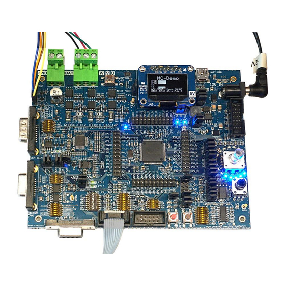
Default jumper setting (Power Supply by E1 or E2 emulator) is indicated by bold font. Note: 3.1.2 Board Overview Y-BLDC-SK-RH850F1KM-S1-V2 The RH850/F1KM-S1 Version of the V2 Starter Kit is shown in the figure below. Figure 1. Starter Kit top view RH850/F1KM-S1-V2 R12UT0015ED0100 Rev.1.00... -
Page 11: Starter Kit Hardware
RH850/F1KM-S1 (BLDC) Starter Kit V2 User's Manual 4. Starter Kit Hardware 4.1 Starter Kit functions 4.1.1 RH850/F1KM-S1 Starter Kit Figure 2. Functional overview Note: Modules with dashed lines are optional and not included in the kit. R12UT0015ED0100 Rev.1.00 Page 11... - Page 12 RH850/F1KM-S1 (BLDC) Starter Kit V2 User's Manual Functional Areas The functional areas provide various circuits and components useful for interacting with the microcontroller’s I/O: Motor control area Display area DC jack MC external power Mikrocontroller Power supply Debug UART/USB Pre drive unit...
-
Page 13: Power Supply
RH850/F1KM-S1 (BLDC) Starter Kit V2 User's Manual 4.1.2 Power Supply 4.1.2.1 Power supply configuration The Starter Kit provides three options for powering the board’s integrated circuits. It is possible to supply the Starter Kit by using the E1 or E2 debugging emulator or by connecting the provided external 12 Volt power supply to the DC jack. - Page 14 RH850/F1KM-S1 (BLDC) Starter Kit V2 User's Manual Table 7. Jumper setting for external 12 volt power supply Jumper Description Setting Note 1-2, BAT – MOT_VDD MOT_VDD selector closed 2-3, 12V – MOT_VDD open When the board is supplied by the provided power supply and an external power supply (not provided), please choose the following jumper settings: Table 8.
-
Page 15: Leds
RH850/F1KM-S1 (BLDC) Starter Kit V2 User's Manual 4.1.3 LEDs 4.1.3.1 RGB LED A RGB LED is provided to allow visual observation of microcontroller output port state and to show the functionality of the PWM diagnostic macro. The RGB LED, which is part of the rotary encoder, is driven by three N-channel transistors. -
Page 16: Digital Inputs For Low Power Sampler (Lps)
RH850/F1KM-S1 (BLDC) Starter Kit V2 User's Manual 4.1.3.4 Blue LED Circle Sixteen blue LEDs are driven by the TLC5925, which can be controlled by the SPI command to change the output states. Table 14. Blue LED Circle Signals Jumper Setting... -
Page 17: Pushbutton Switches
RH850/F1KM-S1 (BLDC) Starter Kit V2 User's Manual 4.1.5 Pushbutton Switches Two pushbutton switches (S1, S2) are provided to allow the switching of microcontroller input port states. Those switches are active low and normally open. A third pushbutton switch is used to switch off the motor control area when powered by the provided external power supply via the DC jack. -
Page 18: Rotary Encoder With Pushbutton Switch
DB9 connector and also comes with a sample software, to evaluate the SENT messages from a Renesas ZSSC4161 signal conditioner IC. You can connect the Pin 1 of CN5 directly to VDD_5V by closing switch 6 of S5. If you want to control the power supply to the Pin 1 of CN5 by a port pin, you must open the switch 6 of S5. - Page 19 RH850/F1KM-S1 (BLDC) Starter Kit V2 User's Manual Please close the following jumpers to connect the SENT interface to the microcontroller: Table 23. SENT Jumper Configuration Jumper Description Setting Note SENT SPCO P9_1 SENT interface connector SENT RX P9_0 SENT PROG ...
- Page 20 Additionally, it is possible to supply UART signals instead of the CAN signals to the CAN1 transceiver. This is intended to use a UART-over-CAN interface for external devices (e.g. Renesas UART-over-CAN position sensors). To choose the UART signals instead of the CAN signals, switch S7 must be configured accordingly. Only CAN1 connector supports the possibility to use UART signals instead of CAN signals.
-
Page 21: On-Chip Debug And Flash Programming Connector
Connector CN1 is a 14 pin, 0.1” pin pitch connector. The pinout of this connector supports the Renesas E1 or E2 On-chip debug emulator. For more information about E1 or E2, please see Chapter 5.1 E1 On-Chip Debug Emulator [R0E000010KCE00] or 5.2 E2 Emulator [RTE0T00020KCE00000R] (Successor of E1). -
Page 22: Oled Board (Optional)
The Predriver is described under 4.1.12 Predrive Area. The power stage area is a complete 3-phase bridge composed with discrete low voltage and high current MOSFETs. The MOSFETs are the Renesas NP75N04YUG n-channel power MOSFETs. The Gate of the MOSFETs is directly connected to the Predriver. - Page 23 RH850/F1KM-S1 (BLDC) Starter Kit V2 User's Manual Table 30. Analog Input Switch S10 Configuration Switch Description Setting Note SENSOR_SINP Fast Position Sensor signals to 1 = on AP0_10 MCU analog input signals M_BEU 2 = off SENSOR_SINN...
- Page 24 RH850/F1KM-S1 (BLDC) Starter Kit V2 User's Manual Caution: The Starter Kit is designed and intended to use with the delivered components. If you want to connect your own motor, please be informed that this happens on your own responsibility! Always stay within the specified voltage and current ranges!
- Page 25 RH850/F1KM-S1 (BLDC) Starter Kit V2 User's Manual SCL / UART_RX / CAN_L Select signal by exclusively closing switch: S8_4: P0_12 / RIIC0SCL S8_5: P0_4 / RLIN31RX (SELDP0) S8_6: CANL (IC8_6) SINP Connect this pin to MCU port AP0_10 by exclusively closing switch S10_1. Open switch S10_2 to disconnect the back-EMF signal M_BEU from the MCU port.
-
Page 26: Predrive Area
RH850/F1KM-S1 (BLDC) Starter Kit V2 User's Manual IRQ / SENT / PWM Select signal by exclusively closing switch: S9_1: P10_11 / INTP11 / TAUB0I1(PWM) S9_2: SENT Close S9_3 to connect this pin to MCU port P0_11 / RIIC0SDA Close S9_4 to connect this pin to MCU port P0_12 / RIIC0SCL... - Page 27 RH850/F1KM-S1 (BLDC) Starter Kit V2 User's Manual Please find below the connection between the MCU and the Predriver. Table 35 Predriver connection Description Connection MCU <-> Predriver Predriver-Input for UT Signals P10_0 <-> IUT Predriver-Input for UB Signals P10_1 <-> IUB Predriver-Input for VT Signals P10_2 <->...
-
Page 28: Development Tools
The E1 On-Chip Debug Emulator is a powerful debugging tool with flash programming functions which supports various Renesas microcontrollers. Updates and User Manuals for this tool can be found on the Renesas website: http://www.renesas.com/e1 5.2 E2 Emulator [RTE0T00020KCE00000R] (Successor of E1) The E2 On-Chip Debug Emulator is a powerful debugging tool with flash programming functions which supports various Renesas microcontrollers. -
Page 29: Rh850/F1Km-S1 Starter Kit Example Software
6.1 Framework Description Renesas provides a software framework with its Starter Kits, so that the customer can easily access and use the modules of the controller. The Starter Kits are equipped with a lot of peripheral devices like encoder, potentiometer, LEDs, display, CAN-, LIN- and UART/USB-transceivers, buttons and an optional motor control part. -
Page 30: Sample Software Classic
RH850/F1KM-S1 (BLDC) Starter Kit V2 User's Manual The framework is divided in 3 layers: Figure 4. Framework Layers In the peripherals layer you can find the source code related to the peripherals of the microcontroller. For example, you can find all related functions for the ports in the “r_port.c”. Only the functions defined in this source file should set or read the port registers. -
Page 31: Start Up Test
RH850/F1KM-S1 (BLDC) Starter Kit V2 User's Manual For live documentation of the RH850 actions connect a USB-Port of your computer via a USB Cable to the USB connector “ 18” of the board. You can use a terminal program like “putty” to receive the messages. - Page 32 RH850/F1KM-S1 (BLDC) Starter Kit V2 User's Manual R12UT0015ED0100 Rev.1.00 Page 32 June 07, 2021...
-
Page 33: Mode 1
RH850/F1KM-S1 (BLDC) Starter Kit V2 User's Manual 6.4 Mode 1 LED1 and LED2 glow in different intensities depending on the potentiometer POT1 position. The converted analog value of POT1 is used to update the duty cycle of the PWM module which drives these LEDs. -
Page 34: Standby
SW was in before standby was entered. 6.7 Motor Control Software Example On the RH850/F1KM-S1 Starter Kit V2 , a field-oriented-control motor control (FOC) example software will be flashed to the controller by default. This software is described in detail in the “Motor Control Application Note”, which is why it is only described in a brief way here. - Page 35 RH850/F1KM-S1 (BLDC) Starter Kit V2 User's Manual Display Description The display shows some information about the main motor control parameters which are described below: Table 36. Display Description Name Meaning RPMD Rotation Per Minute Desired RPMA Rotation Per Minute Actual...
-
Page 36: Component Placement And Schematics
RH850/F1KM-S1 (BLDC) Starter Kit V2 User's Manual 7. Component Placement and Schematics 7.1 Component placement DISP1 UART USB MOTOR R130 HALL IN 12V IN R132 R131 BA T MOT VDD LED20 LED1 R111 R112 N.C. R1 5 HALLC HALLB HALLA... -
Page 37: Schematics
RH850/F1KM-S1 (BLDC) Starter Kit V2 User's Manual 7.2 Schematics VDD_5V VDD_5V VDD_5V VDD_5V LED and Encoder VDD_5V 10µF/10V/X7R VDD_5V ENC1 PEL12T-4225S-S1024 VDD_5V VDD_5V 0.1uF 0.1uF 0.1uF 0.1uF 100k 100k VDD_5V 0.1uF EVCC VDD_5V MCP6544-I/ST M_LEDR_FB FB.R 0.1uF LED1 LED2 LED3... -
Page 38: Revision History
RH850/F1KM-S1 (BLDC) Starter Kit V2 User's Manual Revision History RH850/F1KM-S1 (BLDC) Starter Kit V2 User Manual: Hardware Rev. Date Description Page Summary ─ 1.00 April 2021 First edition issued 1.01 June 2021 5, 33 SENT Documents added, Motor Control Software description updated R12UT0015ED0100 Rev.1.00... - Page 39 RH850/F1KM-S1 (BLDC) Starter Kit V2 User Manual: Hardware Publication Date: Rev.1.00 June 2021 Published by: Renesas Electronics Europe...
- Page 40 SALES OFFICES Refer to "http://www.renesas.com/" for the latest and detailed information. Renesas Electronics America Inc. 2880 Scott Boulevard Santa Clara, CA 95050-2554, U.S.A. Tel: +1-408-588-6000, Fax: +1-408-588-6130 Renesas Electronics Canada Limited 1101 Nicholson Road, Newmarket, Ontario L3Y 9C3, Canada...
- Page 41 RH850/F1KM-S1 (BLDC) Starter Kit V2 RH850...
Need help?
Do you have a question about the RH850/F1KM-S1 and is the answer not in the manual?
Questions and answers