Table of Contents
Advertisement
Quick Links
Advertisement
Table of Contents

Related Manuals for Magnum Industrial MI-51260


Summary of Contents for Magnum Industrial MI-51260
- Page 1 MODEL NO.: MI-51260 OPERATING MANUAL...
-
Page 2: Table Of Contents
TABLE OF CONTENTS PREFACE ......................2 SYMBOLS DEFINITIONS ..................2 GENERAL SAFETY RULES FOR WOODWORKING MACHINERY ....3 ADDITIONAL SAFETY RULES FOR CIRCULAR SAWS ........4 ASSEMBLY INSTRUCTION .................. 5 SPECIFICATIONS ....................1 ELECTRICAL ......................2 BLADE INFORMATION ..................4 GLOSSARY OF TERMS FOR WOODWORKING.......... -
Page 3: Preface
PREFACE Thank you for choosing thistilting arbor table saw. We are pleased to offer you our best machinery and service, and trust that you will find our machinery economical, productive and easy to operate. This manual covers the proper operation, safety and maintenance of the machine. It is important that this manual be read in its entirety before operating the machine. -
Page 4: General Safety Rules For Woodworking Machinery
GENERAL SAFETY RULES FOR WOODWORKING MACHINERY There is a certain amount of hazard involved with the use of woodworking machinery. Using the machine with the respect and caution demanded as far as safety precautions are concerned will considerably lessen the possibility of personal injury. However, if normal safety precautions are overlooked or ignored, several personal injury to the operator can occur. -
Page 5: Additional Safety Rules For Circular Saws
18. AVOID ACCIDENTAL STARTING. Make sure switch is in “OFF” position before plugging in cord. 19. NEVER STAND ON TOOL. Serious injury could occur if the tool is tipped or if the cutting tool is accidentally contacted. 20. CHECK DAMAGED PARTS. Before further use of the tool, a guard or other part that is damaged should be carefully checked to ensure that it will operate properly and perform its intended function-check for alignment of moving parts, binding of moving parts, breakage of parts, mounting ,and any other conditions that may affect its operation. -
Page 6: Assembly Instruction
NEVER reach behind or over the cutting tool with either hand for any reason. MOVE the rip fence out of the way when cross cutting. WHEN cuttingmolding. NEVER run the stock between the fence and the moldingcutter head. Refer to molding applications in instruction Manual for details. DIRECTION OF FEED. -
Page 7: Specifications
SPECIFICATIONS MODEL MI-51250A Speed 4000R.P.M Diameter of arbor 5/8”(16mm) Diameter of cut 10”(254mm) MAX. depth of cut 3-1/8”(79mm) MAX. Depth of cut at 45. 2-1/8”(54mm) Distance in front of blade 10.23”(260mm) Table (LXM) 686X512mm Extension wing(LXW) 686X305mm Motor 3HP(230V) NetWeight 185kg Gross Weight 206kg... -
Page 8: Electrical
ELECTRICAL SPEED AND WIRING EXTENSION CORDS The no-load speed of your table saw is Use only 3-wire extension cords that have 3- approximately 3600 rpm. This speed is not prong grounding plugs and 3-pole receptacles constant and decreases under a load or with that accept the tool’s plug, when using a lower voltage. - Page 9 Figure 1.1. It also has a grounding pin like Make sure the tool is connected to an the one shown. outlet having the same configuration as the plug. No adapter is available or should be used with this tool. If the tool must be reconnected for used on a different type of electric circuit, the reconnection should be made by qualified service personnel;...
-
Page 10: Blade Information
BLADE INFORMATION Maximum Blade Diameter 254mm(10in) Included Blade Information 10"x40T Blade Body Thickness 2.2mm Blade Kerf Thickness 3.0mm Arbor Size 5/8" Blade Requirements When choosing a main blade, make sure the blade size meets the requirements listed below. The thickness of the blade body and teeth can be measured with calipers or any precision measuring device. -
Page 11: Glossary Of Terms For Woodworking
GLOSSARY OF TERMS FOR WOODWORKING Anti-Kickback Pawls Molding A non-through cut that gives a varied shape to the Toothed safety devices behind the blade designed to workpiece and requires a special blade. stop a workpiece from being kicked back at the operator during a ripping operation. -
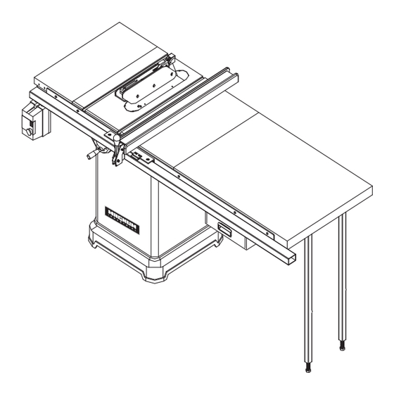
Page 12: Machine Legend
MACHINE LEGEND Handle Blade cover Extension Wing Riving knife M iter gauge Anti-kickback pawls Blade Front rail Rip fence Switch with key Rear rail Extension Wing Bevel lock handle Bevel lock handle Height hand wheel Rip fence handle Bevel hand wheel Side Extension Wing Drawer Bracket... - Page 13 OVERVIEW The upper position of the blade projects up through the table,surrounded by an insert called the thruplate. The height of the blade is set with a hand wheel on the front of the cabinet. To accommodate wide panels,the tabletop has extensions on each side. Detailed instructions are provided in the Operation section of this manual for the basic cuts:Cross cuts, miter cuts,bevel cuts,and compound cuts.
- Page 14 RIP FENCE HANDLE – The handle on the front of the rip fence releases the rip fence or locks it in place. RIVING KNIFE OR SPREADER – Located directly behind the blade,it keeps cut edges from binding and supports the blade guard. SCALE –...
-
Page 15: Operation Overview
OPERATION OVERVIEW To complete a typical operation, the operator does the following: 1. Examines workpiece to make sure it is suitable for cutting. 2. Adjusts blade tilt, if necessary, to correct angle for desired cut. 3. Adjusts blade height no more than 1⁄ "... -
Page 16: Assembleand Adjustments
ASSEMBLEAND ADJUSTMENTS ASSEMBLE THE RAISING AND TILTING HANDWHEELS AND LOCK KNOBS Place the wheels in position over the raising andtilting screws being sure to engage the slots, a (Fig.3), in back of each wheel with the roll pins, b(Fig.3), as shown at right. Screw on lock knobs c(Fig.4), to hold wheels in place, then attach silver handles, d(Fig.4) tightening them with the supplied 12mm combination wrench. - Page 17 ASSEMBLEAND ADJUSTMENTS CHECK HEELING (PARALLELING) MARKED TOOTH OF THE SAWBLADE TO THE MARKED TOOTH MITER GAGE GROOVE AT FRONT MITER GAGE GROOVE See Figures 7 and 8. DO NOTloosen any screws until you have checked with a square and made sure adjustments are necessary.
-
Page 18: Assembleand Adjustments
ASSEMBLEAND ADJUSTMENTS CHECKING SQUARENESS OF EXTENSION TABLES SAW TABLE See Figure 9 and 10. The extension wing should be checked for squatness to the saw table for smooth operation of the rip fence and rails. Place a square on the saw table, with the short end up and check .The long end of the square shouldextend across one of the extension wing. -
Page 19: Assembleand Adjustments
ASSEMBLEAND ADJUSTMENTS CHANGING THE SAW BLADE. Attention: left hand thread. Remove the arbor nut (J) and flange (I). Place saw blade on arbor shaft making sure teeth point down at the front of the saw. Reinstall flange and arbor nut and securely tighten. Remove the locking pin (K). - Page 20 The handle(L) should keep up as Fig.13. When install the riving knife. Then fix the handle(L) by rotation after riving knife installation as Fig.14. Fig. 13 Fig. 14 TO ADJUST THE RIVING KNIFE: 1. Disconnect the saw from the power source. 2.
- Page 21 6. Use the set screws shown in Figure 17 to adjust the riving knife bracket and re-install the riving knife. Fig.17(set screw for adjusting riving knife) 7. Repeat step 3-7 until the riving knife is centered on the blade and aligned at 90∘to the table. 8.
- Page 22 4. Put down the guards(N) as Fig.20 and lock the handle(M), then fix the handle(M) as Fig.21. Fig.20 Fig.21 setting. Tilt the blade with the bevel hand wheel as far as it will go to the left. Place Check the 45 the square against the blade (be sure the square is not against one of the saw teeth).
- Page 23 SWITCH INSTALLATION: Install the switch on the location as Fig.23 with the hex. Screw M8xp1.25x12. Lock the screw on the extension wing . Fig.23 POWER SWITH PADLOCK To avoid accidental staring by young children or others not qualified to use the tool, the use of a padlock is required.
-
Page 24: Adjusting The Miter Gauge
ADJUSTING THE MITER GAUGE See Figure 25. You can set the miter gauge at 0 and plus or minus 45 with the miter gauge stop pin and adjustable stop screws. Note: The miter gauge provides close accuracy in angled cuts. For very close tolerances, test cuts are recommended. -
Page 25: Kickbacks
KICKBACKS Kickbacks can cause serious injury. A kickback occurs when a part of the workpiece binds between the saw blade and the rip fence, or other fixed object, rises from the table and is thrown toward the operator. The risk of kickback can be minimized by attention to the following instructions. HOW TO REDUCE THE RISK OF KICKBACKS AND PROTECT YOURSELF FROM POSSIBLE INJURY: Be certain that the rip fence is parallel to the saw blade. -
Page 26: Cutting Aids And Accessories
CUTTING AIDS AND ACCESSORIES PUSH STICK In order to operate your table saw safely, you must use a push stick whenever the size or shape of the workpiece would otherwise cause your hands to be within 6-inches (152mm) of the saw blade or other cutter. A push stick is included with this saw. - Page 27 unless the workpiece is large enough to allow you to hold it more than 6 inches (152 mm) from the table. Before leaving the saw unattended, lock out power switch, or take other appropriate measures to prevent unauthorized use of the saw. Fig.27 RIP CUTS Remove miter gauge.
- Page 28 13. Do not push or hold onto the free or cut-off side of the workpiece. 14. Continue pushing the workpiece until it is clear of the blade. Do not overload the motor by forcing the workpiece into the blade. 15. When cut is complete, turn saw off. Wait for blade to come to a complete stop before removing workpiece from table.
- Page 29 Turn saw on. Let blade build up to full speed before moving workpiece into the blade. 10. Hand closest to blade should be placed on miter gauge lock knob and hand farthest from blade should hold workpiece firmly against the miter gauge face. Do not push or hold onto the free or cut-off side of the workpiece.
-
Page 30: Maintenance
MAINTENANCE △ WARNING: To reduce the risk of injury, turn unit off and disconnect it from power source before cleaning or servicing, before installing and removing accessories, before adjusting and when making repairs. An accidental start-up can cause injury KEEP MACHINE CLEAN Periodically blow out all air passages with dry compressed air. -
Page 31: Assembly Diagram
ASSEMBLY DIAGRAM... - Page 36 Bolt package and scales are located inside FRONT " FENCE GUIDE # D15 remove plastic end cap to access "...
- Page 37 PARTS LIST FOR MI-51260 PART NO. DESCRIPTION Q'TY MI-51100A-1 13300001P Table MI-51100A-2 E1310002 Extension wing MI-51100A-3 12700003b Table insert MI-51260-4 13300002c Cabinet MI-51100A-5 13200004 Motor cover MI-51100A-6 10105056a handle MI-51100A-7 13300032 Hand wheel HAND WHEEL OLD STYLE sn # < 51027918...
- Page 38 PARTS LIST FOR MI-51260 PART NO. DESCRIPTION Q'TY MI-51100A-48 12700058 Riving knife Handle MI-51100A-49 S009AN04 MI-51100A-50 11102020 Hex. Screw w. washer MI-51100A-51 11105080 Spring MI-51100A-52N C9001920 Bearing MI-51100A-53 13200038 Screw bushing MI-51100A-54 12900037 Sleeve MI-51100A-55 12700013 Shaft MI-51100A-56 C1206202A Bearing...
- Page 39 PARTS LIST FOR MI-51260 PART NO. DESCRIPTION Q'TY MI-51100A-101 13200041 Push handle MI-51100A-102 10102032 Spring MI-51100A-103 S0120400M Locking nut M4XP0.7 MI-51100A-104 S0310325 Pin Ø3X25 MI-51100A-105 S0010520M Cap screw M5XP0.8X20 MI-51100A-106 S0230500M Spring washer Ø5 MI-51100A-107 S0020640M Hex. Screw M6XP1.0X40 MI-51100A-108 S0110600M Hex.
- Page 40 PARTS LIST FOR MI-51260 PART NO. DESCRIPTION Q'TY MI-51100-A9 S0030508M Philip Hd. Screw M5xp0.8x8 MI-51100-A10 S0120200 Locking nut 1/4"-20UNC MI-51100-A11 S0040412 Flat Hd. Screw 1/4"-20UNCX5/8" MI-51100-A12 S0210404 Flat washer 1/4"X23X3t MI-51100-A14 S0313528 Pin Ø3.5-28 MI-51100-A15 S0310536 Pin Ø5-36 MI-51100-A17 12700051a...
- Page 41 PARTS LIST FOR MI-51260 PART NO. DESCRIPTION Q'TY MI-51100A-C11 11020011 Left Side Plate MI-51100A-C12 11020012 Right Side Plate MI-51100A-C13 S0110500 MI-51100A-C14 11001020G ADJUSTMENT BOLT MI-51100A-C16 11020013 Nylon Adjustment Screw MI-51100A-C17 S0050505e Socket Set screw MI-51100A-C18 S0310428 Spring Ping MI-51100A-C19 S0060511...
Need help?
Do you have a question about the MI-51260 and is the answer not in the manual?
Questions and answers