Table of Contents
Advertisement
Quick Links
Advertisement
Table of Contents

Related Manuals for Magnum Industrial MI-91340


Summary of Contents for Magnum Industrial MI-91340
- Page 1 MODEL NO.: MI-91340 OPERATING MANUAL...
-
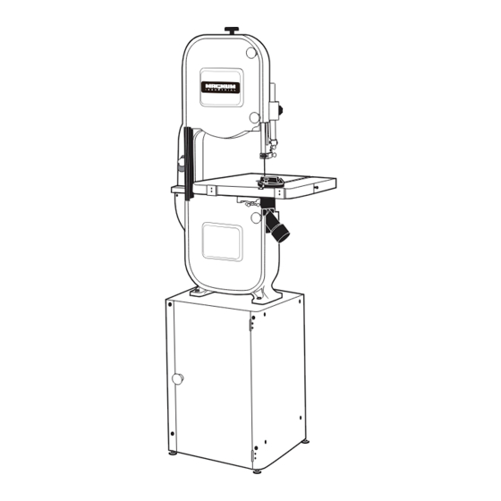
Page 2: Identification Of Main Parts And Components
IDENTIFICATION OF MAIN PARTS AND COMPONENTS FRONT VIEW BLADE TENSION ADJUSTMENT KNOB BLADE GUARD LOCK KNOB UPPER BLADE GUIDE ASSEMBLY BLADE GUARD MITER GAUGE TABLE ALIGNMENT PIN DUST PORT BASE CABINET TABLE TILT LOCK KNOB LOWER WHEEL COVER DOOR ON/OFF SWITCH W/SAFETY KEY UPPER WHEEL COVER DOOR REAR VIEW BLADE TRACKING ADJUSTMENT KNOB... - Page 3 UNPACKING Carefully unpack and remove the unit and its components from its shipping container and check for missing or damaged items as per the list of contents below. NOTE: Please report any damaged or missing items to your GENERAL® INTERNATIONAL distributor immediately. LIST OF CONTENTS Once the parts have been removed from the packaging , you should have the following items:...
- Page 4 To avoid eye injury from blowing debris, wear safety goggles when blowing out sawdust. 3. Keep the machine clean and free of sawdust. Frequently blow out or vacuum up the sawdust and wipe down the machine occasionally with a damp rag. Note: The wheels must always be kept clean.
-
Page 5: Removing / Installing The Blade
REMOVING / INSTALLING THE BLADE Your bandsaw is designed to handle several blade widths ranging from 1/4” and 3/8” used for tight radius curves, up to 1/2” and 3/4” for larger radius curves or for cutting thicker stock. BLADE CLEARANCE Note: When performing blade installation, removal, tensioning or tracking, maximum clearance between the blade and both upper and lower blade guide assemblies is required to minimize friction, which would be damaging to the blade. -
Page 6: Adjusting The Blade Guard For Depth Of Cut
ADJUSTING THE BLADE GUARD FOR DEPTH OF CUT The blade guard can be moved up or down to accommodate the height of the work to be cut. To prevent the blade (which is flexible and which would not otherwise be supported) from slipping out of position during cutting, and to reduce risks of injuries, a minimum amount of blade should be exposed. -
Page 7: Positioning The Lower Guide Blocks And Thrust Bearing
3. Pinch a feeler gauge C between one of the guide 5. Loosen the lower thumb screw F. blocks and the blade D, and then tighten the set 6. Turn the micro lower adjust nut G to move the guide screw E to set the gap between the guide block block assembly in or out until the guide blocks are and the blade. -
Page 8: Cutting Curves
CUTTING CURVES • When cutting curves, carefully turn the workpiece so the blade follows without twisting. If the curve is so sharp that you repeatedly back up and cut new kerf, use a narrower blade, or a blade with more set (teeth further apart). When a blade has more set, the workpiece turns easier but the cut is rougher. -
Page 9: Assemble The Base Cabinet
ASSEMBLY INSTRUCTIONS SERIOUS PERSONAL INJURY COULD OCCUR IF YOU CONNECT THE MACHINE TO THE POWER SOURCE BEFORE YOU HAVE COMPLETED THE INSTALLATION AND ASSEMBLY STEPS. DO NOT CONNECT THE MACHINE TO THE POWER SOURCE UNTIL INSTRUCTED TO DO SO. ASSEMBLE THE BASE CABINET 1. -
Page 10: Attaching The Table-Tilt Bracket
I N S TA L L T H E B A N D S AW O N TO T H E B A S E CABINET The bandsaw mounts onto a base cabinet which provides storage space for the miter gauge and replacementblades. Important! Make sure all stand fasteners are firmly tightened and that the stand cabinet is installed on a solid, flat and stable floor that is able to support... -
Page 11: Attaching The Table
ATTACHING THE TABLE 1. Remove the red insert A from the center of the 2. Turn the table right side up. Verify that the long table and the table alignment pin B from the table bolts C in the center of each trunnion are pointing slot. -
Page 12: Recommended Adjustments
RECOMMENDED ADJUSTMENTS ADJUSTING THE 90º TABLE STOP AND RE-ALIGNING THE ANGLE POINTER To ensure that your 90º cuts are square and that angled cuts are accurate with the angle indicator scale, the table default position must be set to 90º to the blade and the angle indicator pointer must be set to read 0 when the table is in the default (90º) position. -
Page 13: Adjusting Blade Tracking
ADJUSTING BLADE TRACKING Blade tracking means centering the blade on the wheels A. Ideally, the blade should stay relatively centered on both the upper and lower wheels. Due to natural variations in castings, blade thickness or density and tire wear, absolute perfect centering alignment is rarely attainable. -
Page 14: Changing Speed Settings
CHANGING SPEED SETTINGS This model MI-91345 14" wood cutting bandsaw has 2 different speed settings; low and high. - Low speed is to be used for cutting soft woods over 4" in height or hard woods over 2" in height. - High speed is best for cutting soft woods under 4"... -
Page 15: Replacing The Wheel Tire
REPLACING THE WHEEL TIRE Wheel tires must be replaced if they get worn out or damaged. (If it is worn out, the blade will not track straight on the wheels.) Use a flat screwdriver to remove the tire from the groove on the wheel, then install a new tire. - Page 16 PART LIST FOR MI-91340...
- Page 17 PART LIST FOR MI-91340 REF.NO. ITEM NO. DESCRIPTION SPECFICATION Q'TY MI-91340-01 UPPER FRAME MI-91340-02 STAR KNOB 5/16"*1-1/4" MI-91340-03 HEX. NUT 3/16" MI-91340-04 GUIDE POST (V TYPE) MI-91340-05 POST SEAT Double Teeth) MI-91340-06 THUMB SCREW M6*16L MI-91340-07 BEARING SHAFT MI-91340-08 BLADE GUARD...
- Page 18 PART LIST FOR MI-91340 REF.NO. ITEM NO. DESCRIPTION SPECFICATION Q'TY MI-91340-44 HEX. SCREW 5/16"*1-1/4'' MI-91340-45 TRUNNION BRACKET MI-91340-46 STAR KNOB MI-91340-47 SPRING WASHER 1/4" MI-91340-48 SCALE MI-91340-49 HEX. SCREW 5/16"X3" MI-91340-50 C RING S-10 MI-91340-51 PHILLIPS HEAD SCREW 3/16"*3/8" MI-91340-52 HEX.
- Page 19 PART LIST FOR MI-91340 REF.NO. ITEM NO. DESCRIPTION SPECFICATION Q'TY MI-91340-88 MOTOR PULLEY 3" Ø50-Ø76 MI-91340-89 PHILLIPS HEAD SCREW /W WASHER 3/16"*3/8" MI-91340-90 SAFTY SWITCH 4P HY18xx MI-91340-91 TEETH WASHER MI-91340-92 V BELT A-26 MI-91340-93 FLANGE NUT 3/8" MI-91340-94 PHILLIPS HEAD SCREW /W WASHER 3/16"*3/8"...
- Page 20 PART LIST FOR MI-91340 REF.NO. ITEM NO. DESCRIPTION SPECFICATION Q'TY MI-91340-132 C RING S-22 MI-91340-133 SPRING WASHER MI-91340-134 PHILLIPS HEAD SCREW 3/16"*3/8" MI-91340-135 HINGE LOWER MI-91340-136 SPRING WASHER 3/4" MI-91340-137 HEX. NUT 3/4" MI-91340-138 FLAT WASHER 3/8"*27 MI-91340-139 HEX SCREW 3/8"*1-3/4"L...
Need help?
Do you have a question about the MI-91340 and is the answer not in the manual?
Questions and answers