Table of Contents
Advertisement
Advertisement
Table of Contents

Related Manuals for Magnum Industrial MI-51350


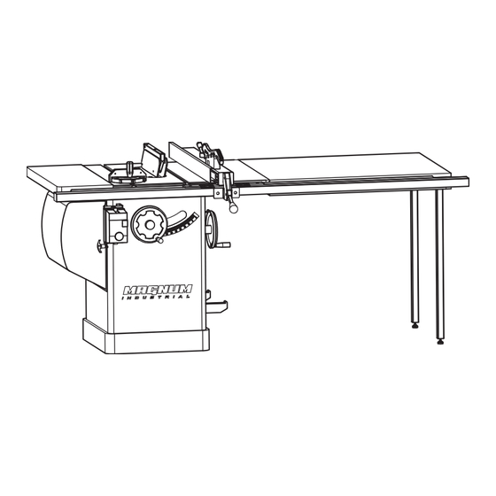
Summary of Contents for Magnum Industrial MI-51350
-
Page 1: Table Of Contents
MODEL NO.: MI-51350 & MI-51453 OPERATING MANUAL... -
Page 2: Table Of Contents
Table of Contents Table of Contents ............................. 2 Warnings ..............................3 Specifications ............................6 Shipping Contents ............................ 7 Unpacking ............................. 7 Cleaning ..............................7 Contents of the Shipping Container ...................... 8 Assembly ..............................9 Motor Cover ............................9 Handwheel Assembly ..........................9 Miter Gauge and Fence Storage Hooks .................... - Page 3 1. Read and understand the entire owner's manual before attempting assembly or operation. 2. Read and understand the warnings posted on the machine and in this manual. Failure to comply with all of these warnings may cause serious injury. 3. Replace the warning labels if they become obscured or removed. 4.
- Page 4 19. Keep visitors a safe distance from the work area. Keep children away. 20. Make your workshop child proof with padlocks, master switches or by removing safety keys. 21. Give your work undivided attention. Looking around, carrying on a conversation and “horse-play” are careless acts that can result in serious injury.
-
Page 5: Specifications
Specifications TSCE-10L Stock Number ......................MI-51350 (3 HP, 1 Ph) ..........................MI-51453 (5 HP, 1 Ph) Blade Diameter ........................... 10" Arbor Diameter ............................. 5/8" Maximum Depth of Cut ..........................3" Maximum Thickness at 45 Cut ......................2-1/8" Table in Front of Saw Blade at Maximum Cut ..................10"... -
Page 6: Shipping Contents
Shipping Contents Unpacking Remove box and wood crating completely from around saw. Check for shipping damage. Report any damage immediately to your distributor and shipping agent. Do not discard any shipping material until the Table Saw is assembled and running properly. Compare the contents of your container with the parts lists in the next two pages to make sure all parts are intact. -
Page 7: Contents Of The Shipping Container
Contents of the Shipping Container Extension Tables Main Saw Container Two extension tables are packaged in individual boxes. Table Saw (A) (One extension table with sliding table) Switch (B) Table Insert (C) Owner's Manual (D) ,QVSHFWLRQ 5HFRUG (not shown) Extension Tables Side Cover Box Side Cover Contents of Side Cover Box... -
Page 9: Extension Wing
Extension Wing Referring to Figures 4 and 5: Hardware: (6) 7/16”x1-1/2” Hex Cap Bolts, (6) 7/16” Lock Washers, (6) 7/16” Flat Washers & (2) Extension Tables Tools: 17mm Wrench, Straight Edge 1. Attach the left extension wing (A) table (B) with three each hex cap screws (E), lock washers (F) and flat washers (G). -
Page 10: Riving Knife And Guard Installation
Riving Knife and Guard Installation Description Referring to Figure 7: The complete riving knife and guard assembly is shown in A. Installation Referring to Figure 8: 1. Set the saw blade to the 90 degree position and raise it all the way (refer to Handwheel Figure 7 Adjustments on page 13). -
Page 11: Mounting Rails & Extension Table
Electrical Connections Mounting Rails & Extension Table With the extension wings properly aligned, the A qualified electrician must rail and fence assembly can now be mounted to complete all electrical connections! Failure the saw. Refer to the Rip Fence Owner's Manual to comply may result in serious injury! for mounting instructions for the rails, fence and optional wooden extension table. -
Page 12: Adjustments
Adjustments Handwheel Adjustments Referring to Figure 10: The front handwheel (B) controls the raising and lowering of the blade (blade height). The side handwheel (D) controls the blade tilt. The blade can be adjusted for a tilt between 90º (vertical or a setting of 0º on the scale) and 45º left tilt (D). -
Page 13: Riving Knife Adjustment
Riving Knife Adjustment Lateral alignment The saw blade and riving knife must be in line as close possible with each other (lateral alignment) for the prevention of kickback. Upon initial blade guard and riving knife installation no further adjustment should be necessary. Alignment should be checked and adjusted, if required, after each blade change. -
Page 14: Blade Alignment
4. Tighten the socket head flat screws ( (E). 5. Reinsert the riving knife; tighten the lock handle (A, Fig. 14) and check that the saw blade/knife gap is between 3 - 8mm (Figure 16). Note: Attempt to make the gaps as even as possible. -
Page 15: Adjusting 45 And 90 Positive Stops
Adjusting 45 and 90 Positive Stops The stops have been adjusted at the factory. After a period of use, or, after moving the saw to another location, the stops may no longer be set properly. To check and adjust the stops: Tools: 12mm wrench, combination square 1. -
Page 16: Changing The Belt
Changing the Belt Make all machine adjustments or maintenance with the machine unplugged from the power source. Failure to comply may cause serious injury! Referring to Figure 22: 1. Disconnect the machine from the power source, unplug. 2. Lower the blade to its lowest point. 3. -
Page 17: Troubleshooting
Troubleshooting Trouble Possible Cause Solution Overload tripped Allow motor to cool and reset by pushing off switch Saw stops or will Check all plug connections Saw unplugged from wall or motor not start Fuse blown or circuit breaker tripped Replace fuse or reset circuit breaker Cord damaged Replace cord Stops not adjusted correctly... - Page 18 Table and Cabinet Assembly (Flat Front Type)
- Page 19 Table and Cabinet Assembly (Flat Front Type) lndex Part Description Size Qty. 1………… MI-51350-1…………….…… Lock Knob………………. ……………… .…1 2………… MI-51350-2………………… Miter Gauge Body.……… ……………..…1 3………… MI-51350-3………………… Hex Nut………………….. M5…………. .…3 4………… MI-51350-4………………… Pointer…………………… ……………..…1 5………… MI-51350-5………………… Stop Link………………...
- Page 20 Table and Cabinet Assembly (Flat Front Type) lndex Part Description Size Qty. 28……….. MI-51350-28 …..……………. Tilt Scale…………………… ……………..…1 29……….. MI-51350-29 …..……………. ……………..…1 Set Screw………………… 30……….. MI-51350-30 ………………... Power Cord………………... 14GA x 3C….. .…2 MI-51453-30 ………………... Power Cord………………... 14GA x 4C….. .…2 1/4”...
- Page 21 Motor and Trunnion Assembly Breakdown (Left tilt)
- Page 22 Key..…….……………….. M5x44… ..... 1 ..106.…….. MI-51350-106………………... Ball Bearing……...……… 6203zz ....2 ..107…….. MI-51350-107………………… Bearing Load Spring .......... 4 ..108…….. MI-51350-108………………… Bearing Load Spacer ......... 4 ..109…….. MI-51350-109………………… Set Screw……………….. 1/4”x3/8”…..10 110.…….. MI-51350-110………………… Arbor Pulley ............. 1 111.……..
- Page 23 Part Description Size Qty. 121.…….. …………….. Shaft………………………... …………….. .…1 MI-51350-121 122.…….. Motor Bracket…………….. …….…….… .…1 MI-51350-122……………. 123.…….. Pin………………………….. …….…….… .…1 MI-51350-123……………. 124.…….. Spring Clip.………………... …………..… .…2 MI-51350-124……………. 125.…….. 125…………….. PJ260..…..… .…1 MI-51350- Poly V-Belt………………… 126.…….. Motor Plate………………... …………….. .…1 MI-51350- 126……………….
-
Page 24: Motor And Trunnion Assembly Breakdown
168………………. 169.…….. MI-51350- Tilt Shaft…..……………….. …..………… .…1 169………………. 170.…….. MI-51350- Wrench……...……………... ……………..…1 170………………. 171..…….. MI-51350- 171……………... Hose……………………...… ………..…… ….1 172.…….. MI-51350- 172……………... Plate………………………... ……………..…1 173.…….. MI-51350- 173……………... Hex Socket Cap Screw..…... 5/16”x3/4”… ….3 174……… MI-51350- 174……………... Chip Plate………………….. - Page 25 Motor and Trunnion Assembly Breakdown lndex Part Description Size Qty. 180.…….. MI-51350- 180……………... Spring………..……….……. …………….. .…1 181.…….. MI-51350- 181……………... Nylon Nut………………….. 1/4”…..….… .…3 182.…….. MI-51350- 182……………... …….…….… .…2 Spring……………...………. 183.…….. MI-51350- 183……………... Guide Bracket...…….……... …………..… .…1 184.…….. MI-51350- 184……………... Flat Head Screw……………...
- Page 26 Blade Guard Assembly...
-
Page 27: Blade Guard Assembly
Description Size Qty. 1…….…… MI-51350-1B………………… Riving Knife ............1 Blade Guard Body …………M3x12 ..... 1 2…….…… MI-51350-2B………………… 3…….…… MI-51350-3B………… ……… Bushing(L) …………………. M63 ......1 Bushing(R) …………………. E5 ......1 4…….…… MI-51350-4B………………… Flat Head Screw …………….M3x10……………..4 5…….…… MI-51350-5B………………… 6…….…… MI-51350-6B…………………... -
Page 28: Wiring Diagrams
Wiring Diagrams 3HP, 230V, 1Phase... -
Page 29: Blade Guard Parts And Assembly
5HP, 230V, 3Phase... -
Page 30: Fence Assembly
Fence Assembly... - Page 31 Fence Assembly lndex Part Description Size Qty. 1………… MI-99502-1F… ……. Fence Body Assembly……………... ……………... ….1 2………… MI-99502-2F… ……. Round Head Screw………………... M5×8………. ….4 3………… MI-99502-3F… ……. Flat Washer………………………... M5…………. ….4 4………… MI-99502-4F… ……. Hex Nut……………………………. M5…………. ….4 5………… MI-99502-5F… ……. Push Stick………………………….. ……………... ….1 6…………...
- Page 32 Fence Assembly lndex Part Description Size Qty. 34……….. MI-99502-34F… ……. Hex Nut……………………………. M6…………. ….8 35……….. MI-99502-35F… ……. Foot…………………………………. 5/16”×2” ….. ….1 36……….. MI-99502-36F… ……. Lock Pin……………………………. M5×12…….. ….2 37……….. MI-99502-37F… ……. Pad…………………………………. ……………... ….1 38……….. MI-99502-38F… ……. Handle Bar………………………… ……………... ….2 39………..
-
Page 33: Rail Assembly
Rail Assembly... - Page 34 Rail Assembly lndex Part Description Size Qty. 1………… MI-99502-1R……….. Front Rail………………………….. ……………... ….1 2………… MI-99502-2R……….. Flat Head Screw…………………… 1/4”×1-1/2”... ….4 3………… MI-99502-3R……….. Flat Washer………………………... 1/4” ………..28 4………… MI-99502-4R……….. Lock Washer………………………. 1/4” ………..22 5………… MI-99502-5R……….. Hex Nut…………………………….. 1/4” ………..14 6…………...
Need help?
Do you have a question about the MI-51350 and is the answer not in the manual?
Questions and answers