Table of Contents
Advertisement
Quick Links
Advertisement
Table of Contents

Related Manuals for SKF EWT


Summary of Contents for SKF EWT
- Page 1 Operating Instructions EWT; EXZT; IG; IGZ; IZ Universal control unit for industrial lubrication systems Created on: 28.02.2022 Document no.: 951-180-192-EN Version: Read these instructions before installation or start-up of the product and keep them readily available for later consultation!
-
Page 2: Directive 2014/30/Eu, Annex Iv
Manager, SE Germany Berlin Manufacturer: SKF Lubrication Systems Germany GmbH, Motzener Strasse 35/37, 12277 Berlin, Germany UK Declaration of Conformity pursuant to the Electromagnetic Compatibility Regulations 2016 No. 1091, Annex IV The manufacturer hereby declares under its sole responsibility conformity of the product described below with all relevant harmonization legislation of the United Kingdom at the time of placing on the market. -
Page 3: Masthead
Training www.skf.com/lubrication We conduct detailed training in order to enable maximum safety and efficiency. We recommend taking advantage of this training. Berlin Plant For further information, contact your authorized SKF dealer or Motzener Strasse 35/37 the manufacturer. 12277 Berlin Germany Tel. -
Page 4: Table Of Contents
5.2.2 Control units for oil+air lubrication systems ..57 Table of contents 5.2.3 Control units for progressive metering systems .. 65 5.2.4 Control units for combined circulating and piston EU Declaration of Conformity in accordance with metering device systems ........... 81 Directive 2014/30/EU, Annex IV ........ -
Page 5: Safety Alerts, Visual Presentation, And Layout
1. Instruction steps: These indicate a chronological sequence Safety alerts, visual of instruction steps. The numbers of the steps are in bold and are followed by a period. If a new activity follows, the presentation, and layout numbering starts again at “1.” –... -
Page 6: Safety Instructions
1.2 Intended use 1. Safety instructions The product is intended solely for installation in another • Electrical devices must be kept in proper condition. This must machine. be ensured by periodic inspections in accordance with the Use is only permitted within the scope of commercial or relevant applicable standards and technical rules. -
Page 7: Safety Markings On The Product
• Cover hot or cold surfaces appropriately 1.6 Safety markings on the product Where applicable: No safety markings on the product • Depressurize • Isolate, lock and tag out • Check to ensure live voltage is no longer present NOTE •... -
Page 8: Overview, Functional Description
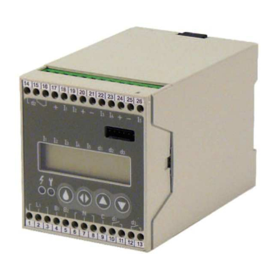
2. Overview, functional Figure 1 shows the design of the SKF universal control unit, version E, with its mounting dimensions. description The front side of the unit has a control screen (Fig. 1/5) and the service interface (Fig. 1/1). With version I, the control screen 2.1 Design... -
Page 9: Function
Table 3 The SKF universal control unit is equipped with powerful Comparison of the previous voltage codes and the new electronics that can perform various tasks for the control of SKF codes centralized lubrication systems. Which functions the unit Voltage code performs depends on the configured unit type. - Page 10 Interval time extension 2.2.5.2 Overview On some units, the input I3 can be used for stopping and Table 4 releasing the interval time countdown in the pulse generator operating mode. The interval time countdown stays interrupted Overview for as long as voltage is applied. Designation Short description Pulse generator operating mode...
- Page 11 Pump run time limitation • Pump run time limitation The pump run time (TL) is primarily limited by the monitoring • Pressure build-up monitoring time. • Pressure reduction monitoring (NO contact) • Fill level monitoring (NO contact) Pressure reduction monitoring •...
- Page 12 • Adjustable monitoring time Table 9 • Adjustable pump delay time IGZ36-20-S6 input functions • Pump run time limitation • Pressure build-up monitoring Input Setting Meaning • Fill level monitoring (NC contact) • Fill level warning NC contact • Interval time extension NO contact NO contact Input functions...
-
Page 13: Control Units For Oil+Air Lubrication Systems
Input functions 2.2.5.9 IG351-10 Table 13 Operating modes The IG351-10 unit can only be used as a pulse generator IGZ51-20-S3 input functions (operating mode B). Input Setting Meaning Functions The IG351-10 unit has the functions listed below: NO contact • Adjustable interval time NO contact •... - Page 14 Prelubrication The monitoring time is usually permanently set and cannot be Prelubrication is an operating time directly after the unit is modified by the operator. switched on. If a fault occurs during prelubrication, a fault signal Pump delay time is issued. The pump delay time is a period of time during which the pump The prelubrication cycle continues to run after reaching the required pressure in the...
-
Page 15: Control Units For Progressive Metering Systems
• Fill level monitoring 2.2.7 Control units for progressive metering • Power-failure memory (EEPROM) systems Input functions 2.2.7.1 Application On this unit, the input function of the lubricant level switch (WS) The control units described in this section are used for time or can be changed pulse dependent control of centralized lubrication systems with progressive metering devices. - Page 16 The interval time TP Pump run time limitation The interval time is the time between two operating times. The The pump run time (TL) is primarily limited by the monitoring length of the interval can be defined in two ways, resulting in time.
- Page 17 Input functions • Adjustable monitoring time • Adjustable number of strokes Table 16 • Pump run time limitation by stroke monitoring EXZT2A03 input functions • Fill level monitoring (NO contact) • Interval time extension Input Setting Meaning Input functions NO contact Table 18 NO contact NO contact...
-
Page 18: Control Units For Combined Circulating And Piston Metering Device Systems
• Power-failure memory 2.2.7.8 IGZ51-20-S7 Operating modes Input functions The IGZ51-20-S7 control unit can be used in the following Table 21 operating modes: A Pulse generator with continuous pump operation during the IGZ51-20-S8 input functions operating time Input Setting Meaning B Pulse generator with intermittent pump operation C Pulse counter with continuous pump operation during the operating time... -
Page 19: Pulse Monitors
triggers a lubrication after the set number of pulses. The Power-failure memory (EEPROM) operator can set the number of incoming pulses to be counted. The power-failure memory saves important data during an interruption in the power supply of the control unit, such as the Pulse monitoring remaining interval time or a fault signal. - Page 20 2.2.9.2 Overview 2.2.9.4 EWT2A01, EWT2A01-S1 Operating modes Table 24 The control units EWT2A01 and EWT2A01-S1 can only be Overview used in the pulse monitoring operating mode. Designation Short description Functions <Content> The units have the functions listed below: EWT2A01 Pulse monitor for up to 3 measuring points EWT2A01-S1 Like EWT2A01, but with lubrication pause EWT2A01 function;...
-
Page 21: Control Units For Chain Lubrication Systems
The input functions can be changed, except on the EWT2A04- 2.2.9.5 EWT2A04, EWT2A04-S1 S1 unit Operating modes The control units EWT2A04 and EWT2A04-S1 can only be 2.2.10 Control units for chain lubrication used in the pulse monitoring operating mode. systems Functions The units have the functions listed below: 2.2.10.1 Application... - Page 22 2.2.10.7 Monitoring time, pressure build-up 2.2.10.10 Fill level monitoring monitoring The fill level in the lubricant reservoir is monitored by means of a lubricant level switch (WS). The monitoring time (TU) is a time slot within the operating This switch is designed as an NC contact. This means that the time in which the pressure build-up in the lubricant lines is signal cables to the lubricant level switch are monitored for wire monitored.
-
Page 23: Overview
2.3 Overview Table 30 Overview of the available SKF control units Previous designation New designation Application EWT2A01 voltage EWT2A01-E Pulse monitor EWT2A04 voltage EWT2A04-E Pulse monitor EXZT2A02 voltage EXZT2A02-E Piston metering devices for single-line EXZT2A02-I systems EXZT2A03 voltage EXZT2A03-E Piston metering devices for single-line... -
Page 24: Parameter
Table 30 Overview of the available SKF control units Previous designation New designation Application IGZ51-2-S8 IGZ51-20-S8-E Progressive metering devices IGZ51-20-S8-I IZ361 IZ361-30-E Circulating and metering device lubrication IZ361-30-I IZ38-3 IZ38-30-I Piston metering devices for single-line IGZ38-30-E systems IGZ38-30-I IZ38-3-S1 IGZ38-30-E... - Page 25 2.4.1.3 EXZT2A07 Table 33 Parameters of the EXZT2A07 Designation Abbreviation Default Unit Setting range Unit Operating mode B (pulse generator) Interval time Seconds 01 E 00 - 99 E 04 (BA B) Seconds 01 E 00 - 99 E 04 (BA D) Pulses Monitoring time Seconds...
-
Page 26: Control Units For Oil+Air Lubrication Systems
2.4.1.7 IGZ51-20-S3 Table 37 Parameters of the IGZ51-20-S3 Designation Abbreviation Default Unit Setting range Unit Operating mode A (pulse generator with EEPROM) B (pulse generator without EEPROM) C (pulse counter with EEPROM) D (pulse counter without EEPROM) Interval time Minutes 01 E 00 - 99 E 04 (BA A, B) Minutes 01 E 00 - 99 E 04 (BA C, D) -
Page 27: Control Units For Progressive Metering Systems
2.4.3 Control units for progressive metering systems 2.4.3.1 EXZT2A03 Table 40 Parameters of the EXZT2A03 Designation Abbreviation Default Unit Setting range Unit Operating mode B (pulse generator) D (pulse counter) Interval time Seconds 01 E 00 - 99 E 04 (BA B) Seconds 01 E 00 - 99 E 04 (BA D) Pulses... - Page 28 2.4.3.4 IGZ51-20-S2 Table 43 Parameters of the IGZ51-20-S2 Designation Abbreviation Default Unit Setting range Unit Operating mode A (pulse generator with continuous pump operation) B (pulse generator with intermittent pump operation) C (pulse counter with continuous pump operation) D (pulse counter with intermittent pump operation) Interval time Minutes...
-
Page 29: Control Units For Combined Circulating And Piston Metering Device Systems
2.4.3.6 IGZ51-20-S8 Table 45 Parameters of the IGZ51-20-S8 Designation Abbreviation Default Unit Setting range Unit Operating mode A (pulse generator with continuous pump operation) B (pulse generator with intermittent pump operation) C (pulse counter with continuous pump operation) D (pulse counter with intermittent pump operation) Interval time Minutes... -
Page 30: Control Units For Chain Lubrication Systems
2.4.5.2 EWT2A04, EWT2A04-S1 Table 48 Parameter of the EWT2A04 and EWT2A04-S1 Designation Abbreviation Default Unit Setting range Unit Monitoring time Seconds 06 E 00 – 90 E 03 Seconds Limit value 1 10 E 04 *0.01 01 E 00 - 25 E 04 *0.01 Pulses / Pulses / minute... -
Page 31: Technical Data
3. Technical data Table 50 Technical data Version +471 Version +472 Nominal input voltage Un AC (100..120)V or AC DC 20..24V or (200..240)V AC 20..24V Rated input voltage 0.85Un to 1.1Un (85..132V / 0.85Un to 1.1Un (17..26.4V) 170..264V) Nominal input current 70mA / 35mA 75mA, at maximum output load: 250mA... -
Page 32: Delivery, Returns, Storage
4.4 Storage temperature range 4. Delivery, returns, storage For parts not filled with lubricant, the permitted storage 4.1 Delivery temperature is the same as the permitted ambient temperature range (see “Technical data”). After receipt of the shipment, it must be inspected for any shipping damage and for completeness according to the shipping documents. -
Page 33: Assembly
Because the version I control unit is supplied as part of a 5. Assembly compact unit, this chapter describes only the installation of version E of the control unit. First check the operating voltage range in which the unit will DANGER be used. -
Page 34: Assembly Information For Specific Unit Types
5.2 Assembly information for specific unit types 5.2.1 Control units for single-line systems After the unit is installed, the parameters are entered, and the operating voltage is applied, the functional sequence of the unit starts with prelubrication 5.2.1.1 EXZT2A02 Connection diagram Fig. - Page 35 Table 51 Connection diagram for EXZT2A02 Terminal Designation L1/N Operating voltage B1/B2 Link terminals for operating voltage range (shown: 200..240V) Lubricant level switch (shown: reservoir filled) Pressure switch (pressure build-up monitoring) Pressure switch (pressure reduction monitoring, shown: pressure reduced) Pushbutton 1.
- Page 36 5.2.1.2 EXZT2A05 Connection diagram Fig. 5 Connection diagram for EXZT2A05 * For connection of the 20..24V AC version, see section 5.3 Terminal assignment Table 52 Connection diagram for EXZT2A05 Terminal Designation L1/N Operating voltage B1/B2 Link terminals for operating voltage range (shown: 200..240V) Lubricant level switch (shown: reservoir filled)
- Page 37 Table 52 Connection diagram for EXZT2A05 Terminal Designation Pressure switch (pressure build-up monitoring) Pressure switch (pressure reduction monitoring) MKPV Machine contact/interval time extension MKUe Machine contact (pulse monitoring) Pushbutton 1. Intermediate lubrication 2. Reset fault +24V DC output 0V DC output Load contact for lubricant feed pump (SMFP) Changeover contact, command link Break contact: fault indication (StA)
- Page 38 5.2.1.3 EXZT2A07 Connection diagram Fig. 6 Connection diagram for EXZT2A07 * For connection of the 20..24V AC version, see section 5.3 Terminal assignment Table 53 Connection diagram for EXZT2A07 Terminal Designation L1/N Operating voltage B1/B2 Link terminals for operating voltage range (shown: 200..240V) Lubricant level switch (shown: reservoir filled)
- Page 39 Table 53 Connection diagram for EXZT2A07 Terminal Designation WS_V Lubricant level switch (fill level warning, shown: reservoir filled) Pressure switch (pressure build-up monitoring) MKPV Machine contact/interval time extension Pushbutton 1. Intermediate lubrication 2. Reset fault +24V DC output 0V DC output Load contact for lubricant feed pump (SMFP) Changeover contact, command link Break contact: fault indication (StA)
- Page 40 5.2.1.4 IGZ36-20 Connection diagram Fig. 7 Connection diagram for IGZ36-20 * For connection of the 20..24V AC version, see section 5.3 Terminal assignment...
- Page 41 Table 54 Connection diagram for IGZ36-20 Terminal Designation L1/N Operating voltage B1/B2 Link terminals for operating voltage range (shown: 200..240V) Lubricant level switch (shown: reservoir filled) Pressure switch (pressure build-up monitoring) Pressure switch (pressure reduction monitoring) Machine contact Pushbutton 1. Intermediate lubrication 2.
- Page 42 Pulse diagrams Fig. 8 Pulse diagrams (time axes not to scale) Legend to Figure 8: A Normal sequence B Sequence with fault, pressure not built up C Sequence with fill level fault d1 Pump motor, relay d2 Command link, relay DS Pressure switch (NO contact) DS2 Pressure switch (NC contact) WS Lubricant level switch (NO contact)
- Page 43 5.2.1.5 IGZ36-20-S6 Connection diagram Fig. 9 Connection diagram for IGZ36-20 * For connection of the 20..24V AC version, see section 5.3 Terminal assignment...
- Page 44 Table 55 Connection diagram for IGZ36-20-S6 Terminal Designation L1/N Operating voltage B1/B2 Link terminals for operating voltage range (shown: 200..240V) Lubricant level switch (shown: reservoir filled) Pressure switch (pressure build-up monitoring) Pressure switch (pressure reduction monitoring) Machine contact Pushbutton 1. Intermediate lubrication 2.
- Page 45 Pulse diagrams Fig. 10 Pulse diagrams (time axes not to scale) Legend to Figure 10: A Normal sequence B Sequence with fault, pressure not built up C Sequence with fill level fault d1 Pump motor, relay d2 Command link, relay DS Pressure switch (NO contact) DS2 Pressure switch (NC contact) WS Lubricant level switch (NC contact)
- Page 46 5.2.1.6 IGZ38-30 Connection diagram Fig. 11 Connection diagram for IGZ38-30 * For connection of the 20..24V AC version, see section 5.3 Terminal assignment...
- Page 47 Table 56 Connection diagram for IGZ38-30 Terminal Designation L1/N Operating voltage B1/B2 Link terminals for operating voltage range (shown: 200..240V) Lubricant level switch (shown: reservoir filled) Pressure switch (pressure build-up monitoring) Machine contact Pushbutton 1. Intermediate lubrication 2. Reset fault +24V DC output 0V DC output Load contact for lubricant feed pump (SMFP)
- Page 48 Pulse diagrams Fig. 12 Pulse diagrams (time axes not to scale) Legend to Figure 12: A Normal sequence B Sequence with fault, pressure not built up C Sequence with fill level fault d1 Pump motor, relay d2 Command link, relay DS Pressure switch (NO contact) WS Lubricant level switch (NC contact) DK Pushbutton...
- Page 49 5.2.1.7 IGZ38-30-S1 Connection diagram Fig. 13 Connection diagram for IGZ38-30-S1 * For connection of the 20..24V AC version, see section 5.3 Terminal assignment...
- Page 50 Table 57 Connection diagram for IGZ38-30-S1 Terminal Designation L1/N Operating voltage B1/B2 Link terminals for operating voltage range (shown: 200..240V) Lubricant level switch (shown: reservoir filled) Pressure switch (pressure build-up monitoring) Machine contact Pushbutton 1. Intermediate lubrication 2. Reset fault +24V DC output 0V DC output Load contact for lubricant feed pump (SMFP)
- Page 51 Pulse diagrams Fig. 14 Pulse diagrams (time axes not to scale) Legend to Figure 14: A Normal sequence B Sequence with fault, pressure not built up C Sequence with fill level fault d1 Pump motor, relay d2 Command link, relay DS Pressure switch (NO contact) WS Lubricant level switch (NC contact) DK Pushbutton...
- Page 52 5.2.1.8 IG351-10 Connection diagram Fig. 15 Connection diagram for IG351-10 * For connection of the 20..24V AC version, see section 5.3 Terminal assignment...
- Page 53 Table 58 Connection diagram for IG351-10 Terminal Designation L1/N Operating voltage B1/B2 Link terminals for operating voltage range (shown: 200..240V) Lubricant level switch (shown: reservoir filled) Pushbutton +24V DC output 0V DC output Load contact for lubricant feed pump (SMFP) Changeover contact, command link Break contact: fault indication (StA) Make contact: operation OK...
- Page 54 5.2.1.9 IGZ51-20-S3 Connection diagram Fig. 16 Connection diagram for IGZ51-20-S3 * For connection of the 20..24V AC version, see section 5.3 Terminal assignment...
- Page 55 Table 59 Connection diagram for IGZ51-20-S3 Terminal Designation L1/N Operating voltage B1/B2 Link terminals for operating voltage range (shown: 200..240V) Lubricant level switch (shown: reservoir filled) Pressure switch (pressure build-up monitoring) Pressure switch (pressure reduction monitoring) MKPV Machine contact/interval time extension Pushbutton 1.
- Page 56 Pulse diagrams Fig. 17 Pulse diagrams (time axes not to scale) Legend to Figure 17: A Normal sequence B Sequence with fault, pressure not built up C Sequence with fill level fault d1 Pump motor, relay d2 Command link, relay DS Pressure switch (NO contact) DS2 Pressure switch (NC contact) WS Lubricant level switch (NO contact)
-
Page 57: Control Units For Oil+Air Lubrication Systems
5.2.2 Control units for oil+air lubrication systems After the unit is installed, the parameters are entered, and the operating voltage is applied, the functional sequence of the unit starts with a prelubrication cycle 5.2.2.1 IG54-20 Connection diagram Fig. 18 Connection diagram for IG54-20 * For connection of the 20..24V AC version, see section 5.3 Terminal assignment... - Page 58 Table 60 Connection diagram for IG54-20 Terminal Designation L1/N Operating voltage B1/B2 Link terminals for operating voltage range (shown: 200..240V) Lubricant level switch (shown: reservoir filled) Pressure switch (pressure build-up monitoring) DS_L Pressure switch (air pressure monitoring) Pushbutton 1. Intermediate lubrication 2.
- Page 59 Pulse diagrams Fig. 19 Pulse diagrams (time axes not to scale) Legend to Figure 19: A Normal sequence B Fault, pressure not built up (DS or DS_L) C Sequence with fill level fault d1 Pump motor, relay d2 Command link, relay DS Pressure switch for oil (NO contact) DS_L Pressure switch for air (NO contact) WS Lubricant level switch (NO contact)
- Page 60 5.2.2.2 IG54-20-S1 Connection diagram Fig. 20 Connection diagram for IG54-20-S1 * For connection of the 20..24V AC version, see section 5.3 Terminal assignment...
- Page 61 Table 61 Connection diagram for IG54-20-S1 Terminal Designation L1/N Operating voltage B1/B2 Link terminals for operating voltage range (shown: 200..240V) Lubricant level switch (shown: reservoir filled) Pressure switch (pressure build-up monitoring) DS_L Pressure switch (air pressure monitoring) Pushbutton 1. Intermediate lubrication 2.
- Page 62 5.2.2.3 IG54-20-S4 Connection diagram Fig. 21 Connection diagram for IG54-20-S4 * For connection of the 20..24V AC version, see section 5.3 Terminal assignment Table 62 Connection diagram for IG54-20-S4 Terminal Designation L1/N Operating voltage B1/B2 Link terminals for operating voltage range (shown: 200..240V) Lubricant level switch (shown: reservoir filled)
- Page 63 Table 62 Connection diagram for IG54-20-S4 Terminal Designation Pressure switch (pressure build-up monitoring) DS_L Pressure switch (air pressure monitoring) Pushbutton 1. Intermediate lubrication 2. Reset fault +24V DC output 0V DC output Load contact for lubricant feed pump (SMFP) Changeover contact, command link Break contact: fault indication (StA) or prelubrication cycle Make contact: operation OK Control light for "PUMP ON"...
- Page 64 Pulse diagrams Fig. 22 Pulse diagrams (time axes not to scale, shown: pulses after end of prelubrication cycles) Legend to Figure 22: A Normal sequence B Fault, pressure not built up (DS or DS_L) C Sequence with fill level fault d1 Pump motor, relay d2 Command link, relay D3 Enable relay...
-
Page 65: Control Units For Progressive Metering Systems
5.2.3 Control units for progressive metering systems After installing, press the button to trigger an intermediate lubrication IGZ51-20-S8 only: After the unit is installed and the operating voltage is applied, the functional sequence of the unit starts with prelubrication 5.2.3.1 EXZT2A03 Connection diagram Fig. - Page 66 Table 63 Connection diagram for EXZT2A03 Terminal Designation L1/N Operating voltage B1/B2 Link terminals for operating voltage range (shown: 200..240V) Lubricant level switch (shown: reservoir filled) Cycle switch (stroke monitoring) Interval time extension Pushbutton 1. Intermediate lubrication 2. Reset fault +24V DC output 0V DC output Load contact for lubricant feed pump (SMFP)
- Page 67 5.2.3.2 EXZT2A06 Connection diagram Fig. 24 Connection diagram for EXZT2A06 * For connection of the 20..24V AC version, see section 5.3 Terminal assignment Table 64 Connection diagram for EXZT2A06 Terminal Designation L1/N Operating voltage B1/B2 Link terminals for operating voltage range (shown: 200..240V) Lubricant level switch (shown: reservoir filled)
- Page 68 Table 64 Connection diagram for EXZT2A06 Terminal Designation Cycle switch (stroke monitoring) MKPV Machine contact/interval time extension MKUe Machine contact (pulse monitoring) Pushbutton 1. Intermediate lubrication 2. Reset fault +24V DC output 0V DC output Load contact for lubricant feed pump (SMFP) Changeover contact, command link Break contact: fault indication (StA) Make contact: operation OK...
- Page 69 5.2.3.3 IGZ51-20 Connection diagram Fig. 25 Connection diagram for IGZ51-20 * For connection of the 20..24V AC version, see section 5.3 Terminal assignment...
- Page 70 Table 65 Connection diagram for IGZ51-20 Terminal Designation L1/N Operating voltage B1/B2 Link terminals for operating voltage range (shown: 200..240V) Lubricant level switch (shown: reservoir filled) Cycle switch (stroke monitoring) MKPV Machine contact/interval time extension Pushbutton 1. Intermediate lubrication 2. Reset fault +24V DC output 0V DC output Load contact for lubricant feed pump (SMFP)
- Page 71 Pulse diagrams Fig. 26 Pulse diagrams (time axes not to scale, stroke preselection = 3) Legend to Figure 26: A Normal sequence B Sequence with fault, cycle switch C Sequence with fill level fault d1 Pump motor, relay d2 Command link, relay ZS Cycle switch WS Lubricant level switch (NO contact) DK Pushbutton...
- Page 72 5.2.3.4 IGZ51-20-S2 Connection diagram Fig. 27 Connection diagram for IGZ51-20-S2- * For connection of the 20..24V AC version, see section 5.3 Terminal assignment...
- Page 73 Table 66 Connection diagram for IGZ51-20-S2 Terminal Designation L1/N Operating voltage B1/B2 Link terminals for operating voltage range (shown: 200..240V) Lubricant level switch (shown: reservoir filled) Cycle switch (stroke monitoring) MKPV Machine contact/interval time extension Pushbutton 1. Intermediate lubrication 2. Reset fault +24V DC output 0V DC output Load contact for lubricant feed pump (SMFP)
- Page 74 Pulse diagrams Fig. 28 Pulse diagrams (time axes not to scale, stroke preselection = 3) Legend to Figure 28: A Normal sequence B Sequence with fault, cycle switch C Sequence with fill level fault d1 Pump motor, relay d2 Command link, relay ZS Cycle switch WS Lubricant level switch (NO contact) DK Pushbutton...
- Page 75 5.2.3.5 IGZ51-20-S7 Connection diagram Fig. 29 Connection diagram for IGZ51-20-S7- * For connection of the 20..24V AC version, see section 5.3 Terminal assignment...
- Page 76 Table 67 Connection diagram for IGZ51-20-S7 Terminal Designation L1/N Operating voltage B1/B2 Link terminals for operating voltage range (shown: 200..240V) Lubricant level switch (shown: reservoir filled) Cycle switch (stroke monitoring) Machine contact Pushbutton 1. Intermediate lubrication 2. Reset fault +24V DC output 0V DC output Load contact for lubricant feed pump (SMFP) Changeover contact, command link...
- Page 77 Pulse diagrams Fig. 30 Pulse diagrams (time axes not to scale, stroke preselection = 3, monitoring time > 3 strokes) Legend to Figure 30: A Normal sequence B Sequence with fault, cycle switch C Sequence with fill level fault d1 Pump motor, relay d2 Command link, relay ZS Cycle switch WS Lubricant level switch (NC contact)
- Page 78 5.2.3.6 IGZ51-20-S8 Connection diagram Fig. 31 Connection diagram for IGZ51-20-S8 * For connection of the 20..24V AC version, see section 5.3 Terminal assignment...
- Page 79 Table 68 Connection diagram for IGZ51-20-S8 Terminal Designation L1/N Operating voltage B1/B2 Link terminals for operating voltage range (shown: 200..240V) Lubricant level switch (shown: reservoir filled) Cycle switch (stroke monitoring) Machine contact MKUe MK pulse monitoring Pushbutton 1. Intermediate lubrication 2.
- Page 80 Pulse diagrams Fig. 32 Pulse diagrams (time axes not to scale, stroke preselection = 3) Legend to Figure 32: A Normal sequence B Sequence with fault, cycle switch C Sequence with fill level fault d1 Pump motor, relay d2 Command link, relay ZS Cycle switch WS Lubricant level switch (NC contact) DK Pushbutton...
-
Page 81: Control Units For Combined Circulating And Piston Metering Device Systems
5.2.4 Control units for combined circulating and piston metering device systems IZ361-30: After the unit is installed, the parameters are entered, and the operating voltage is applied, the functional sequence of the unit starts with lead time and prelubrication. EWT2A04, EWT2A04-S1: After the unit is installed and the operating voltage is applied, the functional sequence of the unit starts with the monitoring time. - Page 82 Table 69 Connection diagram for IZ361-30 Terminal Designation L1/N Operating voltage B1/B2 Link terminals for operating voltage range (shown: 200..240V) Machine running contact Pressure switch, pressure build-up monitoring for metering device lubrication Pressure switch, pressure build-up monitoring for circulating lubrication Machine contact Pushbutton for intermediate lubrication +24V DC output...
- Page 83 Pulse diagrams Fig. 34 Pulse diagrams (time axes not to scale) Legend to Figure 34: A Normal sequence B Sequence with fault, pressure not built up DS L1/N Operating voltage d1 Solenoid valve, relay d2 Command link, relay ZS Cycle switch DS Pressure switch (NO contact) DS2 Pressure switch (NO contact) DK Pushbutton...
-
Page 84: Pulse Monitors
5.2.5 Pulse monitors NOTE To avoid unintentional fault signals caused by unused inputs, it is recommended to set the limit value for the unused input to the lowest value and short-circuit it with an adjacent used input After the unit is installed and the operating voltage is applied, the functional sequence of the unit starts with the monitoring time 5.2.5.1 EWT2A01 Connection diagram Fig. - Page 85 Table 70 Connection diagram for EWT2A01 Terminal Designation L1/N Operating voltage B1/B2 Link terminals for operating voltage range (shown: 200..240V) Gbr1 Transmitter contact 1 Gbr2 Transmitter contact 2 Gbr3 Transmitter contact 3 ReSt Pushbutton 1. Restart 2. Reset fault +24V DC output 0V DC output Load contact for fault indication (StA), assigned Gbr1 Load contact for fault indication (StA), assigned Gbr2...
- Page 86 5.2.5.2 EWT2A01-S1 Connection diagram Fig. 36 Connection diagram for EWT2A01-S1 * For connection of the 20..24V AC version, see section 5.3 Terminal assignment...
- Page 87 Table 71 Connection diagram for EWT2A01-S1 Terminal Designation L1/N Operating voltage B1/B2 Link terminals for operating voltage range (shown: 200..240V) Gbr1 Transmitter contact 1 Gbr2 Transmitter contact 2 Gbr3 Transmitter contact 3 S1E0 Contact for lubrication pause ReSt Pushbutton 1. Restart 2.
- Page 88 5.2.5.3 EWT2A04 Connection diagram Fig. 37 Connection diagram for EWT2A04 * For connection of the 20..24V AC version, see section 5.3 Terminal assignment...
- Page 89 Table 72 Connection diagram for EWT2A04 Terminal Designation L1/N Operating voltage B1/B2 Link terminals for operating voltage range (shown: 200..240V) Gbr1 Transmitter contact 1 Gbr2 Transmitter contact 2 Contactor for over-/under-lubrication Open: under-lubrication Closed: over-lubrication ReSt Pushbutton 1. Restart 2. Reset fault +24V DC output 0V DC output Load contact for fault indication (StA), assigned Gbr1...
- Page 90 5.2.5.4 EWT2A04-S1 Connection diagram Fig. 38 Connection diagram for EWT2A01-S1 * For connection of the 20..24V AC version, see section 5.3 Terminal assignment...
- Page 91 Table 73 Connection diagram for EWT2A01-S1 Terminal Designation L1/N Operating voltage B1/B2 Link terminals for operating voltage range (shown: 200..240V) Gbr1 Transmitter contact 1 Gbr2 Transmitter contact 2 Contactor for over-/under-lubrication Open: under-lubrication Closed: over-lubrication S1E0 Contact for lubrication pause ReSt Pushbutton 1.
-
Page 92: Control Units For Chain Lubrication Systems
5.2.6 Control units for chain lubrication systems 5.2.6.1 IZ52-20 Connection diagram Fig. 39 Connection diagram for IZ52-20 * For connection of the 20..24V AC version, see section 5.3 Terminal assignment Table 74 Connection diagram for IZ52-20 Terminal Designation L1/N Operating voltage B1/B2 Link terminals for operating voltage range (shown: 200..240V) Lubricant level switch (shown: reservoir filled) - Page 93 Table 74 Connection diagram for IZ52-20 Terminal Designation Pressure switch for pressure build-up monitoring Machine contact Pushbutton 1. Intermediate lubrication 2. Reset fault +24V DC output 0V DC output Load contact for lubricant feed pump (SMFP) Changeover contact, command link Break contact: fault indication (StA) make contact: operation OK Load contact for solenoid valve or machine contact for pulse...
- Page 94 Pulse diagrams Fig. 40 Pulse diagrams (time axes not to scale, MK pulse scaling = 2, number of lubrication pulses = 2) Legend to Figure 40: A Normal sequence B Fault, pressure not built up C Sequence with fill level fault MK Machine contact d1 Pump motor, relay d2 Command link, relay...
-
Page 95: Terminal Assignment
5.3 Terminal assignment Table 76 Terminal assignment - version +471 (AC 100..120V / Figure 41 and Tables 76 and 77 provide an overview of the 200..240V) terminal assignment of the universal control unit. Terminal Designation Function Fig. 41 <Content> 1, 2, 3 Line voltage connection, phases Connection, link terminal 1 Connection, link terminal 2... - Page 96 Table 77 Fig. 42 Terminal assignment - version +472 (AC/DC 20..24V) Terminal Designation Function <Content> 21, 25 Reference potential of electronic operating voltage Input terminals Sticker with information about input and output assignment 24 V voltage outputs Legend to Figure 42: The terminals labeled + and - carry a 24 V DC voltage which is 1 Unit type generated in the control unit.
-
Page 97: Use As Replacement Unit
Table 79 NOTE The operating voltage must be switched on and off Outputs abruptly. Abbreviation Meaning <Content> 6. Then use the keypad on the universal control unit to set the WTE2 Warning, machine contact 2 parameter values taken over from the old control unit Not assigned NOTICE 5.4 Use as replacement unit... -
Page 98: Operation
If the red LED lights up, this usually indicates a fault state. NOTE The Service interface (Fig. 43/1) is only for programming of the control unit by SKF 6.1.2 LCD The 8 digit LCD has various display functions: The display elements are the 8-digit liquid crystal display Status display: (Fig. -
Page 99: The Status Display
Display of the input functions: Table 81 With most unit types, the function of the inputs (NO or NC Symbols on the status display contact) can be specified here Symbol Meaning Parameter display: <Content> Shows the parameters that are set and can be modified Changeover displays Changeover contact in actuated position The basic display mode is the status display. -
Page 100: Setting The Input Functions
6.2 Setting the input functions Fig. 46 On most units, the function values of the input functions (NO contact or NC contact) can be changed. First, you need to switch to the display of the input functions by repeatedly pressing the button . -
Page 101: Overview Of The Possible Displays In The Parameter Display
6.3.1 Overview of the possible displays in the parameter display Table 83 Overview of the possible displays in the parameter display* Abbreviation Parameter designation Value range Shown on the parameter Unit display Operating mode A, B, C, D, E A, B, C, D, E Interval time 1 - 990 000 01 E 00 - 99 E 04... -
Page 102: Control Units For Oil+Air Lubrication
Operating time (lubrication) NOTICE The operating time is started after the end of the interval time. De-energizing It is made up of the time until pressure build-up and the delay After switching off, the unit must remain switched time. When the operating time is started, the d1 relay is off for some time (see recovery time in chapter 3. -
Page 103: Control Units For Combined Circulating And Piston Metering Device Systems
Operation with power-failure memory NOTE When operating with a power-failure memory, important The operating voltage must be switched on and off operating data, such as the remaining interval time or a fault abruptly. signal, are saved in the event of an interruption to the power supply. -
Page 104: Pulse Monitors
6.4.5 Pulse monitors NOTE The operating voltage must be switched on and off Switching on abruptly. The unit is switched on by switching on the operating voltage. When the operating voltage is applied correctly, the green operating voltage LED lights up. Lead time When the supply voltage is applied, the lead time starts. -
Page 105: Control Units For Chain Lubrication Systems
Changing parameters in the same way as a normal operating time. The unit then How to change parameters is described in chapter 6. Operation. returns to the normal work cycle. Changes to parameters take effect after exiting the parameter Switching off display and at the start of the next monitoring time. -
Page 106: Changing Parameters
To exit the parameter display, keep pressing the button after a change in the operating mode. However, the normal until the screen switches back to the status display. The new functional sequence will still continue to run. parameters usually take effect at the start of the next interval. A change in the operating mode takes effect only after the An exception to this is changing the operating mode (BA). - Page 107 The control unit has to signal a fault if the number of piston strokes is more than 30% below this number. A volumetric flow of Q = 3 cm³/min goes to a second progressive lubricant metering device B with n = 6 metering outlets and a dispensing volume of V = 0.13 cm³...
-
Page 108: Maintenance And Repair
CAUTION screen. Further work to be performed by SKF Service Which fault it is depends on your unit's type. You can find personnel only further information on this in the relevant section for your unit's type. -
Page 109: Control Units For Oil+Air Lubrication Systems
Missing MK pulses Table 88 In the case of units with pulse monitoring (only in pulse counter Operation with power-failure memory – start procedure operating mode), the machine contacts MK or MKPV and MKUe after power failure are scanned in alternation. If no pulse is received on the MKUe contact between two pulses on the MK/MKPV contact, a fault Time of power failure Procedure after switching... -
Page 110: Control Units For Progressive Metering Systems
9.1.3 Control units for progressive metering 9.1.4 Control units for combined circulating systems and piston metering device systems In the event of a fault, the fault LED lights up and the symbol for In the event of a fault, the red fault LED lights up and the the corresponding input flashes on the screen symbol for the corresponding input flashes on the screen Cycle switch fault... -
Page 111: Control Units For Chain Lubrication Systems
A start error has occurred if the control unit shows one of the error messages listed in the table below when the operating voltage is switched on. In such cases, please contact an SKF 9.1.6 Control units for chain lubrication service office. -
Page 112: Repairs
10. Repairs The unit contains no parts which can be repaired by the user. 11. Shutdown, disposal 11.1 Temporary shutdown Temporary shutdowns should be done by a course of action to be defined by the operator. 11.2 Permanent shutdown, disassembly Permanent shutdown and disassembly of the product must be planned properly by the operator and conducted in compliance with all applicable laws and regulations. -
Page 113: Appendix
12. Appendix 12.1 China RoHS Table Table 91... - Page 114 ® SKF is a registered trademark of the SKF Group. ™ eLube is a trademark of the SKF Group. © SKF Group 2022 Reprint or reproduction of the contents of this information - even in part - is permitted only with SKF's prior written consent.
Need help?
Do you have a question about the EWT and is the answer not in the manual?
Questions and answers