Table of Contents
Advertisement
Quick Links
Advertisement
Table of Contents

Related Manuals for SKF SCU 1


Summary of Contents for SKF SCU 1
- Page 1 Installation, operation and maintenance manual Control unit Read this manual before installing, operating or maintaining this actuator. Failure to follow safety precautions and instructions could cause actuator failure and result in serious injury, death or property damage.
- Page 2 ® SKF is a registered trademark of the SKF Group © SKF 2010 The contents of this publication are the copyright of the publisher and may not be reproduced (even extracts) unless prior written permission is granted. Every care has been taken to ensure the accuracy of the information contained...
-
Page 3: Table Of Contents
Table of contents Basic Principles ....................4 Introduction ......................4 Operation manual ....................4 Organizational measures ..................5 Conventions ......................6 Safety ........................7 Safety program ......................7 Other hazards ......................9 Construction and function ..................11 Construction ......................11 Function ........................12 Options and accessories ..................14 Normal Operation ....................16 Normal operation....................16 Preconditions for operation ..................16 SCU control unit powering on ................17 SCU control unit shutting down ................17... -
Page 4: Basic Principles
It makes the operation manual easier to handle and enables quick access to the desired information. Operation manual SKF Actuation System manufactures state-of-the-art electric actuators, control units and operating equipment. The purpose of this operation manual is to introduce you, as the user and the entity doing the further processing, to correct utilization and safe use. -
Page 5: Organizational Measures
Introduction The organization and implementation of the operation manual takes into account the different user groups. Summary of contents The operation manual serves as a reference work. The information therein is organized into four task- and theme-related parts: The Basic Principles section gives the basic knowledge that every user should have. Basic Principles The Normal Operation section contains information needed for operating the product Normal Operation... -
Page 6: Conventions
Introduction Manufacturer address Contact address SKF Actuation System (Liestal) AG Your local SKF representative. Oristalstrasse 97 CH-4410 Liestal Tel.: +41 / 61 / 925 41 11 Fax: +41 / 61 / 921 37 04 E-mail: actuators.switzerland@skf.com Conventions In this manual we use a few abbreviations and markings to label sections of text or notes. -
Page 7: Safety
Safety program The safety program from SKF Actuation System spells out who is entitled to use it and the responsibility of individual users. The SCU control unit was designed and built in accordance with the latest technical standards and accepted safety rules. - Page 8 Safety User groups To ensure safety, we place requirements on the users of the SCU control unit that must be adhered to under all circumstances. Only persons who meet the requirements are entitled to use the SCU control unit. We refer to all persons who operate, use, commission the control unit, process it further or pass it on for further processing as user groups.
- Page 9 Safety Areas of responsibility Different areas of responsibility, corresponding to the different user groups, arise. The Operating Authority has the responsibility for the danger zone covering Persons and Operating Authority ensures that only authorized and instructed users work with the SCU control unit. He or she is responsible for the following: Determining the persons who may use the SCU control unit (authorized persons) Instruction of the users...
-
Page 10: Other Hazards
Safety Other hazards The manufacturer has constructively, and with protective measures, minimized the effects of existing residual hazards. Pay attention to the residual hazards and the potential coun- termeasures given in the following chapters. Residual hazards to people, objects and property Keep in mind the following residual dangers and the possible countermeasures in handling the SCU control unit: WARNING... -
Page 11: Construction And Function
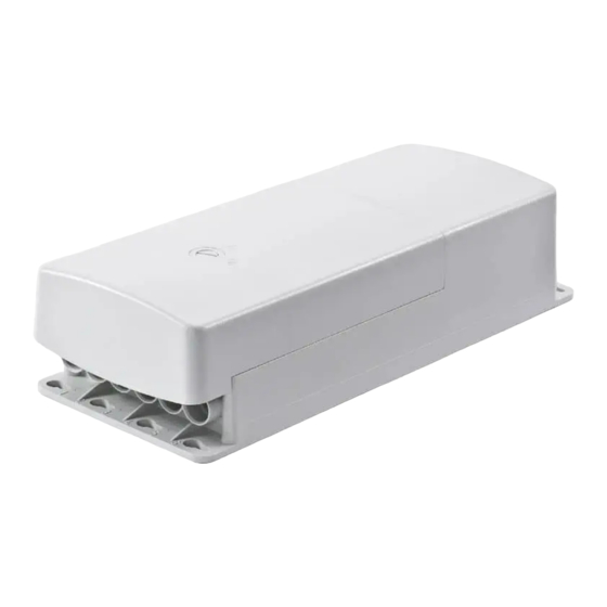
Construction and function This chapter targets all the users of the SCU control unit. It shows its construc- tion and explains its function. Construction The following figures will give you an overview of the SCU control unit, its connections and operating devices. Overall view and connections SCU control unit Fig. -
Page 12: Function
Construction and function 8 Under-floor rechargeable battery 9 Connection for operating elements (sockets 1 to 6) 10 Not occupied (sockets 15, 16) 11 Not occupied (socket 14) 12 Optional rechargeable battery connection (socket 13) 13 Operational voltage indicator (not visible on this image) 14 Communication interface (socket 12) 15 Operational earthing bolt (not visible on this image) 16 Mains connection or connection for source of DC voltage (socket 11) - Page 13 Construction and function Functional principles The principle of functioning of the SCU control unit is based on controlling a maximum of six connected actuator units. The functions present in the control program are actuated by means of manual switches or other operating devices. The SCU control unit is configured by the manufacturer.
-
Page 14: Options And Accessories
Construction and function Options and accessories Options Options can be recognized from the type designation on the type plate. The SCU control unit may be fitted with a battery connection (refer to item 12, Fig. 3-1, Battery connection page 11) or a pre-installed under-floor battery. The unused battery connection is equipped with a sealing stopper by the factory. - Page 15 Construction and function control unit it is only permitted to use original SKF mains cables with the label ZKA-160xxx-xxxx. The connection cable is provided for the DC version.
-
Page 16: Normal Operation
Normal operation This chapter is directed at the user groups operator and operating authority. It contains all the information that is required for the safe and problem-free use of the SCU control unit in normal operation. In normal operation the SCU control unit analyses signals from one operating device in order to actuate the printing or stroke movements with the appropriate actuator. -
Page 17: Scu Control Unit Powering On
Normal operation SCU control unit powering on WARNING Warning regarding electrical shock owing to damaged plugs or damaged network cables. Never touch a damaged network plug or a damaged network cable when the SCU control unit is running, since the SCU control unit are supplied 120 VAC or 230 VAC. -
Page 18: Operating Processes
Normal operation Operating processes Process: Move drives synchronously Responsabilty: Operator Requirements: Parameterize SCU control unit appropriately Drives of the same type Establish preconditions for operation 1 Control several drives synchronously using the SCU control unit operating unit. Please note: If the drives are not of the same type the synchronous movement is not guaranteed. - Page 19 Normal operation Process: Move to memory positions Responsabilty: Operator Requirements: Suitable operating device 1 Press the relevant memory button until all connected and initialized drives are at the saved position. Please note: Drives that reach the correct stroke measurement stop independently. Please note: At high loads for several drives the SCU control unit may stop as a result of the high total power.
-
Page 20: Special Operations
Special operations The following chapters are part of the special operations: 5. Installation and Initial Start-Up, page 20 6. Maintenance, Clearing Malfunctions, Repairs, page 26 7. Removing from service, dismantling and disposal, page 31 Installation and initial start-up This chapter is intended for technicians and those doing the further processing. It contains all the information that is required for the erection, connection and commissioning of the SCU control unit. -
Page 21: Installation And Connections
Installation and initial start-up Power supply The SCU control unit only requires electrical energy for operation. Observe the connection values in the appendix of this manual (chapter Device Data, page 33). Installation and connections The erection and alignment of the SCU control unit, as well as the interfaces and connec- tions are shown in the following sections. - Page 22 Installation and initial start-up Process: Connect the operating device(s) 1 Connect the HD15 plug of the operating device carefully and in the correct position to the corresponding socket of the SCU control unit(see item 3 in Fig. 3-1, page 11). 2 Check that you have used the correct connection socket.
- Page 23 Installation and initial start-up 1 Plug in the plug of the actuator in the corresponding connecting socket of the SCU control unit. Please note: A diagram of the end switch connection is found in the appendix (refer to Plans and diagrams, page 34). Please note: A diode is required to check the line to the end switches (initial defect safety).
-
Page 24: Initial Start-Up
Installation and initial start-up Important: The nut may not be tightened too much because this could cause damage to the housing and the IPX4 protection could no longer be guaranteed. The 1-2 Nm torque should not be exceeded. Installation WARNING Warning regarding electrical shock owing to damaged plugs or damaged network cables. - Page 25 Installation and initial start-up Please note: Ensure that the plugs for the operating units and the end switches are identical. Ensure they are working properly by undertaking the function check. Process: Initialize system Responsabilty: technicians and those doing the further processing 1 Move all drives connected to the SCU control unit to the zero value. Please note: The zero value varies with the drive type. For pressurized drives the zero value is usually at the bottom.
-
Page 26: Maintenance, Clearing Malfunctions, Repairs
Maintenance, clearing malfunctions, repairs This chapter is intended for technicians and those doing the further processing. It contains all the information that is required for the maintenance, troubleshooting and repairs of the SCU control unit. Maintenance The maintenance includes all the work that serves for the upkeep of the functional SCU control unit. -
Page 27: Malfunctions
Malfunctions Malfunctions to the SCU control unit may only be resolved by the manufacturer. For this purpose, the SCU control unit must be shut down and sent to the SKF Actuation System (see section Transport, page 20). In the following sections, you will find hints on how you can recognize, remedy or handle malfunctions. - Page 28 Maintenance, clearing malfunctions, repairs Hypothesis 1-D: SCU control unit is overheated or the supply indicator lamp does not glow. 1 Pull the mains plug of the SCU control unit out of the mains socket and wait for about 30 minutes. 2 Insert the mains plug into the mains socket.
-
Page 29: Repair
Maintenance, clearing malfunctions, repairs Hypothesis 2-B: Rechargeable battery is not inserted correctly. 1 Check whether the cable of the rechargeable battery is correctly inserted into the socket 13 connection. 2* If unsure: Remove the sealing ring to reduce the insertion effort. After the attempt re-assemble the sealing ring. -
Page 30: Removing From Service, Dismantling And Disposal
Removing from service, dismantling and disposal This chapter is intended for technicians and those doing the further processing. It contains all the information that is required for the shutdown, dismantling and disposal of the SCU control unit. Shutting down The SCU control unit must be shut down in the following sequence. 1a AC design: Render the SCU control unit voltage-free (isolate it) by pulling the plug of the control unit from the socket. -
Page 31: Disposal
Removing from service, dismantling and disposal Disposal The SCU control unit must be disposed of in a technically proper manner and in accordance with the local specifications. Please refer in particular to the disposal regulations for the rechargeable batteries. Please find dismantling instructions and shipping requirements in the relevant sections. -
Page 32: Appendix
Appendix This chapter makes it possible for the user to find technical data and directories quickly. Technical data Device data Designation Type SCU 1 Type SCU 4 / 5 Type SCU 8 / 9 SCU control unit: Voltage 24 VDC... -
Page 33: Plans And Diagrams
Appendix Operating data Designation Type SCU 1 Type SCU 4 / 5 Type SCU 8 / 9 Duration of powering on: Intermittent 1 min / 9 min 1 min / 9 min 1 min / 9 min short-term operation 2 min... - Page 34 Appendix Connection diagram for optional external limit switches Single fault safe wiring requires diodes in series to the switches. NC contacts have to be used to stop a movement; NO contacts are used to start movements. Switch connection data: 50 VDC min., 100 mA min. (eff. switching current approx. 10 mA) Up to 6 connections with DIN8 plugs And 2 hall-sensors Option...
-
Page 35: Standards Applied
Appendix Standards applied Fig. 8-3 Declaration of manufacturer page 1... - Page 36 Appendix Fig. 8-4 Declaration of manufacturer page 2 For further information, please contact the manufacturer (see Manufacturer address, page 6).
- Page 37 Index Ambient conditions ....................33 Atmospheric humidity ...................33 Authorized Use ......................7 Battery connection ....................14 Battery package ....................14 Connect operating device ..................22 Connect the actuator unit ..................22 Connections ......................11 Contact address ......................6 DC voltage source ....................13 Declaration of manufacturer ................35 Equipment Data .....................32 Error tolerance period ...................13 Failsafe safety ......................13 Fault rectification ....................27...
- Page 38 Index Safety protective cover Function .................13 Software data label ....................11 Supply schedule .....................20 Technician .......................8 Temperature range ....................33 Transport .........................20 Unauthorized Use ....................7 Under-floor rechargeable battery ...............14 User groups ......................8...
Need help?
Do you have a question about the SCU 1 and is the answer not in the manual?
Questions and answers