Table of Contents

Related Manuals for SKF CMPT DCL


Summary of Contents for SKF CMPT DCL
- Page 1 SKF alarm and display module CMPT DCL Part No. 32163200 Revision D Instruction Manual Copyright © 2014 by SKF Group All rights reserved. Aurorum 30, 977 75 Luleå Sweden Telephone: +46 (0) 31 337 10 00, Fax: +46 (0) 920 134 40...
- Page 2 TSG-Americas@skf.com for customers in North America, South America and Asia. Telephone: +1 800 523 7514 Telephone in Latin America: +55 11 4448 8620 Visit us at our web site www.skf.com/cm ® SKF is a registered trademark of the SKF Group...
-
Page 3: Table Of Contents
Alarm Limit Setting and Alarm Options ....................8 - 17 Completed Configuration and Connection to CMPT CTU ....................8 - 17 Default Configuration when DCL is part of an SKF enclosure ....................8 - 17 Connections with Relay Contacts 9 - 18 Optional Configurations ....................9 - 18... -
Page 4: Description
The CMPT DCL must otherwise be properly installed and configured by the user. Important: Please read this Instruction Manual and the cautionary notes thoroughly. The SKF CMPT DCL is a digital alarm and display module. It is part of a machinery ·... - Page 5 Description Two CMPT DCL modules are needed for stand-alone monitoring of an SKF CMPT · CTU vibration transmitter (one each for vibration and temperature). One CMPT CTU and two DCL modules together are a user-friendly fault detection system of machinery vibration and temperature.
-
Page 6: Features
Front panel user configurable · Input type Display scaling Alarm function Analog output scaling No need for voltmeter and screw driver to set alarm function · 35 mm DIN rail mounted · SKF alarm and display module CMPT DCL Instruction Manual, Revision D... -
Page 7: Specifications
(0.008 inch to 0.03 inch) Mounting: 35 mm DIN-rail type EN50022 Dimensions (W x H x D): 22,5 x 75 x 100 mm (0.89 x 2.95 x 3.94 inches) Approval SKF alarm and display module CMPT DCL Instruction Manual, Revision D... -
Page 8: Dimensions/Front Panel
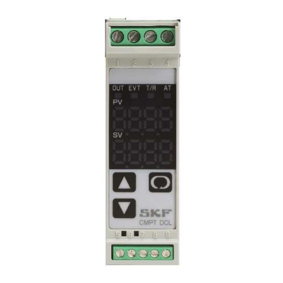
· the upper row displays the Present Value (PV). The PV is the value received from the input device (CMPT DCL, either vibration or temperature). The upper row of digital characters will display the Present Value (PV) from the CMPT DCL transmitter when in the normal operating (default) state. -
Page 9: Caution
• The CMPT DCL is powered by 24 V DC. Do not apply higher voltage. • Do not connect the sensor input (DC voltage) to the CMPT DCL (terminals 5, 6 and 7) until after the unit is powered and the input type is configured. See sections "Configuration"... -
Page 10: Wiring Connections
Wiring Connections Wiring Connections The electrical connections and terminals of the CMPT DCL are listed below. The same figure is also applied to the side of each module. It is recommended to use 1,5 mm (AWG 18 gauge) wire with the DCL. -
Page 11: Configuration
Configuration Configuration The CMPT DCL is configured by SKF when supplied assembled as part of an SKF CMPT enclosure. See Section “Default configuration when DCL is part of an SKF enclosure” for the default settings. The DCL must be configured by the user if supplied as a separate component (i.e. part of a CMPT 1CM type kit). - Page 12 Mode Key (Key 9). The Keys (Keys 7 and 8) are used to set a parameter or value. The settings for the CMPT DCL to monitor the CMPT CTU are defined in the section “Configuration for CMPT CTU vibration and temperature transmitter”...
-
Page 13: Configuration For Cmpt Ctu Vibration And Temperature Transmitter
Caution – Damage can result. Do not connect the CMPT CTU wiring or any other DC input voltage to the CMPT DCL terminals 5 and 6 until after the unit is configured. Damage to the CMPT DCL or CMPT CTU can result. - Page 14 No Change (Change only if other than 20 mA high is desired) Out Low limit setting No change (Change only if other than 0 mA low is desired) SKF alarm and display module CMPT DCL 8-14 Instruction Manual, Revision D...
- Page 15 Controller/Converter function selection Converter function The configuration in Auxiliary Function Setting Mode 2 is complete. See Section " Default Configuration when DCL is part of an SKF enclosure" for completion of installation. IMPORTANT NOTE : CHANGING THE CONFIGURATION IN AUXILIARY FUNCTION MODE SETTING 2 WILL CHANGE THE ALARM LEVEL SETTING MADE IN SUB-SETTING MODE.
-
Page 16: Alarm Limit Setting And Alarm Options
Loop break alarm span setting No change (Not applicable) Sub-setting mode programming is complete. If the High-Low or High Range alarm setting modes are desires, contact SKF for Instructions. IMPORTANT NOTE: CHANGING THE CONFIGURATION IN AUXILIARY FUNCTION MODE SETTING 2 WILL CHANGE THE ALARM LEVEL SETTING MADE IN SUB-SETTING MODE. -
Page 17: Completed Configuration And Connection To Cmpt Ctu
(DCL terminals 3 and 4) is proportional to the full scale set for either vibration or temperature. Default Configuration when DCL is part of an SKF enclosure The CMPT DCL is initially configured by SKF when included as part of an assembled enclosure. The DCL, for vibration or temperature is configured as follows: Vibration... -
Page 18: Optional Configurations
Optional Configurations Optional Configurations The CMPT DCL can optionally be configured to prevent changes to the configuration and to dampen the changes in display and output source values. NOTE: When the Alarm HOLD function selection is set to HOLD (latching), the 24 V DC supply to the DCL must be interrupted to reset the relay. -
Page 19: Appendix
The CMPT DCL has many features that can be configured to enhance the monitoring from the CMPT DCL and also for thermocouples and RTDs. This basic DCL model has some intrinsic features that are not implemented within SKF Copperhead fault detection (controller function, heater burnout, communication protocol, etc.). - Page 20 • When Alarm and Heater burnout alarm are applied together, they utilize common output terminals. • Setting range: 0 to 200 minutes Loop break alarm span setting NOT APPLICABLE SKF alarm and display module CMPT DCL 10-20 Instruction Manual, Revision D...
- Page 21 • Selects the stop bit. • Not available when the option C5 is not added or when Shinko protocol is selected during Communication protocol selection • Setting range: 1 or 2 SKF alarm and display module CMPT DCL 10-21 Instruction Manual, Revision D...
- Page 22 • Selects a sensor type and temperature unit from thermocouple (10 types), RTD (2 types), DC current (2 types) and DC voltage (4 types). • CAUTION - Disconnect the DC voltage input from the CMPT DCL prior to changing input configuration. The input circuit can be damaged if input type is changed while the input is connected.
- Page 23 Low limit alarm: High limit alarm with standby: High/Low limits alarm: Low limit alarm with standby: High/Low limit range alarm: High/Low limits alarm with standby: Alarm action Energized/Deenergized Energized SKF alarm and display module CMPT DCL 10-23 Instruction Manual, Revision D...
- Page 24 • Control desired value adds SVTC bias value to the value received by the SVTC command. • Available only when the option C5 is added. Output status selection when input abnormal Output OFF SKF alarm and display module CMPT DCL 10-24 Instruction Manual, Revision D...
- Page 25 0 to 1V DC –1999 to 9999: 0 to 5V DC –1999 to 9999: 1 to 5V DC –1999 to 9999: 0 to 10V DC –1999 to 9999: SKF alarm and display module CMPT DCL 10-25 Instruction Manual, Revision D...
- Page 26 Character indications: High limit alarm with standby: Low limit alarm with standby: High/Low limits alarm with standby: SKF alarm and display module CMPT DCL 10-26 Instruction Manual, Revision D...
- Page 27 This page intentionally left blank...
Need help?
Do you have a question about the CMPT DCL and is the answer not in the manual?
Questions and answers