SKF LINCOLN 85307 Operating Instructions Manual
Electronic lubrication control unit
Hide thumbs
Also See for LINCOLN 85307:
- Installation instructions manual (24 pages) ,
- Installation instructions manual (32 pages) ,
- Operating instructions manual (36 pages)

Related Manuals for SKF LINCOLN 85307


Summary of Contents for SKF LINCOLN 85307
- Page 1 Operating instructions Electronic lubrication control unit Model 85307; single-line system Date of issue August 2020 Form number 404773 Version...
-
Page 2: Table Of Contents
Contents Description............. . Features . -
Page 3: Description
Description Features Lubrication controller 85307 is a universal • Runs progressive, single-line and electronic control unit compatible with dual-line lubrication systems. dual-line, single-line and progressive • Timing intervals from 5 seconds to lubrication systems. Provides flexibility and 24 hours. control over traditional single-line systems. •... -
Page 4: Safety
Safety Explanation of signal WARNING words for safety • Never weld on machine while main Read and carefully observe operating switch of machine is on. Ensure main instructions before unpacking and operating switch is off and correctly tagged. equipment. Equipment must be operated, Welding on machine can cause maintained and repaired exclusively by serious damage to controller. -
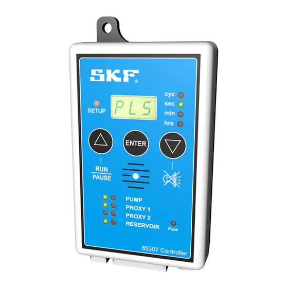
Page 5: Keypad Layout
Fig. 1 Keypad layout Item Description Enter button Run/pause buttton Setup indicator Mounting bracket LED display Cycle indicator Second indicator Minute indicator Hour indicator Select value down or silent buzzer Blown fuse indicator Fuse holder, 8 A Power positive/negative Ignition input/aux power output positive Sensor 1 positive/negative Sensor 2 positive/negative External lamp... -
Page 6: Led Code Descriptions
LED code descriptions Fig. 2 SLS = single-line system SETUP Fig. 3 PLS = progressive-line system SETUP Fig. 4 DLS = dual-line system SETUP Fig. 5 n – 0 = normally open (sensors) SETUP Fig. 6 n – C = normally closed (sensors) SETUP... - Page 7 Fig. 7 L – S = external lamp steady (continued supply) SETUP Fig. 8 L – F = external lamp flashing (pulsed supply) SETUP Fig. 9 nFE = non-fatal error (pump continues on low level fault) SETUP Fig. 10 r = run time in cycles SETUP Fig.
- Page 8 LED code descriptions Fig. 12 F = fault time in seconds, minutes or hours SETUP Fig. 13 U = vent time in seconds, minutes or hours SETUP Fig. 14 rCC = run cycle counter SETUP Fig. 15 YES = confirms program changes SETUP Fig.
- Page 9 Fig. 17 t = time out or dwell time for sensors SETUP Fig. 18 FE = fatal errors (pump stops on Low Level Fault) SETUP Fig. 19 nO = do not select selection SETUP Fig. 20 r = run time in seconds, minutes or hours SETUP Fig.
-
Page 10: Setup Mode
Setup mode Single-line system using pressure switch Fig. 22 SETUP SETUP SETUP ENTER ENTER ENTER PAUSE PAUSE PAUSE PUMP PUMP PUMP PROXY 1 PROXY 1 PROXY 1 PROXY 2 PROXY 2 PROXY 2 RESERVOIR RESERVOIR RESERVOIR Fuse Fuse Fuse 85307 Controller 85307 Controller 85307 Controller 8Amp... - Page 11 Fig. 23 STEP 5 5 P (pause) appears in display. Press Δ to change time (Fig. 23 A). 6 Press ENTER to confirm pause time. LED changes from seconds to minutes to hours. Display indicates In example, pause time of 4 hours is confirmed (Fig. 23 B). amount of pause time when function is applied.
- Page 12 Fig. 24 SETUP SETUP ENTER ENTER PAUSE PAUSE PUMP PUMP PROXY 1 PROXY 1 PROXY 2 PROXY 2 RESERVOIR RESERVOIR Fuse Fuse 85307 Controller 85307 Controller 8Amp 8Amp 7 Run (r) time defaults to cycles. Display shows either 99 cycles or 9 t (time out) displays.
- Page 13 Fig. 25 SETUP SETUP ENTER ENTER PAUSE PAUSE PUMP PUMP PROXY 1 PROXY 1 PROXY 2 PROXY 2 RESERVOIR RESERVOIR Fuse Fuse 85307 Controller 85307 Controller 8Amp 8Amp 11 n-O (normally open) displays indicating whether pressure switch 13 nO (do not select) displays. Green LED on PROXY 2 illuminates. is normally open or normally closed.
- Page 14 Fig. 26 SETUP SETUP ENTER ENTER PAUSE PAUSE PUMP PUMP PROXY 1 PROXY 1 PROXY 2 PROXY 2 RESERVOIR RESERVOIR Fuse Fuse 85307 Controller 85307 Controller 8Amp 8Amp 17 U (vent) displays time in seconds, minutes or hours. Indicates time 19 nO displays.
- Page 15 Fig. 27 SETUP SETUP ENTER ENTER PAUSE PAUSE PUMP PUMP PROXY 1 PROXY 1 PROXY 2 PROXY 2 RESERVOIR RESERVOIR Fuse Fuse 85307 Controller 85307 Controller 8Amp 8Amp 23 n-O (normally open) displays indicating whether sensor is 25 FE (fatal error) or nFE (nonfatal error) appears in display. normally open or normally closed.
- Page 16 Fig. 28 SETUP SETUP ENTER ENTER PAUSE PAUSE PUMP PUMP PROXY 1 PROXY 1 PROXY 2 PROXY 2 RESERVOIR Fuse RESERVOIR Fuse 85307 Controller 85307 Controller 8Amp 8Amp 27 L - F (lamp flashing) displays. This option is used with external 29 tSt (test mode) appears in display.
-
Page 17: Run Mode
Run mode Fig. 29 Unit proceeds in run (r) mode after power is terminated on unit and then switched on again. All devices selected are displayed (Fig. 29). SETUP ENTER NOTE After each cycle received, amount decreases by one until all cycles have been received. -
Page 18: Running System (Pump Pause)
Running system (pump pause) Fig. 31 Controller enters pause (P) time when required run time is reached. Pause time counts down from original setup time to zero and then resumes run time (Fig. 31). Green LED is steady next to PUMP indicating pump is on but not turning while in pause mode. -
Page 19: Wiring Of Pump With Single-Line System Using Pressure Switch
Diagram 1 Wiring of pump with single-line system using pressure switch Item Description Motor Power switch Power supply Microswitch External warning lamp Low level sensor Top row represents front of controller. Bottom row represents back of controller. NOTE: If motor amp draw exceeds the maximum specification (Table 1, page 3), solenoid relay switch (69897S) must be used. Refer to († Diagram 2, page 20). -
Page 20: Wiring Of Pump With Solenoid Relay Switch
Diagram 2 Wiring of pump with solenoid relay switch 12 V 24 V Item Description Fuse, 7.5 A Solenoid relay switch Motor Vent valve solenoid (NO) Power supply, 12 or 24 V Top row represents front of controller. Bottom row represents back of controller. -
Page 21: Fault Indications
Fig. 33 Fault indications Item Description Press RUN/PAUSE to reset faults. Fault indication – counts up from seconds to minutes to hours indicating how long fault has been active. Press ∇ button to silence buzzer. Blown fuse indication – replace with 8 A fuse. - Page 22 This page left intentionally blank.
- Page 23 This page left intentionally blank.
-
Page 24: Warranty
® SKF and Lincoln are registered trademarks of the SKF Group. © SKF Group 2020 The contents of this publication are the copyright of the publisher and may not be reproduced (even extracts) unless prior written permission is granted. Every care has been taken to ensure the accuracy of the information contained in this publication but no liability can be accepted for any loss or damage whether direct, indirect or consequential arising out of the use of the information contained herein.
Need help?
Do you have a question about the LINCOLN 85307 and is the answer not in the manual?
Questions and answers