
Related Manuals for SKF SGA-011


Summary of Contents for SKF SGA-011
- Page 1 Assembly Instructions SGA AND SG DOSER GROUP Date: 17.3.2023 SGA_SG_DOSERS_EN Document No.: Version: 5C Read this manual before in- stalling or commissioning the product and keep it at hand for later reference.
-
Page 2: Table Of Contents
TABLE OF CONTENTS 1 GENERAL ........................1 2 MAINTENANCE ......................1 3 SKF SAFETY INSTRUCTIONS ..................2 3.1 Safety instructions for the operator .................. 2 3.2 Safety instructions for maintenance, inspection and installation ..........2 3.3 Warranty and liability ....................3 4 GENERAL DESCRIPTION .................... -
Page 3: General
This manual is copyright protected. Copying or distributing the document or parts of it with IT or data transfer equipment or to networks without Oy SKF AB Muurame’s express permission is prohibited. Oy SKF Ab Muurame reserves the right to make changes to the content and technical specifications in this manual. -
Page 4: Skf Safety Instructions
3 SKF SAFETY INSTRUCTIONS This operating and service manual contains basic information which must be observed when installing, operat- ing and maintaining the unit. It is necessary for the installer and operator to read these instructions before in- stallation and commissioning. Ensure that these instructions are always accessible to operating personnel. -
Page 5: Warranty And Liability
The relevant regulations in the country must be observed with regard to water pollu- tion and oil disposal. 3.3 Warranty and liability Oy SKF Ab Muurame will not assume any liability, nor will the warranty provided for the product cover any loss in the following cases: •... -
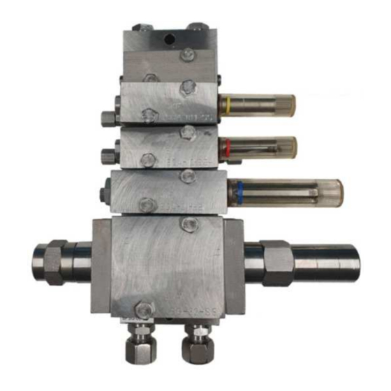
Page 6: General Description
4 GENERAL DESCRIPTION A doser group consist of a base plate (pos. 1) and one or more dosers attached to it (pos. 2). The base plate divides the lubricant to the dosers, which feed the preset amount of lubricant to the lubrication points. 5 DESIGN, SG DOSERS The man components of the doser are the body (2), double-seal piston (3), pilot valve (5), adjustment screw (6) and indicator (7). - Page 7 The indicator and adjustments in an SGA-xxx-WI -type doser are different from standard SG2 -type doser. The indicator has no plastic cover and adjustments are made with adjusting plugs of varying sizes (pos. 9). The indicator and adjustments in an SGA-xxx-NI -type doser are different from standard SG2 -type doser. The indicator is replaced with a plug (pos.
-
Page 8: Operation
6 OPERATION 6.1 Dosers with two outlets Dosers with two outlets alternate dosing between opposite outlet connections between lubrication cycles. The pressure in the line increases during pressurization and the doser pilot valve moves to its extreme posi- tion, whereupon the lubricant moves the dosing piston. When the dosing piston moves, it pushes the lubricant through the base plate check valve to the lubrication pipe or lubrication hose and further to the lubrication point. -
Page 9: Adjustments
The doser with two outlets feeds the lubricant to two different lubrication points. This has been taken into account in the adjustment tables. Table 1. Drawing numbers for adjustment values Doser types (ZN, SS) Drawing number SGA-011, SGA-012 460120 SGA-11, SGA-12 460122 SGA-21, SGA-22 460123... - Page 10 Adjustment of SGA dosers Remove the protective plastic cap. Make sure that the indicator is inside the doser body. WARNING! The SGA doser is damaged if the adjustment screw is adjusted against the indi- cator. Twist the adjustment screw into the basic position where it touches the indicator lightly. Check the adjustment value table for the correct number of adjustment screw turns for the required lubri- cant dose.
- Page 11 Adjustment plugs SGA-01/1 Adjustment plugs SGA-2x GREASE DENSITY 0.88 g/cm³ SGA 01/1 DOSER DOSAGE g/series ±5 % SGA-012-ZN-WI SGA-011-ZN-WI SGA-12-ZN-WI SGA-011-ZN-WI NAME 12387520 12387470 12387620 12387570 PLUG SGA-01/1 1.41 2.82 ADJUSTMENT PLUG-3 1.06 2.12 ADJUSTMENT PLUG-2 ADJUSTMENT PLUG-1 0.35 SGA 2 DOSER DOSAGE g/series ±5 %...
-
Page 12: Technical Specifications
(2-12 pcs), lubrication piping outlets, female thread R 1/8” or NPT 1/8” 8.3 Legend Table 3. Doser designation SGA-xxy-zz-ww Abbreviation Description Lubrication system type: SKF DuoFlex small doser (sizes 01, 1 and 2) no symbol small doser (sizes 3, 4 and 5) doser size 01 doser size 1 doser size 2... - Page 13 Base plate material, acid-proof steel, AISI-316 no symbol connections, BSP G threads Connections, NPT threads Example: BPSG-03-AL Base plate material, aluminium Base plate size, 3 doser slots Lubrication system type, SKF Dual line Base Plate Connections: BSP G threads 11 (16)
-
Page 14: Base Plate Dimensioning And Codes
8.4 Base plate dimensioning and codes Table 5. Base plate dimensioning Model Number BPSG-01-AL 12383250 BPSG-02-AL 12383300 BPSG-03-AL 12383350 BPSG-04-AL 12383400 BPSG-05-AL 12383450 BPSG-06-AL 12383500 BPSG-01-SS 12384300 BPSG-02-SS 12384350 BPSG-03-SS 12384400 BPSG-04-SS 12384450 BPSG-05-SS 12384500 BPSG-06-SS 12384550 12 (16) - Page 15 Table 7. U model dimensions Model Number 46 (1 ") 60 (2 ") BPSG-01-AL-U 12384000 78 (3 ") 92 (3 ") BPSG-02-AL-U 12384050 110 (4 ") 124 (4 ") BPSG-03-AL-U 12384100 142(5 ") 156 (6 ") BPSG-04-AL-U 12384150 174 (6 ") 188 (7 ")
- Page 16 Table 8. B model dimensioning Model Number BPSG-01-AL-B 12383550 BPSG-02-AL-B 12383560 BPSG-03-AL-B 12383570 BPSG-04-AL-B 12383580 BPSG-05-AL-B 12383590 BPSG-06-AL-B 12383600 14 (16)
-
Page 17: Removing From Service
Oy SKF AB will receive products it has delivered and take care of their appropriate disposal. Oy SKF AB has the right to charge for expenses that are not related to disposal and recycling. -
Page 18: Repair Kits
11.3 Other spare parts and dimensional drawings See SGA and SG doser group spare parts (drawing 461505). See WI dosers SGA-011, SGA-012, SGA-11 & SGA-12 dimensions and spare parts (drawing 361261) See WI dosers SGA-2 dimensions and spare parts (drawing 361344) See NI dosers SGA-011, SGA-012, SGA-11 &... - Page 40 DETAIL DRAW MATERIAL DESCRIPTION 3,34 6,68 (WEIGHT KG) ITEM SPECIFICATION OF PART 2,15 4,29 DESIGNED DRAWN FUTURE DRG PREVIOUS DRG DOSERS SGA-2-ZN-NI 0,98 1,97 DATE PROJECT Oy SKF Ab DIMENSIONS, ADJUSTMENT, 2.7.2008 SPARE PARTS MUURAME SCALE DRAWING NUMBER 361462 FINLAND...
Need help?
Do you have a question about the SGA-011 and is the answer not in the manual?
Questions and answers