Advertisement
Advertisement
Table of Contents

Related Manuals for Fnirsi DSO510


Summary of Contents for Fnirsi DSO510
- Page 1 DSO510 数 字 示 波 器 使 用 说 明 书 Digital Oscilloscope Instruction Manual 示波器...
- Page 3 目 录...
- Page 4 CATALOG...
- Page 5 用户须知 ●本手册详细介绍了产品的使用方法、 注意事项以及相关事项, 在使用产品之前, 请详细阅 读手册, 以便发挥产品的最佳性能。 ●不要在易燃、 易爆的环境中使用仪器。 ●仪器更换的废旧电池和报废的仪器不可与生活垃圾一同处理请按国家或者当地的相关 法律规定处理。 ●当仪器出现任何质量问题或者对使用仪器有疑问时, 可联系 “菲尼瑞斯-FNIRSI” 在线客 服或厂家, 我们将在第一时间为您解决。 一、 产品简介 “DSO-510” 是我司推出的一款高实用性,高性价比,针对于维修行业和研发教育行业人群的 高性价比手持示波器。 该示波器具有48MS/s的实时采样率、 10MHz带宽、 完整的触发功能 (单次,正常,自动)。 对于周期模拟信号及非周期的数字信号都能运用自如,最高可测量 ±400V的电压配备高效一键AUTO,无需繁琐调节即可显示被测波形。 另外还带有多种函数 信号发生器(50KHz)。 搭载2.8英寸320*240分辨率的高清液晶屏,内置1000mAh高品质锂电 池,充满电后可连续使用4小时左右。...
- Page 6 二、 面板介绍 信号发生器输出端口 校准方波 信号输入探头 (MCX) 接口 拨轮按键 (左、 OK、 右) AUTO按键 MODE按键 复位孔 充电指示灯 2.8inch 上按键 (充电中红灯, 充满绿灯) 下按键 TYPE-C 充电接口 RUN按键 (5V/1A) 开关按键...
- Page 7 三、 按键功能 按键 操作 主界面 示波器 信号发生器 设置 控制各参数 降低音量/ 左拨动 向上选择 数值位选择 功能调节选择 亮度 进入当前设 进入界面 进入/退出数值 短按 置/确定当 前设置参数 长按 返回主界面 控制各参数 提高音量/ 右拨动 向下选择 数值位选择 功能调节选择 亮度...
- Page 8 按键 操作 主界面 示波器 信号发生器 设置 自动测量 短按 长按 自动校正 切换测量模式 短按 返回 返回 长按 参数设置界面 短按 向上选择/调节参数 向下选择/调节参数 短按 短按 运行/暂停波形 开启/关闭输出 长按 保存波形 开/关机 短按...
- Page 9 示波器参数设置界面按键说明 按键 操作 波形 参数 余晖 图片 切换参数 打开/关闭参数 短按 打开图片 向左查看图片 左拨动 向左选择 右拨动 向右查看图片 向右选择 短按 向上选择(参数界面可选择至上一列) 短按 向下选择(参数界面可选择至下一列) 进入/退出参数设置界面 长按 *示波器参数设置界面见09页...
- Page 10 四、 参数指标 采样率 48MS/s 信号发生器 0-50KHz 频率 带宽 占空比 0-100% (矩形波和锯齿波) 垂直灵敏度 10mV/Div-10V/Div 幅值 0.1-3.0V 时基范围 50ns-20S 正弦波, 矩形波, 锯齿波, X1:±40V (Vpp:80V) 电压范围 半波, 全波, 正阶梯波, 反阶 X10: ±400V (Vpp :800V) 波形 梯波, 指数升, 指数降, 直流信号, 多音频, 辛克 触发方式 自动/常规/单次 脉冲, 洛伦茨波...
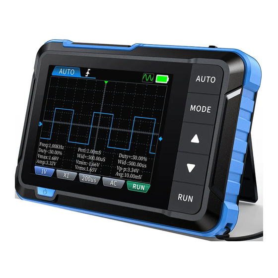
- Page 11 五、 屏幕指示 5.1 示波器界面 H=�mS 频率: ���.��Hz 正占空比: ��.��% 峰峰值: �.��mV 示波器 ��mV 自动 X� 主界面 示波器界面...
- Page 12 ①垂直单位: 表示垂直方向一大格代表的电压 ②触发模式指示图标: Auto表示自动触发,Single表示单次触发, Normal表示正常触发 ③探头比例:这个必须和探头手柄上的1X/10X开关设置保持一致,若探头是1X档,那么示波 器也要设置为1X档,1X测量±40V电压,10X测测量±400V电压 ④输入耦合方式指示图标,AC表示交流耦合,DC表示直流耦合 ⑤触发电压指示图标 ⑥触发位置指示图标 ⑦基线指示图标,此图标指示位置表示当前位置为 0V 电压 ⑧水平时基,表示水平方向一大格代表的时间长度 ⑨触运行暂停指示图标,RUN表示运行,STOP表示暂停 ⑩触发边沿指示图标 ⑪ :左右控制时基, 上下控制通道的垂直灵敏度; :左右控制水平触发移动, 上下控制通道波形上下移动; :左右控制水平触发移动, 上下控制触发电平移动 *按 控制切换 ⑫电池电量...
- Page 13 5.2 示波器参数设置界面 H=�mS H=�mS 波形 参数 余晖 图片 长按 耦合类型: MODE X� X�� 探头比例: 触发模式: 正常 自动 单次 触发沿: 频率: ���.��Hz 正占空比: ��.��% 峰峰值: �.��mV 频率: ���.��Hz 正占空比: ��.��% 峰峰值: �.��mV ��mV 自动 X� ��mV 自动 X� 示波器界面 示波器参数设置界面 ①波形: 设置耦合类型、 探头比例、 触发模式、 触发沿 ②参数:...
- Page 14 5.3 信号发生器界面 信号发生器 正弦波 矩形波 锯齿波 �� ��� 频 率 半波 ��� 占空比 全波 信号发生器 正阶梯波 幅 值 �.� 信号发生器界面 主界面 ①波形的选择 ②波形的显示 ③频率设置 ④占空比设置 ⑤幅值设置 ⑥信号发生器的开启与关闭 (关闭变红) ⑦电池电量...
- Page 15 5.4 设置界面 1、 设置单项选择: 系统设置 语言、 声光设置、 开机启动、 主题设置、 自动 语 言 关机、 关于、 恢复出厂设置 中文 声光设置 2、 具体设置详情: 开机启动 ①语言: 中文,English 频 率 English 主题设置 ②声光设置: 亮度: 25~100; 声音: 0~10 ③开机启动: 关、 示波器、 信号发生器。 该设 自动关机 置用于设置开机自动启动哪个功能模块 USB共享 ④主题设置: 蓝色、 黄色。 系统设置...
- Page 16 六、 固件升级 ①在关机的情况下, 先按紧 后, 然后按住 。 ②使用Type-C线连接板子上的Type-C口至电脑端,此时电脑会弹出一个名为 “IAP” 的U盘。 ③将固件拉入到U盘里, 如果固件升级完成, 会自动跳到APP。 注意 ·固件升级只支持在电脑 Windows 10及以上系统使用 ·升级过程中需一直按紧开机键, 直至文件传输完成 七、 注意事项 ●收到设备后, 请在充满电后使用。 ●使用示波器的时候要注意档位的选择, 示波器的档位跟探头的档位要保持一致。 ●测量高压时, 禁止碰触示波器任何金属部位, 以免造成触电风险。 ●尽量不要在充电时, 进行高压测试。...
- Page 17 ●校准时, 需要拔掉BNC探头, 或者探头正负极短接。 ●USB固件升级仅支持WIN10及以上, 禁止拖入除发布固件以外的文件, 否则极可能造成 不可以恢复之后果。 ●请使用说明书规格范围内的电压进行充电。 八、 生产信息 产品名称: DSO510迷你数字示波器 品牌/型号:FNIRSI/DSO510 服务电话: 0755-28020752 服务邮箱: support@fnirsi.com 商务邮箱: business@fnirsi.com 生产商: 深圳市菲尼瑞斯科技有限公司 地址: 广东省深圳市龙华区大浪街道伟华达工业园C栋西边8楼 网址: www.fnirsi.cn 执行标准: GB/T 15289-2013...
-
Page 18: Notice To Users
●If there are any quality issues with the device or if you have any questions about using the device, please contact “FNIRSI” online customer service and we will solve it for you in the first time. 1、 Product Introduction DSO-153 is a highly practical and cost-effective handheld oscilloscope launched by our company,... -
Page 19: Panel Introduction
2.Panel Introduction Square wave calibration Wheel button (left, OK, right) AUTO button MODE button Reset hole Charging indicator light 2.8inch Up button (charging- red light, fully charged -green light) Down button TYPE-C charging interface (5V/1A) RUN button Power button... -
Page 20: Buttons Functions
3.Buttons Functions Signal Main Setting Button Operation Oscilloscope Generator Menu Control various Decrease Numerical Move to Upward parameters, volume/ position selection the left selection function adjustment brightness selection Enter current settings/Confirm Enter Enter/exit Short current setting press interface numerical values parameters Long Return main menu... - Page 21 Signal Main Setting Button Operation Oscilloscope Generator Menu Automatic Short press measurement Long press Auto calibration Switch Short press Return Return measurement mode Parameter Long press settings interface Short press Upward selection/adjustment of parameters Short press Downward selection/adjustment of parameters Enable/ Short press Run/pause waveform...
- Page 22 Oscilloscope Parameter Settings Interface Buttons Functions Wave- Image Button Operation Parameters Persistence form Switch Turn on/ Short press Open image parameters off parameters Move to View previous Select leftward the left image Move to View next image Select rightward the Right Short press Move upward (in parameter interface, move to the previous column) Short press...
-
Page 23: Product Parameters
4.Product Parameters Signal generator Sampling rate 48MS/s Frequency 0-50KHz Bandwidth 0-100% (rectangular and sawtooth Duty cycle Vertical sensitivity 10mV/Div-10V/Div waves) Amplitude 0.1-3.0V 50ns-20S Time Base Range Sine wave, rectangular wave, sawtooth X1:±40V (Vpp:80V) Voltage range wave, half wave, full wave, step wave, Waveforms anti step wave, exponential rise, X10:±400V (Vpp:800V)... - Page 24 5.Screen Indication 5.1 Oscilloscope Interface H=�mS Osciloscope Freq: ���.��Hz Duty+: ��.��% Vp-p: �.��mV ��mV Auto X� Main Menu Oscilloscope Interface...
- Page 25 ①Vertical unit: represents the voltage represented by a large grid in the vertical direction ②Trigger mode indicator icon, Auto represents automatic triggering, Single represents single triggering, Normal represents normal triggering ③Probe ratio: This must be consistent with the setting of the 1X/10X switch on the probe handle. If the probe is in 1X mode, then the oscilloscope should also be set to 1X mode, where 1X measures 40V voltage and 10X measures 400V voltage ④Input coupling method indicator icon, AC represents AC coupling, DC represents DC coupling...
- Page 26 5.2 Oscilloscope Parameter Settings Interface H=�mS H=�mS Paramet- Persist- Waveform Image ence Long press Coupling: MODE X� X�� Probe: Single Normal Auto Mode: Edge: Freq: ���.��Hz Duty+: ��.��% Vp-p: �.��mV 频率: ���.��Hz 正占空比: ��.��% 峰峰值: �.��mV ��mV Auto X� ��mV Auto X�...
- Page 27 5.3 Signal Generator Interface Signal Generator Sine Wave Square Wave Sawooth Wave Frequen- �� ��� Half-wave Duty Cy- ��� Full Wave Signal Generator Amplitu- Step Wave �.� Signal Generator Interface Main Menu ① Waveforms selection ② Display of waveforms ③ Frequency setting ④...
- Page 28 5.4 Settings Interface 1. Set single item selection: System Settings Language, Sound and light , Startup on boot, Language Theme, Auto Shutdown, USB Sharing, About, Factory Reset 中文 Sound and light 2. Specific settings details: Startup on Boot ①Language: Chinese, English. 频...
-
Page 29: Points For Attention
6.Firmware Update ① In the case of shutting down, press and hold the first and then press button. ② Use a Type-C cable to connect the Type-C port on the board to the computer, and a USB drive named "IAP" will pop up on the computer. ③... - Page 30 By the way, we have created an interesting community, welcome to contact FNiRSl staff to join our community. Shenzhen FNIRSI Technology Co., LTD. Add.: West of Building C , Weida Industrial Park , Dalang Street , Longhua District , Shenzhen , Guangdong , China Tel:...
Need help?
Do you have a question about the DSO510 and is the answer not in the manual?
Questions and answers