
Related Manuals for AVer TR335


Summary of Contents for AVer TR335
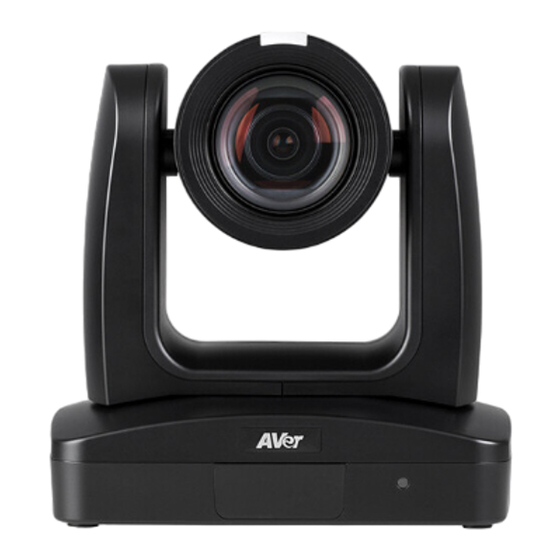
- Page 1 AI Auto Tracking PTZ Camera — — User Manual TR335 / TR335N / TR315 / TR315N / TR325 / TR325N / TR211 / TR311V3...
- Page 2 Federal Communications Commission NOTE: This equipment has been tested and found to comply with the limits for a Class A digital device, pursuant to part 15 of the FCC Rules. These limits are designed to provide reasonable protection against harmful interference when the equipment is operated in a commercial environment.
- Page 3 © 2024 AVer Information Inc. All rights reserved. | June 20, 2024 All rights of this object belong to AVer Information Inc. Reproduced or transmitted in any form or by any means without the prior written permission of AVer Information Inc. is prohibited. All information or specifications are subject to change without prior notice.
- Page 4 WARNING To reduce the risk of fire or electric shock, do not expose this appliance to rain or moisture. Warranty will be void if any unauthorized modifications are done to the product. Do not drop the camera or subject it to physical shock. ...
- Page 5 お客様サポートセンター(固定電話のみ): +81 (0) 120 008 382 Vietnam Branch Office Korea Office 한국 에버 인포메이션 (주) Công ty TNHH AVer Information (Việt Nam) Tầng 5, 596 Nguyễn Đình Chiểu, 서울시 종로구 새문안로 92 (신문로 1 가, 광화문오피시아빌딩) 1831, P.3, Quận 3, 1832 호...
-
Page 6: Table Of Contents
Contents Overview ........................ 4 Package Contents ....................4 Optional Accessories .................... 4 Parts Info ......................5 Dimensions ......................6 Pan and Tilt Angle ....................9 LED Indicators ....................10 Remote Control ....................10 Connection ......................12 Device Connection ..................... 12 PoE Connection.................... - Page 7 Advanced Setting ..................29 System ......................29 Get Started ......................31 Access the Web Interface .................. 31 AVer IPCam Utility ..................31 AVer PTZ Management ................. 33 Web Interface....................... 34 Live View ......................34 Camera Control ..................... 34 Preset ......................35 Camera Settings ....................
- Page 8 CGI Command....................70 Pelco P Command ....................74 Pelco D Command ..................... 75...
-
Page 9: Overview
Overview Package Contents Camera Unit Power Adapter & Remote Control Cable Fixing Plate Power Cord 1/4”-20, L=6.5mm Ceiling Mount Bracket M2 x 4mm M3 x 6mm (x2) Screw (x3) Screw (x2) Screw (x3) DIN8 to D-Sub9 RS-232 In/Out Cable Ties (x4) Drill Template Cable Y Cable... -
Page 10: Parts Info
Parts Info 1. Tally Lamp 4. Kensington Lock 5. PoE+ IEEE 802.3AT 2. IR Sensor 6. RS-232 Port 3. LED Indicator 7. RS-422 Port 8. USB 3.0 Type-B Port 9. Audio In* 10. HDMI Port 11. 3G-SDI (unavailable for model names with H) 12. -
Page 11: Dimensions
Dimensions 80mm 156.5mm 145mm 180mm 161.3mm 145mm 156.5mm 161.3mm 180mm... - Page 12 Ceiling Mount 80mm 104mm 153mm 161.3mm 180mm 200.8mm...
- Page 13 Wall Mount 180mm 161.3mm 206mm 263.2mm...
-
Page 14: Pan And Tilt Angle
Pan and Tilt Angle... -
Page 15: Led Indicators
LED Indicators Status Flashing blue Auto Tracking On Solid blue Normal Flashing red Firmware update Solid orange Standby Flashing orange Start-up Flashing purple Gesture recognition Remote Control Name Function 1. Power Power on or enter standby mode. Open and close the OSD menu during HDMI 2. - Page 16 11. PT Reset Return the pan-tilt position to the center. Invert L/R Pan Direction: Press and hold L/R SET, then press Position 2. 12. L/R SET Reset L/R Pan Direction: Press and hold L/R SET, then press Position 1. 13.
-
Page 17: Connection
Connection Device Connection... -
Page 18: Poe Connection
PoE Connection Connect the camera to the router or switch through the PoE+ port. [Note] Only support IEEE 802.3AT PoE+ standard. Ethernet Cable (Not Included) Router/PoE Switch... -
Page 19: Rs-232 And Rs-422 Connection
RS-232 and RS-422 Connection Connect through the RS-232 or RS-422 for camera control. RS-232... - Page 20 ● RS-232 Port Pin Definition Function Mini DIN9 Signal Description PIN # Type VISCA IN Output Data Terminal Ready Input Data Set Ready Output Transmit Data Input Receiver Data VISCA Output Data Terminal Ready Input Data Set Ready Output Transmit Data Input Receiver Data Input...
- Page 21 ● RS-232 mini DIN9 to mini DIN8 Cable Pin Definition Mini DIN8 Cable Pin Definition Signal...
- Page 22 ● Din8 to D-Sub9 Cable Pin Definition...
- Page 23 ● RS-422 [Notes] Use cat5e splitter for multi-camera connection. RS-422 Pin Cat5e splitter pin assignment: Camera Camera/Joystick Camera/Joystick...
-
Page 24: Audio Input Connection
Audio Input Connection Connect the audio device for audio receiving. [Notes] Line input level: 1Vrms (max.). Mic input level: 50mVrms (max.); Supplied voltage: 2.5V. Microphone Audio Mixer... -
Page 25: Video Output Connection
Video Output Connection HDMI Use the HDMI cable to connect with monitor or TV for video output. 3G-SDI Connect to 3G-SDI monitor for video output. 3G-SDI Cable (Not Included) SDI Monitor [Notes] HDMI and 3G-SDI monitors can be connected to camera and output live video simultaneously. When the HDMI monitor is well connected before the camera is turned on, the OSD menu will be displayed on HDMI monitor as default. -
Page 26: Installation
Installation Cable Fixing Plate Installation 1. Secure the cable fixing plate to the camera with 3 M2 x 4mm screws (included). 3. Use 4 cable ties to secure the cables and cable 2. Plug in cables. fixing plate. -
Page 27: Ceiling Mount Installation
Ceiling Mount Installation 1. Secure the mount bracket on the ceiling. 2. Install the mount bracket on the camera. Screw: 4 screws, M4 x 10mm (Not Included Screw: 2 screws, 1/4"-20 L=6.5mm in the package) (Included in the package) 3. Slide the mount bracket with the camera 4. -
Page 28: Camera Installation
Camera Installation Angle A: less than 30˚ Height B: 2~3m from floor Distance C: longer than 3m away from podium Position: center of classroom Distance between the camera and tracking target (presenter): Optical zoom ratio ability Upper body size Full body size 3~16m... -
Page 29: Set Up The Camera
Set Up the Camera OSD Menu You can use the supplied Remote Control to operate the OSD Menu during HDMI output. Press the button to call out the On-Screen Display (OSD) menu and use the ▲ , ▼ , , and buttons to operate the OSD menu. -
Page 30: Dhcp
DHCP 1. Press the button on the remote control to call out the OSD menu. 2. Go to Network > DHCP > On. 3. After turning the DHCP on, the user can view IP address in System > Information. -
Page 31: Osd Menu Tree
OSD Menu Tree Camera Set up camera parameters: Exposure Mode, White Balance, Pan Tilt Zoom, Noise Reduction, Saturation, Contrast, Sharpness, Mirror and Flip. Layer Layer Layer Layer Layer Camera Exposure Full Auto Exposure Value -4/-3/-2/-1/0/1/2/3/4 Mode Gain Limit Level 24dB/27dB/30dB/33dB/36dB /39dB/42dB Slow Shutter Off/On... - Page 32 Layer Layer Layer Layer Layer Camera White Balance Auto Indoor Outdoor One push Manual R Gain (0-255) B Gain (0-255) Pan Tilt Zoom Preset Speed 5/25/50/100/ 150/200 Digital Zoom Off/On Digital Zoom x2-x12 Limit Pan/Tilt Slow Off/On Off/Low/ Noise Reduction Medium/High Saturation 0-10...
- Page 33 Supported AVer Cameras: PTC300V2 Series PTC500 PTC330 PTC310 Series PTC115 Series Series Series PTC330UV2 PTC500S PTC330 PTC310 PTC115 TR333V2 TR530 TR331 TR311 TR320 PTC320UNV2 PTC500+ PTC330N PTC310U PTC115+ TR323NV2 TR530+ TR331N TR313 TR320+ PTC320UV2 PTC330U PTC310H TR333 PTC310N TR311N PTC310UN...
-
Page 34: Video Output
Video Output Select video resolution (2160p is only supported on certain models). Layer Layer Layer Video Output Theme Mode Standard/Zoom/Teams/(NDI) Frequency 50Hz/59.94Hz/60Hz Resolution 2160P/30, 2160P/60, 1080P/60, 1080P/30, 1080I/60, 720P/60 Network Set up IP mode – DHCP or Static IP. Layer Layer Layer Network... - Page 35 Status OSD Off/On Language English/繁體中文/日本語/简体中文/한국어/ Tiếng Việt Off/On Tally Disable/Enable Information Model Name/Version/IP Address/MAC/Lens/Mcu Factory Default Off/On Account Default Off/On...
-
Page 36: Get Started
Access the Web Interface To access the web interface of your camera, you can use any of the following software to find its IP address: AVer IPCam Utility AVer PTZ Management Note: The PoE+ port defaults to a static IP address of 192.168.1.168, while the Ethernet port uses DHCP. - Page 37 To access the web interface: 1. Download IPCam Utility from AVer Download Center (https://www.aver.com/download-center) launch the software. 2. Click Search to see available devices on the same local area network (LAN). Note: Make sure your MT300 is connected to the internet.
-
Page 38: Aver Ptz Management
AVer PTZ Management Note: The PTZ Management default username and password is admin/admin. 1. Download PTZ Management from AVer Download Center (https://www.aver.com/download- center) and launch the software. 2. Log in with the PTZ Management default username and password admin/admin. 3. Go to Setup > Add, then click Auto Search to see available devices on the same local area network (LAN). -
Page 39: Web Interface
Web Interface Live View Camera Control Item Description Pan and Tilt Controls Position the camera. Drag the slider to adjust Pan Speed and Tilt Speed. Home Position Move the camera to the Home position. Zoom Zoom in or zoom out the live view and select Zoom Speed. Auto Focus Select Auto Focus and then choose an AF mode: ... -
Page 40: Preset
Continuous AF: Automatically focus continuously. Click to manually focus. Adjust the focus with +- buttons. Manual Focus One Push Focus Click to automatically focus once. Focus Near Limit Set up the nearest focus limit. Digital Zoom Turn digital zoom on or off. Digital Zoom Limit Adjust the digital zoom. -
Page 41: Camera Settings
Camera Settings Exposure Note: Click Default to reset Exposure to factory default settings. Item Description Choose an exposure mode. Exposure Mode Adjust exposure, shutter, iris and gain. Exposure Value Shutter Speed Iris Level Gain Level... -
Page 42: Image Process
Gain Limit Level Turn backlight compensation (BLC), slow shutter, wide dynamic range (WDR) on or off. Slow Shutter Drag the slider to adjust the brightness value. Bright Value Image Process Note: Click Default to reset Image Process to factory default settings. Item Description White Balance... -
Page 43: Video & Audio
Video & Audio Video and Audio Settings Item Description Power Frequency Select 50Hz, 59.94Hz or 60Hz based on your country and region. Video Output Select a resolution to display on your video output device. Resolution Theme Mode Select a video mode based on your output interface. ... - Page 44 HDMI, SDI, IP, NDI* Standard NDI HX3 *To change the sleep mode position, go to System > Sleep to Preset on the web application. Stream Video Output Select a stream resolution on live view from the drop-down list. Bitrate Select a bitrate from the drop-down list. Select a framerate for live stream –...
-
Page 45: Network
Network Item Description Set up the network to DHCP or Static IP. DHCP DHCP: Select On to assign the related IP settings with the camera automatically. Click Confirm to save the settings. Static IP: Select Off to manually enter the IP Address, Netmask, Gateway and DNS. - Page 46 Stream camera live video to a video platform such as YouTube. RTMP Settings 1. Enter the Server URL and Stream Key of the platform. Please refer to the instruction of the platform you use to obtain the server URL and stream key.
- Page 47 3. Paste the IP address and Port value into SRT Settings fields and click Start Stream. Connect Status will change to Connected. OBS (Open Broadcaster Software) 1. Make sure the OBS workstation and your camera are on same network.
- Page 48 3. Click Choose File to select the certificate file, and then click Upload. 4. Turn on HTTPS. SSHD Turn remote debugging from AVer on or off. Select a VISCA port mode. Visca Port Mode After selected, enter Visca Port Number.
-
Page 49: Tracking Settings
Tracking Settings Tracking Modes Overview For details on settings, please refer to their respective chapters. Presenter Mode Frames and follows the presenter on screen. Zone Mode Frames and follows the presenter on screen using up to four presets. When the presenter exits the previous preset, the camera will follow and move to the next preset. -
Page 50: Compare Tracking Modes
Compare Tracking Modes Presenter Mode Zone Mode Hybrid Mode (Presenter +Zone) Use case Performance arts Keynotes, All of the above presentations Perfect for Movements Content Movements and content Available presets Preset 1 Presets 6–9 Presets 10–13 Presenter Presets can have a detection area ... -
Page 51: Tracking Control Panel
Tracking Control Panel Tracking: Turn tracking on or off. Mode: Select a tracking mode to frame and follow the presenter in real time as they move. For details on tracking settings, please refer to respective chapters. Click Track: Presenter Mode uses facial recognition and lets you switch the presenter you want to track. -
Page 52: Presenter Mode
Presenter Mode Presenter Mode frames and follows the presenter on screen, and returns to the tracking point (Preset 1) when no one is on screen. To set up Presenter Mode: 1. Go to Tracking Settings > Presenter. 2. Use pan, tilt and zoom controls to position your camera and click Save to Preset 1 to save the Tracking Point. - Page 53 If no one is on screen, the camera will return to the tracking Tracking Point point (Preset 1). Frame the presenter’s full body or upper body. People Size, Placement, Height Horizontally align the presenter to the left, center or right. ...
- Page 54 To set up Presenter Mode with the remote control: 1. Use directional buttons to position your camera. Press and hold Preset, then press Number button 1 to save the tracking point (Preset 1). 2. Press Auto Tracking ON to turn on Presenter Mode. 3.
-
Page 55: Zone Mode
Zone Mode Zone Mode uses up to 4 presets to frame and follow the presenter on screen. When the presenter exits the previous preset, the camera will follow and move to the next preset. When no one is in the presets, the camera returns to the tracking point (Preset 6 or selected preset). Note: ... - Page 56 4. Use pan, tilt and zoom controls to position your camera and click Save to save that position. A thumbnail will appear in the preview. Repeat these steps for all presets. Note: Define overlapping presets from left to right for a smooth transition. When the presenter exits the previous preset, the camera will follow and move to the next preset.
- Page 57 To set up Zone Mode with the remote control: 1. Use directional buttons to position your camera. Press and hold Preset, then press Number button 6 to save Preset 6. Repeat these steps for Preset 7. Note: Zone Mode has 2 blocks by default. To select more blocks, access the web interface. 2.
-
Page 58: Hybrid Mode
Hybrid Mode Hybrid Mode combines Preseter Mode and Zone Mode, and lets you define a detection area for each preset. Defining a detection area will allow a smoother transition, but ou can also define a preset without one. When the presenter enters the detection area, the camera will move to the corresponding preset. When the presenter leaves the detection area, the camera frames and follows the presenter. - Page 59 5. Then, define presets. Use pan, tilt and zoom controls to position your camera and click Save to save that position. A thumbnail will appear in the preview. Repeat steps 2–5 for all presets. Note: Do not overlap presets. Leave ample room between presets for a smooth transition. ...
- Page 60 When Auto Zoom is turned off, the zoom ratio will be Auto Zoom based on your selected present from the drop-down list. When Auto Tilt is turned off, the tilt angle will be based on your selected present from the drop-down list. Auto Tilt 8.
-
Page 61: Gesture
Gesture Notes: The effective distance is 15 feet at 1X zoom ratio. When a gesture is recognized, the LED indicator will flash purple. To set up gesture control: 1. Turn the Tracking off. 2. Select an option from the Gesture Control drop-down list. Item Description Turn Gesture Control off. - Page 62 Gesture Control List: Gesture Description Auto Tracking enable / Switch Presenter Raise your hand beside your face (with an open hand) for more than 3 seconds to activate the Auto Tracking. Instruct camera to track the person that holds up beside his/her face (only enabled when Auto Tracking is on).
-
Page 63: Ndi
Note: NDI is available for model names with N only. To set up the NDI function: This camera is compatible with NDI | HX3 of NewTek, Inc. To use NDI | HX3, you are required to purchase the license key from the URL of NewTek, Inc. https://www.newtek.com/ndihx/products/upgrade/ To activate the NDI license key: 1. - Page 64 Local Device Name Enter a name that identifies your camera group on the NDI software. The default is AVer. Device Channel (Camera ID) Enter a name that identifies your camera on the NDI software. The default is your model name.
-
Page 65: System
System Item Description To upgrade the firmware: 1. Download the newest firmware from AVer Download Center (https://www.aver.com/Download-Center/professional-ptz- camera) 2. On the web interface, go to System > Upgrade firmware. Upgrade firmware 3. Click Choose File to select the firmware. 4. Click Upgrade. - Page 66 Password: Use 8-32 characters and a combination of uppercase letters, lowercase letters, numbers, and symbols (%+=,-_^/@.~). The password cannot be the same as the username. Language Change the web interface language. Reboot Restart your camera. Set Date/Time Set the camera date and time. Power Schedule Schedule specific times for the camera to reboot or shut down.
- Page 67 Help Improving AVer Opt-in or opt-out of providing anonymous usage data. Camera LED Indicator Brightness Drag the slider to adjust the brightness.
-
Page 68: Audio Integrated
Audio Integrated Item Description Enter the microphone IP you want to connect. Click Start to connect Mic Settings and Stop to disconnect. Back to Preset Select an idle time before the camera goes to your selected preset. Time to trigger Preset Select an idle time for the camera to move to the preset when the microphone detects sound. -
Page 69: Appendix
Appendix VISCA RS-232 Command Table Command Set Command Command Packet Comments CAM_Power 8x 01 04 00 02 FF Power ON/OFF 8x 01 04 00 03 FF CAM_Zoom Stop 8x 01 04 07 00 FF Tele(Variable) 8x 01 04 07 2p FF p=0 (Low) to 7 (High) Wide(Variable) 8x 01 04 07 3p FF... - Page 70 CAM_Exposure 8x 01 04 0E 02 FF Exposure Compensation Amount Setting Compensation Down 8x 01 04 0E 03 FF CAM_Backlight 8x 01 04 33 02 FF Back Light Compensation ON/OFF 8x 01 04 33 03 FF CAM_Preset Reset 8x 01 04 3F 00 pp FF pp: Preset Number 0x00~0xFF 8x 01 04 3F 01 pp FF Recall...
- Page 71 CAM_Memory Special 8x 01 04 3F 01 pp FF These are changeable depending on VISCA Customized Functions web setting: pp: 0x00 To 0xFF normal preset pp: 0x5F => Turn on OSD menu pp: 0xA0 => Full Body pp: 0xA1 => Upper Body pp: 0xA2 =>...
- Page 72 Command Inquiry Command Reply Packet Comments Packet y0 50 02 FF CAM_PowerInq 8x 09 04 00 FF y0 50 03 FF y0 50 00 FF Auto y0 50 01 FF In Door y0 50 02 FF Out Door CAM_WBModeInq 8x 09 04 35 FF y0 50 03 FF One Push WB y0 50 04 FF...
- Page 73 y0 50 03 FF y0 50 02 FF Freeze On 8x 09 04 62 01 CAM_Live Freeze y0 50 03 FF Freeze Off y0 50 02 FF Preset Freeze On 8x 09 04 62 02 CAM_Preset Freeze y0 50 03 FF Preset Freeze Off 8x 09 36 69 04 y0 50 0p 0q 0r 0s 0t 0u...
-
Page 74: Visca Over Ip Settings
Visca over IP Settings VISCA over IP... - Page 75 CGI Command CGI List for Video Transmission CGI Item name Command Parameter Name Parameter value Description Get JPEG /snapshot 1280x720 Get RTSP stream rtsp://ip/live_st1 CGI List for Camera Control CGI item name Command Parameter Name Parameter value Description up start /cgi-bin?SetPtzf= 1,0,1&(random) up end...
- Page 76 saturation /cgi-bin?Set= img_saturation,3, value 0 ~ 10 N : value N&(random) contrast /cgi-bin?Set= img_contrast,3,N value 0 ~ 4 N : value &(random) Tracking on: /cgi-bin?Set= trk_tracking_on,3, Tracking off: /cgi-bin?Set= trk_tracking_on,3, Reboot GET(Basic /cgi- Authentication) bin?OnePush=! Factory Reset GET(Basic /cgi- Authentication) bin?OnePush=d Mode Presenter /cgi-...
- Page 77 If one of the three is being tracked, one of 0, 1 and 2 will appear after the 'focus'. Click Track GET(Basic /cgi- X: The number of the Set target zone Authentication) bin?Set=trk_ass human outlines ign_zone,3,X - Reply http response: ok GET(Basic /cgi- Authentication)
- Page 78 curl.exe -X POST --user 1:1 -F file1=@./0.0.0000.29.dat "http://10.100.105.109/s ystem/"...
- Page 79 Pelco P Command...
- Page 80 Pelco D Command...
Need help?
Do you have a question about the TR335 and is the answer not in the manual?
Questions and answers