Table of Contents
Advertisement
Quick Links
Download this manual
See also:
Quick User Manual
Advertisement
Table of Contents

Related Manuals for AVer SF2012H-D


Summary of Contents for AVer SF2012H-D
- Page 1 AVer SF2012H-D User Manual...
-
Page 2: Table Of Contents
Table of Contents PREFACE ..........................1 PRODUCT SPECIFICATIONS ..................... 1 PACKAGE CONTENTS ....................... 4 PRODUCT INSTALLATION ....................5 ......................5 ONITOR ETTING I/O P .............. 6 ARDWARE NSTALLATION AND SSIGNMENT (POE) ..................9 OWER THERNET IP A ........................ 10 SSIGNMENT IP C “NXU L ”... - Page 3 > N >S ................. 6 YSTEM ETWORK ETTING EVER > N >DDNS ................. 7 YSTEM ETWORK ETTING > N >O 1 ................9 YSTEM ETWORK ETTING THER > N >O 2 ................11 YSTEM ETWORK ETTING THER > I ......................15 YSTEM MAGE >...
- Page 4 COPYRIGHT ........................38 NOTICE ..........................38 WARNING .......................... 38 LIMITED WARRANTY ....................... 39 GOVERNING LAW AND YOUR RIGHTS ................40...
-
Page 5: Preface
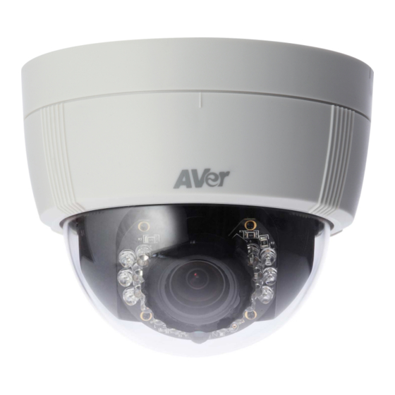
Preface The SF2012H-D is a 2-megapixel dome camera with 3-axis adjustment and a vari-focal lens that allows you to line up the camera precisely where you need it and capture a wide sweep or close into a narrower specific point. It has both the adjustability to capture the exact target area you require and the technology to keep that area under clear day-and-night surveillance. - Page 6 Hardware 1 in/ 1 Relay Out Video Out Audio In Audio Out Power over Ethernet Power Consumption DC 12V 470mA Pan: 172∘ 3-Axis Gimbal Tilt 30∘~90∘ Adjustments Angle Rotation 180∘ Dimensions 132L x 108.4H(mm) Network Ethernet 10/100 Base-T Network Protocol HTTP, TCP/ IP, SMTP, FTP, PPPoE, DHCP, DDNS, NTP, UPnP, 3GPP,RTSP, RTP, RTCP, Multi-casting System...
- Page 7 System Triggered Action Mail, FTP, Save to SD/SDHC card, Relay, NAS Pre/ Post Alarm Yes (Configurable) Security Password Protection Firmware Upgrade HTTP mode, can be upgraded remotely Simultaneous Connection Up to 10 Audio Yes, 2-way(mono) SD/SDHC card management Motion Detection, IP Check, Network Breakdown (wire only), Recording Trigger Schedule, Alarm Video Format...
-
Page 8: Package Contents
Package contents Item Descriptions 1. SF2012H-D 2. Accessory pack 3. Ethernet cable 4. RJ45 socket 5. Power Adaptor(DC 12V /1A) (Optional) 6. CD (User’s Manual and Quick Guide included) -
Page 9: Product Installation
Product Installation Monitor Setting 1. Right-click on the desktop. Select “ Properties” 2. Change “Color quality” to “Highest (32-bit)”. -
Page 10: Hardware Installation And I/O Pin Assignment
Hardware Installation and I/O Pin Assignment 1. Connect a power adapter and IP camera to PC or local network. 3.5mm Phone Jack (Audio Input, Red) 3.5mm Phone Jack (Audio Output, Green) 2. 3-Axis Gimbals Adjustments Pan: 172° Tilt: 30°~90° Rotation: 180 ° Once the users open the case, the gimbals adjustment offers the convenience method to install on the wall. - Page 11 3. I/O Control Instruction I/O terminal connector – used in application, for e.g., motion detection, event triggering, alarm notifications. It provides the interface to: Digital Input (GND+Alarm) : An alarm input for connecting devices that can toggle between an open and closed circuit, for 1.
- Page 12 RELAY INSTALLATION EXAMPLE 2 Trigger the “Normal ON” (Normal Close) indoor illumination off when event / motion occur:...
-
Page 13: Power Over Ethernet (Poe)
Power Over Ethernet (PoE) Set up the IP camera through Power over Ethernet (PoE). PoE is a technology that integrates power into a standard LAN infrastructure. It enables power to be provided to the network device, such as an IP camera, using the same cable as that used for network connection. It eliminates the need for power outlets at the camera locations and enables easier application of uninterruptible power supplies (UPS) to ensure 24 hours a day, 7 days a week operation. -
Page 14: Ip Assignment
IP Assignment There are two ways to find IP Camera: − Finding IP Camera by using “NXU Lite recording software” − Finding IP Camera by using “IP installer” Finding IP Camera by using “NXU Lite recording software” 1. The NXU Lite software is in the attached software CD. Before launching it, please install the software first. - Page 15 3. Click “Setup” button. 4. Click “Add IPCam” button. 5. Select “IP Camera” item.
- Page 16 6. Key in IP Camera’s ID and Password (default is admin/admin) and click “Auto Search” to find camera. 7. In Search Result window, click it the IP camera model that user has purchased (Please ignore ONVIF connection item); the camera is in red text that is configurable. User can double-click on the camera is in red text and configure the IP camera’s setting;...
- Page 17 Finding IP Camera by using “IP installer” Use the software, “IP Installer” to assign the IP address of the IP camera. The software is in the attached software CD. IP installer supports two languages IPInstallerCht.exe: Traditional Chinese version IPInstallerEng.exe: English version There are 3 kinds of IP configuration.
-
Page 18: Using Dhcp Server/Router Network
IP Installer configuration: IP Installer will search all IP cameras connected on the LAN. The user can click “Search Device” to search again. Click one of the IP cameras listed on the left side. The network configuration for this IP camera will show on the right side. -
Page 19: Using Non-Dhcp Server/Router Network
Using NON-DHCP Server/Router Network In Non-DHCP server/router network, the static IP address must be assigned to the device each time when adding another IP camera to the network; the default IP address of the current one must be changed to avoid conflict. Please make sure the Subnet of the PC’s IP address and the IP camera’s IP address are the same. - Page 20 IP camera IP addresses: 1. A quick way to access remote monitoring is to left-click the mouse twice on a selected IP camera in “Device lists” in IP Installer. Upon doing so, the Internet Explorer browser should open.
- Page 21 2. Then, please key in the default “User name” and “Password”, both of which are “admin”.
-
Page 22: Install Activex Control
Install ActiveX Control The first time you attempt to view the camera video via Internet Explorer, it will ask you to install the ActiveX component. If the installation fails, please check the security settings for the Internet Explorer browser. 1. IE Tools Internet Options…... - Page 23 When the following dialogue box appears, click “Yes”.
-
Page 24: Using The Ip Camera Browser Interface
Using the IP Camera Browser Interface The admin have the full access to the IP camera browser interface. The menu on the left, you can expand and navigate to access all the features. Preview Launch the Internet Explorer browser, type the IP address of the IP camera in the address field. It will show the following dialogue box. - Page 25 Name Function (2) Login IP Show PC’s IP address (3) Bandwidth Show current IP camera’s transmitting bandwidth (4) FW Version Show IP camera’s current firmware version (5) Logout Exit the application (6) Zoom control Reset zoom level. Increase zoom level. Decrease zoom level.
-
Page 26: System > General
System > General n this section, only admin level is authorized to configure the IP camera system maintenance and the date and time settings. System > General > Maintenance In the Maintenance tab, the administrator can check the system event log, upgrade the system firmware, reset the configuration settings without having to change the user management and network settings, reboot, and restore all back to factory default settings. -
Page 27: To Upgrade The Ip Camera Firmware
Name Function (4) Firmware Upgrade Upgrade the firmware to the latest version. To Upgrade the IP Camera Firmware 1. Download the file from our website and save it in your computer hard disk. 2. Click Browse. Locate and select the file and click Open. -
Page 28: System > General > Date & Time
System > General > Date & Time In the “Date & Time” tab, the administrator can set and update the system’s date and time. After filling in the correct settings, click Apply to apply the new settings. Name Function (1) Current Date & Time Display the current date and time. -
Page 29: System > User Management
Name Function (4) Setting Method Select the date & time settings method. Sync with current PC – Obtain the date and time setting on the current login computer. Sync with NTP Server – Obtain the date and time setting from NTP server. -
Page 30: System > Network Setting >Setting
password in “Confirm”. Then, click “Add/Set”. User List: Click edit to change the account password. To delete the user account, click Remove button. System > Network Setting > Setting Device Name: Used to name the IP camera to search more easily for this specific one among all connected IP cameras. -
Page 31: System > Network Setting >Sever
System > Network Setting > Sever Used to send out the video via Email or FTP, or to save on NAS. Mail Setting: Used to send out the video via Email. a. Login Method: Click drop-down list to select the method to login Email server – “Account” or “Anonymous”. -
Page 32: System > Network Setting >Ddns
NAS Settings: Used to send out the video to NAS server. a. Enter necessary information in “Location”, “Workgroup”, “Account Name” and “Password” columns. b. If the user wants to create a new folder on the NAS server to save the video file, select “Yes” under the “Create the folder”. - Page 33 Status - Common warning message: Updating! Failed(1), Please check your DNS setting. Failed(2), Please check your internet connection. Failed(3), Please check your internet connection. Failed(6), receiving data failure - Warning message from different service provider: Server Provider : dyndns.org Failed(4),Please check the Dyndns.org. Error : The system parameter given is not valid.
-
Page 34: System > Network Setting >Other 1
System > Network Setting > Other 1 User may need to assign different port to avoid conflict when setting up IP assignment. Click Apply to save the configuration. HTTP Port: setup web page connecting port and video transmitting port (Default: 80) UPnP Support: This IP camera supports UPnP, if this service is enabled on your computer, the camera will automatically be detected and a new icon will be added to “My Network Places.”... - Page 35 Security: Yes is required account and password to connect with this IP camera through ONVIF protocol. No is not required account and password to connect. (Make sure the NVR system supports ONVIF v1.02.) RTSP Keepalive: To keep connection until remote site disconnects it.
-
Page 36: System > Network Setting >Other 2
System > Network Setting > Other 2 Multicast Setting (based on the RTSP Server): User can setup two streaming based on the RTSP Server. Multicast operation example: The application is to get the multicast streaming in the LAN environment. Basically, the users operate VLC player, and then you can get the multicast streaming form IP camera. - Page 37 Step 2: 2. Select Demuxers and RTP/RTSP 3. Select force multicast RTP via TRSP 1. Select all Step 3: Select Media/open network stream...
- Page 38 Step 4: Input rtsp://[IPCAM Address] / [RTSP Path] The URL address should be the same as the RTSP path in Video Stream (System-->Video Stream)
- Page 39 [Notice] a. If the received image is not from the required IP camera, please adjust the value. (Change either IP Address or Port number) b. If the Multicast stream you use doesn’t support RTSP Keepalive, please select NO.
-
Page 40: System > Image
System > Image Admin and operator levels can adjust the Image setting. There are 5 tabs: OSD, Preference, Exposure, Advanced, and Privacy Mask System > Image> OSD In OSD tab, you can enable/disable overlaying time stamp and text title. After completing the setting, click Save to apply the new setting and Cancel to keep the new setting. -
Page 41: System > Image >Preference
System > Image > Preference In Preference tab, you can tune the IP camera white balance, display color or black & white, set the flicker frequency, change the video orientation, and adjust the brightness and contrast. After completing the setting, click Save to apply the new setting and Cancel to keep the new setting. White Balance: Adjust white balance value. -
Page 42: System > Image >Advanced
System > Image > Advanced Click Default button will back to factory default setting. Night Mode: select the setting of night mode. -
Page 43: System > Image >Privacy Mask
System > Image > Privacy Mask For the security purpose, there are three areas can be setup for privacy mask. Click Area #(Area 1, Area 2, Area 3)button first and drag a area on the image screen. Then, click Save button to save the setting. -
Page 44: System > Video Stream >General
System > Video Stream > General Input Resolution: Select the video resolution that is the maximum resolution supported in Stream 1 and Stream 2. Video System: Select the video format. TV Output: Select the video format of TV Output. (depending on different models) -
Page 45: System > Video Stream >Stream 1
System > Video Stream > Stream1 Basic Mode Click Apply to save the configuration. − Resolution: There are 8 resolutions can be chosen -- 1600x 1200, 1280x1024, 1280x960, 1280x720, 800x600, 640x480, 320x240, 176x144. − Quality: There are 5 levels to adjust – Best, High, Standard, Medium, and Low. The higher the quality is, the bigger the file size is. - Page 46 − Video Format: H.264 or JPEG − RTSP Path: It’s a URL address...
-
Page 47: System > Video Stream >Stream 2
System > Video Stream > Stream2 Basic Mode Click Apply to save the configuration. − Resolution: There are 8 resolutions can select -- 1600x 1200, 1280x1024, 1280x960, 1280x720, 800x600, 640x480, 320x240, 176x144. − Quality: There are 5 levels to adjust – Best, High. Standard, Medium, and Low. The higher the quality is, the bigger the file size is. - Page 48 Advanced Mode Click Apply to save the configuration. − Resolution: There are 8 resolutions can select -- 1600x 1200, 1280x1024, 1280x960, 1280x720, 800x600, 640x480, 320x240, 176x144. − Quality: There are 5 levels to adjust – Best, High. Standard, Medium, and Low. The higher the quality is, the bigger the file size is.
-
Page 49: System > Video Stream >Stream 3
System > Video Stream > Stream3 [Note] 3GPP mode suggested setting: 176x144 resolution, 5FPS, MPEG-4 format. Stream 3 Setting: Enable or Disable 3GPP Streaming. 3GPP Path: It’s a URL address. -
Page 50: System > Audio
System > Audio IP camera supports 2-way audio (mono). User can send audio from IP camera built-in MIC (depending on different models) to remote site; User can also send audio from remote site to IP camera’s external speaker. a. IP camera to PC: select “Enable” to start this function. b. -
Page 51: System > Sd Card
System > SD Card Please Insert SD/SDHC card before use it. Make sure pushing SD/SDHC card into the slot completely. [Note]The use of the SD/SDHC card will affect the operation of the IP camera slightly, such as affecting the frame rate of the video. -
Page 52: Event > Arrangement >Motion
Event > Arrangement > Motion Motion Detection: IP camera allows 3 areas motion detection. When motion is triggered, it can send the video to some specific mail addresses, transmit the video to remote ftp server, trigger the relay, and save video to local SD/SDHC card. To set up the motion area 1, click “Area 1” button. Using mouse to drag and draw the area. -
Page 53: Event > Arrangement > Preference
Event > Arrangement > Preference Record File: File Format: IP camera allows 3 different types of recording file to change its record size. When motion/alarm is triggered, there are 3 different types of record mode. − AVI File (With Record File Setting ) −... -
Page 54: Event > Schedule
Event > Schedule Schedule: After complete the schedule setup, the camera data will be recorded according to the schedule setup. Snapshot: After enable the snapshot function; user can select the storage position of snapshot file, the Interval time of snapshot and the reserved File Name of snapshot. -
Page 55: Event > Di/Do
Event > DI/DO IP camera supports 1 input/1 output (depending on different models). When input is triggered, it can send the video to some specific mail addresses, transmit the video to remote ftp server, trigger the relay, and save video to local SD/SDHC card. CAUTION!! Please connect to propriety relay box to reduce the risk of electric shock &... - Page 56 Output Setting: Mode setting: OnOff Switch: Relay status is based on sensor triggered times. Time Switch: To restore the original relay status after the interval time. [Note]GPIO pin define please refer to the part of Front / Back plane & I/O port pin assignment. ALARM INPUT: Normal: 3.3V (The voltage differential from ALM_IN pin &...
-
Page 57: Status Information
Status Information Click Apply button to save the configuration. Networking Info: Displays network information of the IP camera. Product Info: - Server Name: Assigns a name to the IP camera and the name shows on the IP Installer. Also, displays the related information of the IP camera. Mark Status Bar to display the Server Name of IP camera on preview interface. -
Page 58: Network Configuration
Network Configuration Configuration 1 a. Internet Access: ADSL or Cable Modem b. IP address: More than one real IP c. IP camera and PC connect to the internet d. For fixed real IP, set up the IP into IP camera and PC. For dynamic IP, start PPPoE. - Page 59 Configuration 2 a. Internet Access:ADSL or Cable Modem b. IP address:one real IP c. IP camera and PC connect to the internet d. Device needed:IP sharing e. Use virtual IP, set up port forwarding in IP sharing.(Please refer to Network Setting Other 1 UPnP Port Forwarding)
-
Page 60: Factory Default
Factory Default 1. To recover the default IP address and password, please follow the following steps. 2. Remove power, and press and hold the button. Please refer to the picture below. Reset button 3. Power on the camera. Don’t release the button during the system booting. 4. -
Page 61: Troubleshooting
Problem Solution I forgot the account and password for Please refer to the manual of “VI Factory Default SF2012H-D. How can I go back to setting” description. default setting? I can’t find a way to force day mode and We don't provide this function due to the limitation of night mode. -
Page 62: Appendix
Appendix SF2012H-D is compliant with SD/SDHC card and to ensure recording quality, and please use memory cards over 2G and Class 4 above (Max. 32G) MicroSD/SDHC card SD/SDHC Transcend SDHC class4 16GB Transcend SDHC Class 4 16GB Transcend SD class4 16GB... -
Page 63: Fcc Notice (Class B)
© 2012 AVer Information Inc. All rights reserved. All rights of this object belong to AVer Information Inc. Reproduced or transmitted in any form, or by any means without the prior written permission of AVer Information Inc. is prohibited. AVer Information Inc. -
Page 64: Limited Warranty
You as the original purchaser. Except for the foregoing, the Product is provided “AS IS.” In no event does AVer warrant that You will be able to operate the Product without problems or interruptions, or that the Product is suitable for your purposes. Your exclusive remedy and the entire liability of AVer under this paragraph shall be, at AVer’s option, the repair or replacement... -
Page 65: Governing Law And Your Rights
Governing Law and Your Rights This warranty gives you specific legal rights; You may also have other rights granted under state law. These rights vary from state to state.
Need help?
Do you have a question about the SF2012H-D and is the answer not in the manual?
Questions and answers